S S P
C
A
Ing
ettore Con ettore SciAd
resentataCoordinat
Alberto La
D
egneria
ncorsuale entifico dvanced
Asse
da: Ditore Dott
amberti
OTTOR
a Civile
e di afferen isciplinared Minor
essmen
iego Maratorato
EsamRATO DI
e, Ambie
Ciclo XX
nza: 08/B3 e: ICAR/09TITOLO
r Destru
nt of Ex
astoni me finale aRICER
entale e
XVIII
3 9TESI
uctive T
xisting M
anno 2016RCA IN
e dei M
Testing
Masonr
Relator
Andrea
Correla
Luca Pe
6Material
for the
ry
re
a Benede
atore
elà
i
etti
ACKNOWLEDGMENTS ... I
ABSTRACT ... III
SOMMARIO ... V
CHAPTER 1. INTRODUCTION ... 1
1.1. AIMS AND OBJECTIVES OF THE THESIS ... 3
1.2. OUTLINE OF THE THESIS ... 5
CHAPTER 2. STATE‐OF‐THE‐ART OF EXPERIMENTAL AND NUMERICAL ANALYSIS OF MASONRY ... 7
2.1. STATE‐OF‐THE‐ART OF THE EXPERIMENTAL CHARACTERISATION OF MASONRY ... 7
2.1.1. Destructive Testing (DT) ... 11
2.1.2. Minor‐Destructive Testing (MDT) ... 14
2.1.3. Non‐Destructive Testing (NDT) ... 25
2.2. STATE‐OF‐THE‐ART OF THE NUMERICAL ANALYSIS OF MASONRY ... 31
2.2.1. FE modelling for masonry assessment ... 33
2.2.2. Constitutive models for masonry assessment ... 37
CHAPTER 3. A NOVEL PENETROMETER FOR IN‐SITU MINOR DESTRUCTIVE TESTING ... 41
3.1. GEOMETRY OF THE NEW PENETROMETER ... 42
3.2. THEORETICAL INTERPRETATIVE MODEL ... 44
3.3. EXPERIMENTAL CAMPAIGN ... 48
3.3.1. Materials ... 49
3.3.2. Preparation of specimens... 49
3.3.3. Test execution ... 50
3.4. EXPERIMENTAL CALIBRATION OF THE INSTRUMENT ... 52
CHAPTER 4. INTEGRATED LABORATORY METHODOLOGY FOR MINOR DESTRUCTIVE TESTING ... 55
4.1. EXPERIMENTAL CAMPAIGN ... 58
4.1.1. Materials ... 59
4.1.2. Standard Mechanical Characterisation of Materials ... 60
4.1.3. Extraction of Specimens ... 66
4.2. EXPERIMENTAL TESTING OF THE SPECIMENS EXTRACTED ... 68
4.2.1. Brazilian Tests on Cores with Inclined Diametral Mortar Joint ... 69
4.2.2. Double Punch Tests on Mortar Joints ... 73
4.3. INTERPRETATION OF THE EXPERIMENTAL RESULTS ... 75
4.3.1. Brazilian Tests on Cores with Inclined Diametral Mortar Joint ... 75
4.3.3. Double Punch Test ... 85
4.3.4. Standard Tests ... 87
4.4. INTEGRATED METHODOLOGY OF MICRO‐MECHANICAL INTERPRETATION ... 89
4.4.1. Theoretical Development for Continuum Model ... 90
4.4.2. Theoretical Development for Interface Model ... 97
4.4.3. Experimental Data Processing Software ... 101
CHAPTER 5. NUMERICAL VALIDATION OF LABORATORY EXPERIMENTAL TESTS ... 105
5.1. LINEAR ANALYSES OF BRAZILIAN TESTS ... 106
5.2. ISOTROPIC DAMAGE MODEL FOR NONLINEAR ANALYSES ... 110
5.2.1. Constitutive Model and Failure Criterion ... 110
5.2.2. Characteristic Length for the Discrete Models ... 113
5.3. 3D NONLINEAR ANALYSES OF BRAZILIAN TESTS AND TRIPLETS ... 114
5.4. 2D PLAIN STRAIN NONLINEAR ANALYSES OF BRAZILIAN TESTS AND TRIPLETS ... 117
5.5. DISCUSSION AND COMPARISON OF THE NUMERICAL RESULTS ... 120
5.5.1. Brazilian Test on Cores with Inclined Diametral Mortar Joint ... 120 5.5.2. Triplet Shear Tests ... 128 CHAPTER 6. CONCLUSIONS ... 135 6.1. SUMMARY ... 135 6.2. MAIN CONTRIBUTIONS ... 138 6.2.1. Penetrometer for in‐situ MDT ... 138 6.2.2. Laboratory Tests for MDT ... 139 6.2.3. Numerical modelling of laboratory tests ... 142 6.3. SUGGESTIONS FOR FUTURE WORK ... 143 REFERENCES ... 147 FIGURE CAPTIONS ... 159 TABLE CAPTIONS ... 165
Acknowledgments
The research reported in this Doctoral Thesis was carried out in the Department of Civil, Environmental and Material Engineering (DICAM) of the University of Bologna, with the support of the Department of Civil and Environmental Engineering (DECA) of the Technical University of Catalonia during the Internship period of the Ph.D. Candidate.
The work reported in this thesis has been possible thanks to the financial support by the University of Bologna and the “Marco Polo” mobility programme, which are gratefully acknowledged.
Part of this study has been developed within the MICROPAR research project (ref. BIA2012-32234) funded by the MINECO (Ministerio de Economia y Competitividad of the Spanish Government) and the ERDF (European Regional Development Fund), whose assistance is gratefully acknowledged.
The work has been carried out under the guidance of Prof. Andrea Benedetti and Prof. Luca Pelà.
I am very grateful to Prof. Andrea Benedetti for his continuous help and support, his wise advices and the way he faced my research with excitement and motivation. Thanks also for proposing me for the Doctor Europaeus status.
A special thank goes Prof. Luca Pelà for the given opportunity to collaborate with a prestigious institution as the UPC-BarcelonaTech. His precious presence has been crucial for my professional and personal growth during the Ph.D. programme.
I wish also to thank to Prof. Pere Roca for his important advices during my internship period in Barcelona.
ii Acknowledgments
I would like to acknowledge the whole staff of the LISG Laboratory of the University of Bologna (UNIBO) and also the LATEM Laboratory of Technology of Structures and Materials of the Technical University of Catalonia (UPC-BarcelonaTech) for the support during the experimental campaigns carried out during this research.
Thanks also to the International Center for Numerical Methods in Engineering (CIMNE) for providing GiD and COMET software packages, without which part of this work could not have been possible.
I am thankful to all my friends and colleagues of the University of Bologna for the moments we shared together.
Very special thanks goes to my friends met in Barcelona, to whom I send my best wishes and I hope to see them soon.
I also want to thank my friends of my hometown, they have been always present in my life although far from me.
I am very grateful to my family for their support in every moment, without which I could not reach this important goal.
Finally, my gratitude goes to my girlfriend Elisa, her patience and support during the last five years have been an inspiration for me. Thank you.
Abstract
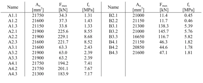
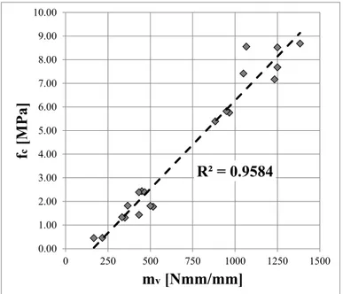
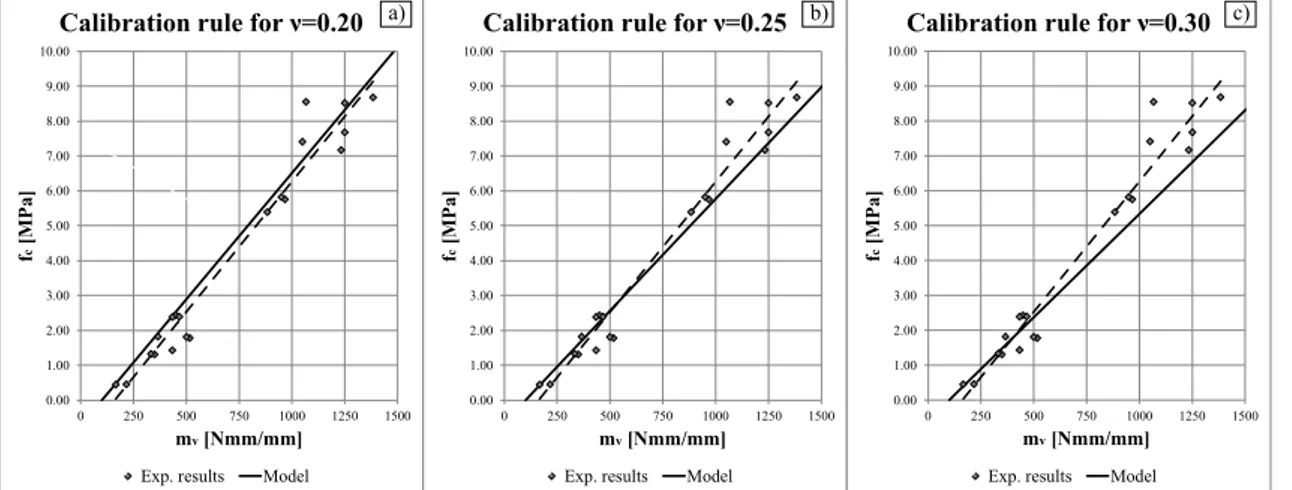
The mechanical characterisation of material components in existing masonry structures has been the topic of several research studies. Most of them are currently focusing on mortar, the most difficult material component to be characterised, trying to evaluate its behaviour. To achieve this aim, a good option is performing minor-destructive testing (MDT) such as the in-situ penetrometric tests or the extraction of samples to be tested in the laboratory. This thesis focuses on MDT for the mechanical characterisation of historical mortars. In the first part, a novel in-situ MDT technique is investigated, based on the field vane shear test for soils. The instrumentation consists in a four-winged pin (X-Drill) and a torque wrench. The testing procedure consists in inserting the pin in a mortar joint and applying a torque to the pin through the dynamometric key. The dynamometric key records the magnitude of the torque while the pin brings the material to failure. This research presents the results of an experimental campaign based on the comparison between standard tests and X-Drill measurements on different types of mortars. The interpretation of the test, based on the analysis of the local stress evaluated on the failure surface, provides a possible correlation between the measured torque and the compressive strength of the material.
After the X-Drill development, the thesis focuses on the extraction of samples to be tested in laboratory. The in-situ core drilling of existing masonry is a convenient sampling technique since it does not induce excessive damage to the historical structure and it allows a direct estimation of the mechanical properties by testing the extracted specimens in the laboratory. Brazilian tests can be carried out on cores including a diametral mortar joint with a defined inclination with respect to its original horizontal
iv Abstract
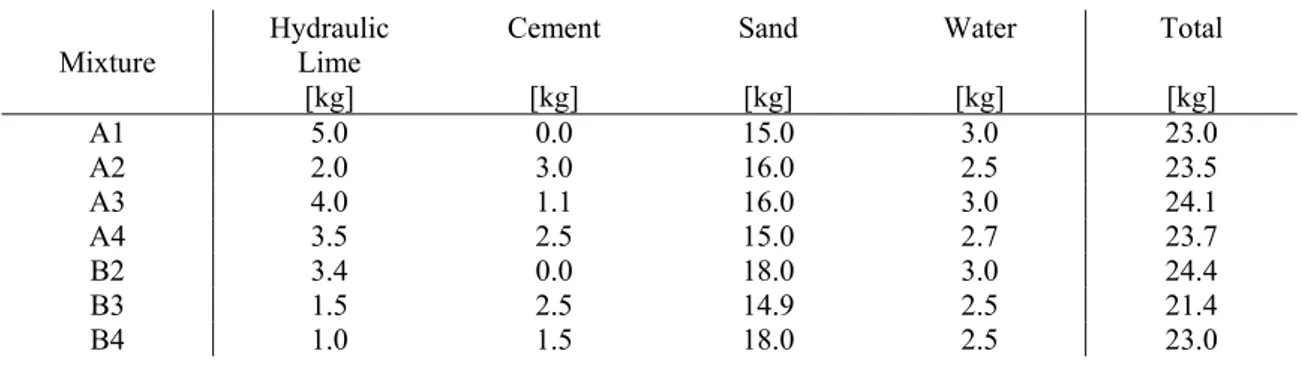
position. A new integrated methodology is developed for the comprehensive mechanical characterisation of historical mortar based on different types of experimental tests results. This task is carried out by means of a large set of experiments performed ex-novo on lime mortar masonry walls built in the laboratory. The processing of the results from Brazilian tests on cores with inclined diametral joint is complemented with the application of the double punch tests on mortar joints that may be also extracted through core drilling. The proposed experimental methodology is then compared with the results obtained from standard tests performed on the same materials, such as compression tests, flexural tests and shear tests on triplets.
Finally, the parameters obtained are used as input parameters for 2D and 3D numerical analyses based on the Continuum Damage Mechanics constitutive model. This model allows to represent the material mechanical degradation through a single scalar parameter, which depends on the fracture energy dissipated during the failure process. The comparison between the experimental results and the numerical analyses confirm the good prediction capacity of the proposed techniques.
Keywords: Minor-Destructive Tests, Penetrometric Tests, Historical Masonry Assessment, Lime Mortar, In-Situ Sampling, Double Punch Test, Mohr-Coulomb Theory, Shear Strength, Failure Envelope, Nonlinear Analyses, Fracture Mechanics, Continuum Damage Model.
Sommario
La caratterizzazione meccanica dei materiali che compongono strutture in muratura è stato l’oggetto di numerosi studi di ricerca. La maggior parte di questi è incentrata sulle malte, essendo il materiale più difficile da caratterizzare, cercando di stimarne il comportamento meccanico. Per raggiungere questo obiettivo, una buona opzione pare essere quella di utilizzare test moderatamente distruttivi (MDT), come prove penetrometriche o estrazione di campioni da testare in laboratorio.
Questo lavoro è focalizzato sulle tecniche MDT per la caratterizzazione meccanica di murature storiche. Nella prima parte viene studiata una nuova tecnica MDT in-situ basata sul Field Vane Test per i terreni. La strumentazione, infatti, consiste in un chiodo alettato (chiamato X-Drill) e una chiave torsiometrica. La procedura di test consiste nell’inserire il chiodo in un letto di malta e successivamente nell’applicare un momento torcente mediante una chiave dinamometrica. Quest’ultima registra il valore massimo di torsione mentre il chiodo porta a rottura il materiale. Si presentano i risultati di una campagna sperimentale basata sul confronto di test di compressione standard con le letture di prove X-Drill eseguite su campioni di malta di proprietà differenti. La calibrazione è stata basata sull’analisi delle tensioni locali sulla superficie di rottura, ottenendo una possibile correlazione tra momento massimo misurato e resistenza a compressione del materiale.
Successivamente, la ricerca si è concentrata sull’estrazione di piccoli campioni da testare in laboratorio. Il carotaggio di campioni in situ eseguito su murature esistenti può essere una tecnica conveniente, dal momento che non produce lesioni eccessive sulla struttura e permette una stima diretta delle proprietà meccaniche. La prova
vi Abstract
Brasiliana può essere eseguita su carote che includano un giunto di malta diametrale, ponendo quest’ultimo inclinato rispetto alla direzione orizzontale. Viene proposta una tecnica integrata di caratterizzazione meccanica per le malte storiche che si basa sull’analisi e confronto di diversi tipi di prove sperimentali. Questa metodologia è stata sviluppata con l’ausilio di una campagna prove eseguita ex-novo in laboratorio su elementi in muratura con malta di calce idraulica. L’utilizzo combinato della prova Brasiliana su carote con giunto di malta inclinato e delle prove a punzonamento su lastrine di giunto di malta estratte dal muro ha consentito di stimare un dominio di rottura come inviluppo degli stati tensionali corrispondenti a ciascuna prova. I risultati sono poi stati confrontati con quelli ottenuti da prove standard di compressione, flessione e taglio su triplette.
Infine, i parametri ottenuti dall’elaborazione sono stati utilizzati per la realizzazione di analisi numeriche su modelli agli elementi finiti 2D e 3D con leggi costitutive basate sulla meccanica del danno continuo. Tali leggi permettono di rappresentare il degrado del materiale attraverso un unico parametro scalare, il quale dipende dall’energia dissipata durante la frattura. Il confronto tra risultati sperimentali e numerici ha confermato la bontà del modello proposto per la caratterizzazione delle malte storiche.
Parole chiave: Prove Limitatamente Distruttive, Prove Penetrometriche, Vulnerabilità Murature Storiche, Malta di Calce, Campionamento In-Situ, Double Punch Test, Teoria Mohr-Coulomb, Resistenza Taglio, Inviluppo Rottura, Analisi Non-Lineari, Meccanica della Frattura, Modello Danno Continuo.
Chapter 1. Introduction
The assessment of historical buildings has become a fundamental topic in the conservation of the architectural heritage, especially in the last decades where relevant catastrophic events have threatened many important structures. The evaluation of the structural health and the identification of possible vulnerabilities in those facilities shall allow the preservation of the cultural heritage value that they represent.
The conservation of the architectural heritage requires a multidisciplinary approach involving a variety of professionals and organisations. For this reason, in 2003 the International Council on Monuments and Sites produced a document of recommendations (ISCARSAH 2003a; ISCARSAH 2003b) to assist the professional figures involved in historical masonry assessment and facilitate the communications between them.
The current approach for the historical building assessment can be defined “Knowledge-Based Assessment” and requires information about the original structural conception, its construction techniques, the possible damages or modifications occurred in the building life and finally on the present state. As reported in the aforementioned document (ISCARSAH 2003a), the diagnoses are based on historical qualitative and quantitative approaches; the qualitative approach is mainly based on direct observation of the structural damage and material degradation as well as historical and archaeological research. On the contrary, the quantitative approach is mainly based on material and structural tests, monitoring and structural analyses. Concerning the latter one, data and information should first be processed approximately, to establish a more comprehensive plan of activities in proportion to the real problems of the structures. In some cases, it is
2 Chapter 1
convenient to organise the material characterisation in stages, beginning with simple techniques and eventually integrating them with more sophisticated methodologies. Non-destructive tests should be preferred to those that may involve any alteration to the structure. However, those kinds of tests often do not provide the required reliability concerning the investigated material’s results. In this case, it should be necessary to assess the benefit to be obtained by opening up the structure in terms of reduced structural intervention against the loss of culturally significant material (a cost-benefit analysis). For this reason, minor-destructive tests are increasingly used for the assessment of existing structures, providing more reliable results than non-destructive tests while maintaining a limited damage on the investigated part.
Masonry is one of the most common materials in European heritage buildings. The building technique of masonry structures is mostly the same since centuries ago, consisting in superposing blocks or raw stones and, eventually, filling the joints by using mortar. The heterogeneous nature of the material introduce even more uncertainty on its mechanical behaviour, since the structural element capacity depends on the complex interaction of the units and mortar joints. Masonry structures are generally composed of materials characterised by very low tensile strength and that may easily show cracking or separation between elements. Nevertheless, these signs are not necessarily an indication of danger as masonry structures are intended to work mainly in compression.
The preliminary analysis of masonry requires the identification of the characteristics of the constituent materials: the units (stones or bricks) and the type of mortar (cement, lime, etc.). It is also necessary to know how the elements are bonded (dry joints, mortar joints etc.) and the way in which they are geometrically related to each other. Different kinds of tests may be used to ascertain the composition of the wall.
Focusing on the Italian territory, where the earlier European societies have settled and developed important technologies for the building construction, masonry structures have to deal with the seismic hazard. The latest important seismic events occurred in the Italian territory, such as Umbria-Marche in 1997, L’Aquila 2009 and Emilia-Romagna 2012, caused huge damages on lots of historical masonry buildings. Italian governance faced with these casualties introducing the approach proposed by ICOMOS in the current Standard (D.M. 14/01/2008 2008).
F ( Fi ev no di th lo Fi N be ab sa as Th ch st Figure 1.1 Eff a), Prefecture igure 1.1a,b vidences of oticeable in isruption of he wall bear ocal mechan igure 1.1b) Nowadays, a ehaviour by bout the cr afeguarding ssessment o 1.1. Ai he main ai haracterisati ages: - developm - compariso testing of mortar jo fect of earthqu e Palace in L'A b,c show s f the real n these pict f the mortar ring capacit nisms of fai or separatio a significant y means of racking or the cultura f buildings. ims and O im of this ion of histo ment of a nov on between f extracted oint and D uake on mason Aquila, Italy in ome collap losses in tures, one o r, leading to ty. Furtherm ilure, such a on among st t effort is ca mechanical failure phe al heritage a . Objectives thesis is to orical maso vel MDT fo n some nove material (i Double Pun nry structures n 2009 (b) and pses occurr case of h of the prin o disconnec more, maso as those inv tructural par arried out to l tests perfo enomena in and allows of the The o provide a onry. The w or the in-situ el non-stand i.e. Brazilia nch Test of : Basilica of S d Clock Towe ed during high magnit cipal cause ction of the onry structu volving vau rts (Figure o understan ormed in-sit n the eleme developing esis a reliable m work was d u mechanic dard MDT t an Test on f mortar jo Saint Francis in r in Finale Em the aforem tude earthq es of collap units and ures are ofte ults and roo
1.1c). d better the tu. A more ent investig g more relia methodology developed fo al character techniques b cored sam oints) and in Assisi, Italy milia, Italy in 2 mentioned ev quakes. As pse is the c consequen en characte ofs (Figure e existing m precise kn gated could able models gy for expe following tw risation of m based on la mples with available y in 1997 2012 (c). vents as s clearly complete nt loss of erised by 1.1a and materials’ nowledge help in s for the erimental wo main mortar; boratory inclined standard
4 Chapter 1
approaches (i.e. compression, flexural test of mortar prisms and shear tests of masonry triplets).
According to the ICOMOS Guidelines (ISCARSAH 2003b), it is preferable to plan the characterisation of materials of existing masonry structures in stages, processing firstly the outcomes of simple tests that could provide a first impression on the structural health. Secondly, the information retrieved from the first stage can help to choose further and more comprehensive experimental methodologies, such as those including MDT.
According to the aforementioned Guidelines, the first part of the present research provides a new technology for quick in-situ evaluation of the mechanical properties of historical mortar. The proposed technique, called X-Drill penetrometer, reveals to be a promising methodology of investigation, since the instrumentation is quite cheap and the test is simple as for the execution and the interpretation of the results.
The second stage of the research investigates non-standard techniques as an alternative to standard tests that usually cannot be performed on historical masonry. The direct comparison between standard and non-standard techniques is carried out considering historical-like materials reproduced in the laboratory according to the traditional construction practice.
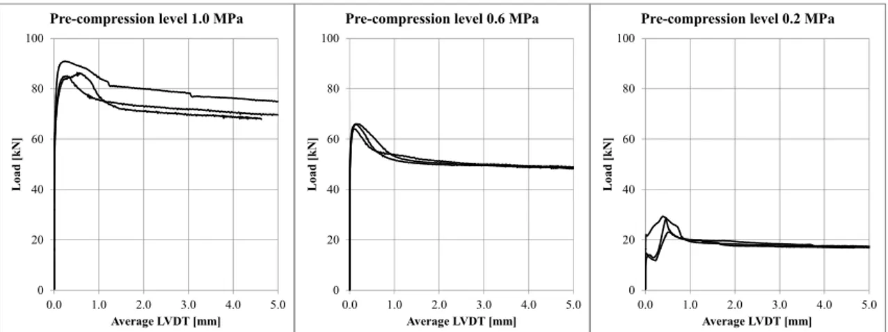
The experimental setup for Brazilian Test on core samples with inclined mortar joint is enhanced compared to previous works available in the literature. The introduction of linear variable differential transformers (LVDTs) placed parallel to the joints allows to measure the relative displacement of the two halves of the specimens and thus to derive important mechanical parameters. Moreover, the combination of different non-standard tests provides a new integrated methodology for a better interpretation and a more robust prediction of the materials’ mechanical parameters.
The outcomes of the interpretation can be used as input parameters for numerical analyses, based on advanced constitutive models, such as Continuum Damage Mechanics ones, that can give further information on the nonlinear behaviour of the resisting element.
1.2. Outline of the Thesis
This thesis consists in six Chapters.
Chapter 1 provides the introduction and the objectives of the research.
Chapter 2 presents a brief overview on the current masonry standards in the European Union both for new masonry constructions and for the historical masonry assessment. A state-of-the-art of available experimental and numerical techniques currently used for existing masonry assessment is also included.
Chapter 3 presents the development of a novel MDT instrumentation. The X-Drill is based on the field vane test used for soils, consisting in a four-winged pin inserted in the material. A torque is then applied to the pin through a dynamometric key, which records the maximum value at failure. The calibration of the instrument was carried out in laboratory using a large set of mortar specimens with different compressive strengths. The analysis of local stresses on the material led to a linear correlation between the maximum torque measured and the compressive strength of the mortar. The proposed interpretation method returned a high prediction capacity on the mortar strength.
Chapter 4 presents a large experimental campaign carried out on specimens extracted from masonry walls reproduced in the laboratory using historical-like materials. The experimental campaign included also standard specimens prepared following the current standards for compression, flexural and shear tests. The extraction was carried out using a novel dry coring technique instead of water-cooled coring, in order to collect less disturbed specimens. Once the core samples were extracted, the walls were dismantled to obtain mortar joint specimens to be tested through DPT. These two tests can be performed in real experimental campaigns on existing structures, while the standard tests are hardly applicable since the samples extracted are not prismatic and regular. The core samples were subject to Brazilian Test with inclined mortar joint (BT), which induces a composite state of stress on the mortar joint. The test was enhanced by introducing LVDTs on both circular faces in order to measure the relative displacement of the bricks shaping the joint. This solution provided information about elastic, strength and nonlinear properties of mortar. The outcomes of BT and DPT were combined using a 3D representation of the state of stress (i.e. Mohr’s Circles), allowing defining a more precise estimation of failure envelope. The resulting compressive, tensile and shear strengths obtained by the failure envelope were compared with the standard tests performed, confirming the good agreement of the results.
6 Chapter 1
Chapter 5 validates the experimental results presented in the previous Chapter 4 by means of 2D and 3D FE analyses based on a Continuum Damage Mechanics constitutive model. In particular, the samples tested were modelled using micro-models (i.e. units and mortar were defined separately as a heterogeneous model) with the parameters obtained by the integrated interpretation.
Chapter 6 presents an extended summary, the main contributions of this work and the conclusions that can be derived from this study. Suggestions for future work are also pointed out.
Chapter 2. State-of-the-art of experimental and
numerical analysis of masonry
This Chapter presents a critical review of the state-of-the-art on experimental and numerical approaches for the analysis of existing masonry.
The available experimental approaches can be classified into Destructive Tests (DT), Minor Destructive Tests (MDT) and Non-Destructive Tests (NDT), depending on the procedures adopted during the testing operations.
The available numerical approaches can be classified depending on the type of analysis performed (i.e. linear/nonlinear and static/dynamic), on the modelling scale (i.e. macro, micro or multi-scale) and on the constitutive law assumed (i.e. elasticity, plasticity or damage mechanics).
2.1. State-of-the-art of the experimental characterisation of masonry
The current European Standard for new masonry construction is the Eurocode 6 (EN 1996-1-1:2005 2005). The first part of the standard reports the minimum requests in terms of material quality, such as composition, durability and mechanical properties. Concerning mortar, the material used must agree with the EN 2:2010 (EN 998-2:2010 2010) which contains all the information about the preparation procedures, the proportions of sand, binder and water and the durability requirements. The binder used in the mortar can be either cement (EN 197-1:2011 2011) or hydraulic lime (EN 459-1:2010 2010). EN 1015-1:1999 (EN 1015-1:1999 2007) reports the necessary analyses
8 to be pe dimensi void con Regardi a list of such as (EN 10 specime Figu The uni dependi units co (EN 77 1:2011 where t their tes Once t expressi starting reported compres erformed on ions of the ntents is rep ing the mec
f standards three-poin 015-11:2007 ens and the
ure 2.1 Instruc its used in m ing on their omposition 1-1:2011 20 (EN 772-1: their classifi sting proced the mechan ions in ord from thos d in Equatio ssive streng n the granul grain sizes. ported in the chanical pro for the me t bending a 7 2007), w loading inc
ctions for mor
masonry co r nature. Th and their s 011), while 2011 2011) fication is su dures in EN nical prope der to evalu se of the c on 2.1a,b fo gth and it ometry of s Other info e following operties, the echanical c and compre which defin rement ratio rtar: testing se onstruction he most used standardised e their mech ). The same ummarised 772-6:2011 erties are uate the ho components or the estima ts Young’s m sand by mea ormation ab g parts of EN EN 998-2: characterisat ession tests nes the cu o necessary
etup (a) and m
are classifi d units are d dimension hanical char subdivision in EN 771 1 (EN 772-6 identified, omogenised s. Some ex ation of the modulus . ans of sieve out durabili N 1015. 2010 (EN 9 tion of mor are describ ring time, y to perform moulding (b) (E ed accordin clay bricks ns are desc racterisation n is made fo -6:2011 (EN 6:2011 201 Eurocode mechanica xamples of e characteris es, granting ity, water ab 998-2:2010 rtars. The o bed in EN 1 the dimen m a correct te EN 1015-11:2 ng to differe and natural ribed in EN n is reporte or the natura N 771-6:20 1). 6 provid al properties empirical stic value of Chapte a well grad absorption a 2010) repo ordinary te 1015-11:19 nsions of t est. 2007 2007). ent standard al stones. Cl N 771-1:20 ed in EN 77 al stone uni 011 2011) a des empiric s of mason relations a f the mason er 2 ded and rts sts 99 the ds, lay 11 72-its, and cal nry are nry
∙ . ∙ . ; 1000 ∙ (2.1a,b)
Where is a constant dependent on the masonry units used, and are respectively compressive strength of units and mortar.
The shear behaviour of masonry can be estimated through specific tests described in EN 1052-3:2002 (EN 1052-3:2002 2002), which provides the procedures to be followed in order to obtain the initial shear strength. Such parameter allows to define the failure envelope in terms of stresses (i.e. Mohr-Coulomb), considering the possible crack formation as a two-dimensional interface failure.
In the specific case of the evaluation of existing masonry, the experimental procedures contained in the aforementioned standards appear inappropriate, since the constituent materials usually do not comply with the minimum requirements of composition or material strength. Moreover, the dimensions of the specimens required by the standards are hardly obtainable from an existing structural element. For this reason, it is necessary to define novel reliable methodologies for the accurate mechanical characterisation of masonry components in existing structures.
The Italian Cultural Heritage is composed mainly of historical masonry buildings, largely diversified in materials and construction techniques. Due to the high seismic hazard of the Italian territory, the national governance had to introduce further instructions and rules for the prevention and the restoration of the historical building. These rules were collected firstly in the Italian Standard (D.M. 14/01/2008 2008) in 2008, and then extended to its Instructions (Circolare 02/02/2009 n. 617 2009).
Italian Standards provide a precise schedule to be followed in order to obtain the requested level of knowledge of the investigated building, based on the European Recommendations for the safeguard of the Cultural Heritage buildings (ISCARSAH 2003a; ISCARSAH 2003b). Firstly, it is necessary to retrieve the documentation about the structure realisation, such as original design projects, historical information about restoration interventions, structural alterations or relevant damages. All these information can contribute to the identification of the structural system and to the estimation of the loads acting on the resisting structure. Secondly, it is necessary to plan a survey to find possible incongruences between the original project and the current condition of the building. Once the global resisting system is identified, it is finally necessary to proceed with the material characterisation by performing experimental tests.
10 Chapter 2
The Instructions of Italian Standard (Circolare 02/02/2009 n. 617 2009) provide a table containing reference values of mechanical parameters for different types of masonry. The proposed reference values refer to masonry realised with weak mortar, thick joints and no transversal interconnection between eventual multiple layers. If the masonry investigated presents some kind of reinforcement or is in better condition than in the reference condition, it is possible to use some correction factors to increase the mechanical properties. For limited and adequate levels of knowledge (named as LC1 and LC2), the parameters assumed for the vulnerability analysis of the structure must comply with the range provided by the former table. Possible higher results obtained by experimental tests can be used only to increase the parameters that in any case have to fall within the range provided. If the number of tests performed is sufficiently large (exhaustive tests), it is possible to assume an accurate level of knowledge (i.e. LC3) allowing using directly the results of the experimental tests. The aforementioned standard reports the type of tests to be performed in order to consider the requested knowledge level. For example, if the level of knowledge LC3 is needed, Destructive Tests (DT) or Minor-Destructive Tests (MDT) are required. Non-Destructive Tests (NDT) are allowed as complementary tests, reducing the amount of DTs or MDTs. In fact, the Instructions to the Italian Standard (Circolare 02/02/2009 n. 617 2009) suggest that MDTs and DTs can be replaced for a total amount of 50% with NDTs by tripling the number of the tests removed.
Recent studies (Borri et al. 2011; Galli et al. 2014) showed that the Instruction to the Italian Standard provides conservative values, suggesting that operating in an accurate level of knowledge could lead to more reliable results and could significantly reduce the restoration interventions.
In addition to the National Standard, Italian Regions can provide further regulations to describe more in detail the assessment of historical masonry. As an example, the Tuscan “Regional Program VSM” (VSM Regione Toscana 2003) provides a complete characterisation of the masonry typologies that can be encountered on the territory, organised as an abacus with a standardised classification (see Figure 2.2).
D th co its in da co A 20 Th hy pe Figure 2.2 E 2.1.1. De T consists m hem to failu omplete cha s ultimate c nvestigated s amaged par omplete dem An useful D 003), in whi he outer p ydraulic jac erformed fo Example of th estructive T mainly of te ure in order aracterisatio capacity. Ho structural el rt. In comm molition or p DT is the di ich a mason art of the cks, which or compress he abacus for t Testing (DT) esting eithe to define th on of the m owever, suc lements to f mon practice partial demo iagonal com nry structura investigate h provide a sive strength the masonry te Toscana 20 T) er mid or lar their mecha material, sinc ch technique failure and e, this appr olition and mpression t al member d portion i a controlled h (if the co extures by the 003). rge-size stru anical behav ce the inves es are highl require a co roach is fea subsequent test (Brigno is isolated f is demolish d compress ompression e Tuscany Reg uctural elem viour. These stigated elem y invasive s onsequentia asible in str reconstruct ola et al. 2 from the sur hed to allo sion. The is given pe gion (VSM Re ments until e methods l ement is tes since they b al substitutio ructures des tion of som 2008; Corra rrounding s ow the inse test can b erpendicular egione bringing lead to a ted until bring the on of the stined to me parts. adi et al. tructure. ertion of be either r respect
12 to the j compres Figure (Corrad load, thu Milosev reprodu masonry joints) or f ssion is giv Figure 2 2.3 shows di et al. 200 us the angle vic et al. 2 ucing the te y due to the
for the eva en in diagon 2.3 Diagonal c the exper 3). It requir e of applica 2012) exten est in the la e different p aluation of nal direction compression te imental set res an almo ation of the nded the i aboratory. T position of th composite n). est performed tup of the ost square-sh load is fixe investigation The studies he mortar c compressi d in-situ (Corra in-situ dia haped part ed at 45°. O n to all th s showed th ourses (see on-shear ac adi et al. 2003 agonal com of the pane Other studies he possible he biaxial Figure 2.4) Chapte ctions (if t 3). mpression te el subjected s (Page 198 e inclination anisotropy ). er 2 the est to 81; ns, of
F A ge us 2. ot Th in co te m Figure 2.4 Biax A comprehen eneral strate sed were pr 5) compose ther by diffe he single m nformation omposition. echniques fo massive wall xial behaviou nsive resear egy for the repared in ed mainly b erent kind o Figure 2.5 O materials w concerning The tests for in-plane l specimens r of mortar su rch project material c laboratory by natural st of binders (e Overview of m were charact g compress on the st or out-of-and in-plan ubjected to dia 1981) (NIKER Pr characterisat following t tones, fired earth, lime, materials used terised usin sive and t tructural m -plane loadi ne cyclic sh agonal compre ) roject 2010 tion of exis the commo -clay bricks gypsum or in NIKER (N ng the avai ensile stren members we ing scenari hear tests (se
ession at differ 0b) was carr sting mason n masonry s or mudbri cement mor NIKER Project ilable stand ngth, Youn ere perform os, perform ee Figure 2. erent inclinatio ried out to nry. The sp typologies icks connec rtars). t 2011) dard tests to ng’s modu med using d ming static 6a). ons (Page define a pecimens s (Figure cted each o obtain ulus and different tests on
14 Figure 2. As an characte hysteret indicate cracking Despite expensi applicat stability needed 2.1.2 Differen occurren structur immedi instrum represen appear r Commo test to d .6 Cyclic test o example, th eristic softe tic loops sh e the degra g. the high re ve since it tions (see F y of the glob to avoid co 2. Minor-D nt techniqu nces. MDT ral element ate structu mentation an ntativeness rather scatte only used M determine th on stone maso he cyclic t ening behav hown in Fig adation of t eliability of requires la Figure 2.3). bal structur mpromising Destructive ues were d T is based o . It produc ural replace nd time, but of the test ered, being MDTs to be he stress lev onry panel: sp Proj ests perform viour of ma gure 2.6b an the mechan the results arge and co In addition re might be g the vertica Testing (M developed i on mechani ces limited ement. Thi t it introdu t. In fact, b historical m performed vel on a vert pecimen after oject 2011). med on ma asonry elem nd the reduc nical proper obtained by omplex inst n, by isolat compromi al load-bear MDT) in order to ical tests pe d damage t is solution uces more u by reducin masonry a he d on masonr tical panel (
failure (a) and
assive wall ments. In fa cing slopes rties at eac y DT, the ex trumentation ting the ele sed, thus a ring system o reduce c erformed on that usually n reduces uncertainties ng the inves eterogeneou ry structure (ASTM C11 d hysteretic lo l specimens act, the env of the unlo h cycle du xperimental ns especiall ement to in support fra . osts, risks n a small p y does not the costs s derived fr stigated are us material. s are the si 196 1991) a Chapte oops (b) (NIKE s showed t velope of t oading curv ue to mater l setup is ve lly for on-s nvestigate, t ame is usua and dama portion of t t require a in terms from the loc ea the resu
ingle flat ja and the doub
er 2 ER the the ves rial ery ite the lly age the any of cal ults ack ble
fla (A le in ja ci is m in sin di F C ja di re in po m str th at jack to e ASTM C119 east three co n case of the ack. Then, e ircular saw, necessary material. Thi nformation o ngle flat ja istance betw igure 2.7 Flat oncerning t acks is brou ifferent stag edistribute t nternal part ositioned ei must be repe ress-deform he composit estimate the 97 1991). T ouples of m e single fla either a sin allowing th to measure s technique on the elast ack test, th ween the ma t Jack Test: cu the double ught to failu ges, increas the stresses at the jack ither vertica eated at eac mation curve e material a e Young’s The test pro marker-point at jack, or in ngle mortar he jacks to b e the dislo e is an appli tic propertie he oil is pu arker-points ut and insertion flat jack te ure (Figure sing the pre
on the mat s is carried ally or hori ch loading e, necessary and its Poiss
modulus a ocedure star ts placed eit nside the in r joint or tw be inserted cation of t cation of th es of the ma umped into s is recovere n of the jack ( Test (c
est, the oil i 2.7c). The essure of th terial. The d out by me zontally res step. The i y to have a son’s ratio.
and the com rts by measu ther over an nvestigated wo joints h (Figure 2.7 he marker-he stress rele aterial by re the jack a ed (Figure 2
(a), Single Fla c) is pumped u e loading du he oil at eac measureme eans of gaug spect to the information an estimatio mpressive st uring the di nd below th area in case have to be
a). Just afte points due easing meth emoving a p and gradual 2.7b). at Jack Test (b until the m uring the te ch step and ent of local ges. These e mortar joi n obtained a on of the Y trength of m distances bet he investiga e of the do cut by mea er the cut is to the rem hod, which p part of it. In ally until th b) and Double material betw est is carrie d then hold deformatio instrument ints. The pr allows defi Young’s mo masonry tween at ated area uble flat ans of a made, it moval of provides n case of he initial Flat Jack ween the ed out in ding it to on in the s can be rocedure ning the dulus of
16 These te provide jack tes Cathedr showing loading-each cy Figure A comp properti hole-dri procedu quantifi propose the prin deforma very com Instead 2008), f (Figure stresses some c
ests are wid useful info st (see Figu ral of Noto g good res
-unloading cle and the
e 2.8 Double F late
plementary ies was pre illing test ure consist ication of th ed method a ncipal stre ations (ε1, ε mplex and c of using th for the analy
2.9a) in o from the d constants th dely used in ormation ab ure 2.8a) fo (Binda et sults in the cycles sho softening b
Flat Jack Test eral and vertic
method to esented by L for isotrop ts in adap he residual s allows the d esses (σmax 2 and ε3) reg consists of hree strain g ysis of maso order to re deformation hat correlat n mechanica bout the ma or the mech al. 2003; B e evaluation owed the ch behaviour of : prospect of t cal strains vs. v o the singl Lombillo (L pic linear-e pting a n stresses for deduction, b and σmin) gistered in t several step gauges as p onry it is pr duce possib ns registered e the defor al characteri aterial inves hanical cha Binda et al. n of the de haracteristic f the materi the masonry in vertical stress le flat jack Lombillo et elastic mat normalized a heterogen by means of , and thei three direct ps that have proposed in referable to ble experim d in the stra rmations c isation of ex stigated. Bi aracterisatio . 1999; Bin eformability c decay of al (Figure 2 nvestigated (a s (b) (Binda et k for the e t al. 2010) terials (AS experimen neous mater f a suitable m ir direction tions. The e e all a strong the relative use a large mental bias ain gauges i aught in th xisting maso nda used th n of the re nda & Tirab
y of the m the elastic 2.8b). a) and plot of t t al. 2003). valuation o as an appli STM E837 ntal proced rial such as m mathematic n (β), basi xperimenta g influence e standard ( number of s. The dedu is strongly i he strain g Chapte onry and th he double f emains of t boschi 199 materials. T properties
the results for
of the elas ication of t 2008). T dure for t masonry. T cal process, ing on thr al procedure in the resul (ASTM E8 f strain gaug uction of t influenced gauges. The er 2 hey flat the 9), The at r tic the The the The of ree e is lts. 37 ges the by ese
co pa of (F Fi A sa m ad re of re pr str ho ty co onstants ca arameters, s f a test base Figure 2.9b) igure 2.9 Hole An interestin amples to b must inflict dopted is ve epresentativ f a wall is d emoved from roperties of ructures. T orizontal an ypes of spe ontaining on an be obta such as You ed on the rea ). e-drilling tech for the cal
ng alternativ be subject to the lowest ery importan e of the in-difficult, sin m the orig f the comp he common nd perpendi ecimens ca ne diametra ained in a ung’s modu alisation of hnique: detail o libration of th ve techniqu o destructiv t possible nt, since the -situ materi nce the mat
inal locatio posite mate n sampling icular to the an be extra l mortar joi theoretica ulus and Po f a wall of si of the gauge p he analytic met ue for mino ve testing in damage to e specimen al. The extr terial is bri on. The sam
erial, is al g technique e face of a acted from int or multip al way dep isson’s ratio imilar quali positioning (a) thod (b) (Lom or-destructiv n the labora the histor s must be a raction of m ttle and usu mpling of w lmost impo is by mea structural m m the existi ple joints (F pending on o, or experi ity to the ma
) and test exec mbillo et al. 20 ve testing i atory. The s rical structu as undamage mortar samp ually crumb wall portion ossible for ans of core member, lik ing wall, s Figure 2.10) n few dim imentally b material teste cution in the l 010). is the extra sampling pr ure. The te ed as possib ples from th bles as soon ons, to eval existing h drilling pe ke a wall. D such as sp ). mensional y means ed in situ laboratory action of rocedure echnique ble to be he joints n as it is luate the historical erformed Different pecimens
18 Figure 2. Benedet deriving cores ex variable 2012; B combina from 45 since m maintain et al. 1 since th undistur In other cylindri its origi induces tangenti can be a 10 Cylindrica
tti and co-w g the streng xtracted from e inclination Benedetti & ations of sh 5º to 60º. T much more
ning the sam 996; Bened he mortar jo rbed mortar r recent stu ical samples inal horizon to the mort ial shear (F applied to th al specimens e workers (B gth envelop m an existin ns of the di & Pelà 20 hear-compre This method e informati me inclinati detti et al. oint keeps c r specimens udies (Pelà s were teste ntal positio tar in the jo Figure 2.11b he mortar jo extracted by co joint s Benedetti et e of histori ng building iametral mo 012). The ession stress d takes the on can be ion of the m 2008). Bes confined by . et al. 2012 ed with the n in the wa oint a stress b). Differen oint by vary ore-drilling: s specimens (b) al. 2008) ical mortars . Different B ortar joint r mortar joi ses by varyi e most adva e obtained mortar joint sides that, t y two brick 2; Maraston diametral m all (Figure state of sim nt combinat ying the diam
single and thre
focused on s by testing
Brazilian te respect to th
int could b ing the joint antage from than in B t, e.g. 45º (B the samplin ks, allowing ni et al. 201 mortar joint 2.11a). Suc multaneous tions of she metral joint ee joint specim n single-join 70 to 110 ests were ca he horizonta be subject t inclination m this kind Brazilian te Braga et al. ng techniqu g the extrac 16; Pelà et t inclined w ch special t normal com ear-compre inclination Chapte
mens (a) and tw
nt specimen mm mason arried out w al (Pelà et to differe n, for instan of specime ests execut 1992; Filar ue is effecti ction of rath al. 2015) t with respect testing set-mpression a ssion stress n. er 2 wo ns, nry ith al. ent nce en, ted rdi ive her the to up and ses
F Th in 19 jo ob (tr A jo an ch an (c Fi sy w ce M th ra str ob sp Figure 2.11 Br
his last imp nformation
996), where oint of 45º. btaining a r riplets) and All the afore oint showed nd strength haracterised nd involvin combined so igure 2.12a ymmetric” ( with low-stre ement morta MPa. A recen he aforemen anges of str rength histo bserved. Ot plitting of t razilian Test o provement from the te e the Brazil In these st relationship big (walls) ementioned d that the mo h of morta d in most ca ng the uppe ometimes w a. This m (Pelà et al. 2 ength morta ar character nt study car ntioned one rength value orical morta ther author the core or on cored samp its interpret of the exp ests than in ian tests we tudies from p between th assemblage studies abo ode of failu ar. In case ases by a fr er and lowe with detachm mode of fa 2015) and i ars perform rised by a c rried out by using lime es are actua ars. For hig rs (Mazzott r pure shea
ple with diame tation (b) (Ben perimental t n previous ere carried m the ninetie the shear st es of cemen out Brazilia ure of the sp e of low-racture cros er brick-mo ment of a s ailure was it was obser med firstly b compressive Pelà (Pelà mortar with ally represe gher strengt ti et al. 20 ar sliding a
etral joint rota nedetti et al. 2
technique l studies (Br out with a es, the auth trength of th nt mortar m an tests on pecimen is s strength li ssing the m ortar interfa small brick called “p rved in expe by Braga ( e strength ra et al. 2015) h compressi entative of th mortars, 14) report along the b ated respect to 2008). led to the d raga et al. fixed inclin hors were m he joint and asonry. cores with strongly dep me mortar mortar joint a aces at the wedge clo parasymmet erimental pr Braga et al ange betwee showed the ive strength the behavio different ty failures res brick-morta o the horizonta derivation 1992; Filar nation of th mostly inter nd those of h inclined d pendent on r, the failu at the core’ sample ext se to the lo tric” or “c rograms car l. 1992) wi en 1.8 MPa e same outc h of 1.9 MP our of typi ypes of failu sulting from ar interface al (a) and of more rdi et al. e mortar rested in medium diametral the type ure was ’s centre tremities oad), see centrally rried out ith lime-a lime-and 2.5 comes of Pa. These cal low-ure were m either (Figure
20 2.12b), conside observe splitting cement Figur “parasy sliding Another by the U Compre on the l test is p surfaces loading with a cem red represe ed in previo g the brick mortar. ure 2.12 Mode ymmetric” or g along the bri
r interesting UIC 778-3 r ession tests ateral surfa performed in s are regula plates as sh ent-lime mo entative of ous study s parallel t s of failure ob “central symm ick-mortar int 2014; Bra g testing tec recommend are perform ce. The cyli n the same arised by m hown in Fig ortar with h a low-stre (Braga et a to the load bserved in Bra metric” fractu terface (Mazzo aga et al. 1992 chnique on m dations of th med on mas inder is cen direction in means of m gure 2.13. higher streng ength histo al. 1992), direction azilian tests on ure (Pelà et al. otti et al. 2014 2) for higher s masonry cy he Internatio sonry cylin ntred in the m n which the mortar caps gth of 7.8 M orical morta showing an (Figure 2.1 n cores with in 2015) for low 4) and c) split strength morta ylindrical sp onal Union nders with 1 middle of a e load is exp between th MPa, that co ar. Similar n almost v 2c), for a nclined diame w-strength mo ting failure (M ars. pecimens is of Railways 150 mm dia vertical joi pected to ac he sample Chapte ould be hard results we vertical crac high-streng etral joint: a) ortars; b) shear Mazzotti et al. that propos s (UIC 199 ameter load int, so that t ct. The later
and the ste
er 2 dly ere ck, gth r sed 5). ded the ral eel
Th te m cl Th th re A H sp of in te Pe sl Figure 2. he UIC 778 ested for eac method was lay brick ma he sampling he structure epresent the A research a Henzel and pecimens ex f existing m nvestigated. echnique to elà et al. 20 enderness r 13 Setup of th 8-3 recomm ch type of used by Br asonry (Bre g technique is affected interaction about the m Karl (Henz xtracted from mortar stre Due to the evaluate th 012; Sassoni ratio of the s he compressio mendations brickwork, rencich and encich et al is consider by the extra among uni mechanical c zel & Karl
m an existin ength, since particular s he influence i et al. 2014 specimens o on of three join suggest tha but six sho d co-worker . 2004; Bre red as minor action, whi its, horizont characterisa 1987) on ng wall. Th e it provid shape of th e of the thi 4). These st on the maxi nt cored speci at a minimu ould prefer s to evaluat encich & St r destructiv le the speci tal and verti ation of exis the Double his work is des reliable e specimen ickness of t tudies show imum load ( men (Brencic um of three ably be use te the comp erpi 2006; B e, since only men is suff ical mortar j sting mortar e Punch Te widely used informatio s, several st the specime wed a strong (see Figure ch & Sabia 20 samples sh ed if availa pression str Bilello et a ly a small po ficiently com joints. ar was publi est on mor d for the ev on on the tudies enric ens (Drdáck g dependenc 2.14a). 08). hould be ble. The rength of l. 2007). ortion of mplex to ished by rtar joint valuation material ched this ký 2011; cy on the
22 Figure 2 Other s surfaces to ensur al. 2014 with no regulari stronger assessin the DPT Another techniqu tests mu eventua standard strength the Win codes a standard The latt former surface, inversel 2.14 Influence capp studies inve s on the res re the plana 4) compared on-capped ised cut spe r than the ng that capp T, but using r type of in ue, since th ust be perfo al plaster or d tests for o h by perform ndsor Probe assess (AST d explosive ter approac is more app , a metal p ly proportio e of the slende ping for irregu
estigated on ults obtaine arity of the d the outcom specimens. ecimens wit extracted ping on non g properly ar n-situ tests e entity of d ormed direct r coating s other mater ming micro e, initially TM C803 20 e cartridge o ch is more propriate fo pin is force onal to the c rness of the sp ular specimen n the influe ed from the loading are mes of DPT In additio th non-stan samples (F -regular spe rrangements classified b damage cau tly on the m surfaces. Th rials (mainly o-destructive designed fo 010). The in or a spring appropriat or cement b d to penetr compressive pecimens on t ns of mortar (V ence of po DPT. The ea by mean Ts performe on, Válek ndard ones Figure 2.14 ecimens has s can reduc between ND used at the s material to i hese tests a y concrete) e analysis. for hardened nstrumentat g-based syst te for testin based ones. rate in the e strength of the maximum Válek & Veiga
ossible irreg solution pro s of caps. S ed using dif (Válek & capped wit 4b). Both r s a strong in e the scatter DT and MD structure is m investigate, are usually useful to e The most c d concrete tion consist tem with a ng low stre After shoo material. T f the concre load (Drdáck a 2005) (b). gularities of ovided by t Some autho fferent capp Veiga 200 h mortar de reported sim nfluence on ring around DT is the p minimal. Ho requiring th an adjuste estimate the common pe investigatio s in a gun l defined en ength morta oting at the The penetra ete (Figure 2 Chapte ký 2011) (a) an f the loadi these works ors (Sassoni ping materia 05) compar esigned to milar resul n the results d the results penetrometr owever, the he removal ed version e compressi enetrometer on as the U loaded with nergy amou ars, since t investigati ation depth 2.15a). er 2 nd ng s is et als red be lts, of . ric ese of of ive r is US h a nt. the ion is
G ex dr fix O (L th of de str pr st Gucci’s pene xisting mor riller connec xed depth (F Figure 2.15 ther resear Liberatore e he dynamic f blows nee ensity of the rength. In rovided by a andard scle etrometer ( rtar (Gucci cted to an e Figure 2.15 5 Penetrometr rchers dev et al. 2001) penetromet eded by the e material a order to ha an internal s erometer (Fi PNT-G) is & Barsotti electronic ap b). ric techniques veloped di or Felicetti tric test for e probe to and, by usin ave a const spring-base igure 2.16b) a different i 1997). Th pparatus th : Windsor Pro fferent typ i (Felicetti & soils (SPT penetrate f ng a proper tant impact ed impact m ). t system fo he instrume at measure
obe (a) and Gu
pes of pe & Gattesco , Standard P for a stand empirical f energy on mechanism ( or the in si ent is comp the energy ucci's Penetrom enetrometers 2006), taki Penetration ard depth i formulation each blow Figure 2.16 itu investig posed of a necessary t meter (PNT-G s, like Li ing inspirati n Test). The is correlate n, to its com w, the percu 6a) or by me gation of portable to drill a G) (b) iberatore ion from number d to the mpressive ussion is eans of a
24 Fig Sclerom of a ma rebound possible the rebo of plaste Using sclerom rebound gure 2.16 Pen metric test is ass hitting t d height of e to estimat ound effect er or coatin a similar metric pendu d of the mas netrometric tec Penetr s also well-the materia the mass, w te the comp on the mate ng, principle, ulum, and t ss (Figure 2 chniques: Libe rometers (Feli -known as N al surface (E which is dire ressive stre erial to inve Van Der he rebound .17). eratore’s (Lib icetti & Gatte
NDT for co EN 12504-ectly correl ength. Since estigate, usu Klugt (Va d index is e eratore et al. 2 sco 2006) (b) oncrete, bas 1:2009 200 lated to its s e the operat ually it is n an Der Klu expressed as 2001) (a) and ed on the re 09). After m superficial h ing principl ecessary to ugt 1991) s the maxim Chapte Felicetti's rebound effe measuring t hardness, it le is based remove pa developed mum angle er 2 ect the t is on arts a of
W m th an Th th co So be th an Figure 2.1.3. No
With the intro masonry stru he structure nd electrom he sonic me hrough a m ommonly us - Sonic tran - Sonic/seis - Sonic/seis - Sonic reso onic transm etween 500 he wave is i n accelerom e 2.17 Pendulu on-Destruct oduction of uctures, sev without da magnetic wav ethod refers medium at sed sonic m nsmission m smic tomog smic reflect onance met mission meth Hz and 10 initiated by meter which um scleromet tive Testing f new techno eral NDT t amaging it. ves in the m s to the tran sonic frequ methods are: method. graphy. tion method thod. hod involve 0 kHz throu the impact can be pos ter developed g (NDT) ologies in th techniques w Most of the material. nsmission a uencies (M d. es the passin ugh the elem
of the forc sitioned dir by Van Der K he structura were develo em are base and reflectio McCann & ng of a com ment under e hammer, rectly oppos Klugt (Van De al health mo oped to obt ed on the pr on of mech Forde 200 pressional w investigatio and recepti site the emi
er Klugt 1991) onitoring of tain inform ropagation hanical stres 01). The fiv wave at freq on. Transmi ion is perfo itter (Figure ) f existing mation on of sonic ss waves ve most quencies ission of rmed by e 2.21a).
26 In some Thus a can be p and rec wave ve establish Figure 2 Sonic to (Saisi et surfaces section, receiver three-di section correlat the stru tomogra e cases, it i semi-direct performed. ommendati elocity is an h the positio 2.18 Transmiss omography t al. 2000). s. A dense n where eac r through th imensional (see Figur ted with zon ucture. It is aphic metho Figure 2. is not possi t (Figure 2.2 The results ions (ACI C n average o on and the e sion modes fo y represents Tests are pe net of ray-p ch one refer he structure reconstruct re 2.19) so nes of weak usual to ass od. 19 Example o ible to place 21b) or indi s are adjuste Committee f the local v extent of an or sonic wave For an improv erformed al paths thus c rs to a spec e. These va tion of the v that local kness or dif sume a line of tomography e the receiv irect (Figure ed through 228 2004; velocity alo ny possible m tests: direct (a rde 2001). vement in t long paths t crosses the w cific travel alues of trav velocity dis variations fferent mat ear structura y compared to ver directly e 2.21c) con empirical ru Yaman et ong the path material dis
a), semi-direct
the sonic tr hat are not wall of the time betwe vel time ca stribution a in velocity erial layers al response
the wall textu
y opposite to nfiguration ules provid al. 2001). h and it is n scontinuity. t (b), indirect ransmission perpendicul structure or een the soni an be used cross the se y can be i in the inte in the appl ure (Colla 200 Chapte o the emitt of the prob ded by autho The resulti not possible (c) (McCann n test meth lar to the w r the mason ic source a to compute elected cros identified a ernal fabric lication of t 09). er 2 ter. bes ors ing to & hod wall nry and e a ss-and of the
In the sonic reflection method both the emitter and receiver of the sonic wave are placed on the same face of the masonry (as for indirect transmission shown in Figure 2.18c), but the stress wave recorded is the direct stress wave reflected from any discontinuity interface of the element investigated. The velocity calculated from the rear wall or face of a structure is a measure of the local velocities along the path.
The problems that can be investigated by reflection methods are: - Internal dimensions and shape of the masonry element. - Type and properties of fill.
- Voiding within the fill material.
- Cracks and voids within the internal fabric of the structure.
Seismic waves, which are also generated by an impact source, are commonly referred to NDT applications and propagate at frequencies in the range from 100 Hz to 1 kHz. The range of frequencies refers both to seismic and sonic waves, thus in practice the terms are often interchanged. Despite its advantages, the sonic reflection method is not recommended since the resolution achievable with the low frequency energy is poor and it is often difficult to distinguish reflections from surface waves and refracted arrivals (McCann & Forde 2001).
The most recent development of sonic and ultrasonic methods is known as the “Impact– Echo” test method (McCann & Forde 2001; Colla 2003), which was originally developed to measure concrete thickness and integrity from one surface. The method is performed on a point-by-point basis by using a small-instrumented impulse hammer to hit the surface of the material investigated at a given location. An accelerometer mounted adjacent to the impact location records the reflected energy, as reported in Figure 2.20.
28 Since re energy r analysis (FRF) i transfer wave en which c and “pri detect v this case a hidde rapid to frequen It is wo high att incident eflected sign recorded in s using a fas s then calcu r function o nergy. Thes can be eithe imitive” ap voids presen e, the wall w n cavity or o use since ncy. orth mentio tenuation ch t and reflec Figure 2.20 “ nals are mo n the time do st Fourier tr ulated for th or frequenc se peaks allo er the outer plication of nce behind was tapped r defect pro the human ning that u haracteristic cted waves “Impact-Echo ore easily id omain is pa ransform (F he impulse cy spectrum ow identify r surface of f the “Impa plaster due with a ligh oduced a sig n ear is extr ultrasonic m cs and nume s. The ultra o” principles s dentified in assed to a si FFT). A tran generated a m record in
ying the pos f the materi act-Echo” m e to its eve htweight ham gnificant ch remely sens methods are erous bound asonic meth cheme (Colla the frequen ignal analys nsfer or freq and resonan dicate refle sition of the ial or intern method was entual detac mmer and th hange in fr sitive to the not feasibl daries result hods, gener 2003) ncy domain ser for frequ quency resp nt frequency ections or e discontinu nal defects.
used for sev hment from he sound as equency. T e change in le in mason ting in scatt rated by a Chapte n, the receiv uency doma ponse functi y peaks in t echoes of t uity interfac A simplifi everal years m the wall. ssociated w The method n the resona nry due to ttering of bo piezoelectr er 2 ved ain ion the the es, ied to In ith is ant its oth ric
tra m So de 2. Fi Im (M al el en Th F ansducer at metal casting ome attemp efects of sin 21b) (Gabr igure 2.21 Ult mpulse rada McCann et llowing to in lement to i ncountered he principle Figure 2.22 Ra t frequencie gs or for non pts were m ngle compo rielli & Coll
rasonic tests p ar uses the al. 1988) ncrease the investigate. by the wav e of radar te adar principles es above 2 n-destructiv made for id onents such la 2014). performed on same instru but usually resolution On each v ve, part of i echnique is r s (McCann & 0 kHz, are ve testing of dentifying m h as units (
brick unit (a)
umentation y deploys h reducing th variation o it is reflecte reported gra Forde 2001) et al. 2011 more suita f concrete. material pro (Figure 2.21 and mortar sp as for Gro higher frequ he penetratin of mechanic ed and capt aphically in
(a) and its app ) (b). able for de operties an 1a) or mort pecimen (b) (G ound Penetr uency anten ng capacity cal properti tured from n Figure 2.22 plication on m etection of nd locating tar samples Gabrielli & Co rating Rada nna above y to the dept ies of the the receive 2a. masonry eleme flaws in specific s (Figure olla 2014) ar (GPR) 1 GHz, th of the material er probe. ent (Colla
30 Infrared visible structur opening even wi material presenc Moreov infiltrati reports the roof rapid as In gene retrievin paramet recomm 02/02/2 tests to experim d thermogra spectrum b res characte gs) or dama ith presence ls or cavitie e of cracks Figure 2 ver, moistur ion of wate dark areas f. This meth ssessment o eral, NDT ng general ters for the mendations f 009 n. 617 major des mental camp aphy is bas by means of rised by vo ages emit di e of plaster. es producin connecting 2.23 Thermog re concentr er that can related to h hod has pro f large build techniques informatio mechanical for historica 2009; ISC structive on paign of mec sed on the f specific in oids (such as iffering amo This pheno ng a differen the opening raphy overvie ation can b n provide fu higher mois oved to be m dings. s are more on on the l characteris al structure CARSAH 20 nes, providi chanical tes conversion nfrared sen s chimney o ounts of inf omenon is d nt radiation gs at the fir ew of a buildin be easily id further dam sture conten most effect e suitable f e structure sation. For t assessment 003b) sugge ing useful i sts on the bu n of the th nsors. It was or niches), fra-red radia due to differ n. In Figure rst floor. ng façade (Co dentified, al mages on th nt of the wa ive as a rec for a quali health an this reason t t (D.M. 14/ est to use N information uilding obje ermal radia s observed discontinuit ation (Colla rent thermal 2.23 it is n olla et al. 2008 llowing find e structure. all due to ra connaissanc itative surv nd providin the current /01/2008 20 NDTs as co n to plan an ect of invest Chapte ation into t that mason ties (enclos a et al. 200 l inertia of t noticeable t 8). ding eventu . Figure 2. ainwater fro ce tool for t vey, allowi ng only fe standards a 008; Circola omplementa an appropria tigation. er 2 the nry sed 8), the the ual 23 om the ing ew and are ary ate
2.2. State-of-the-art of the numerical analysis of masonry
Once the mechanical characterisation of the material is achieved, it is necessary to analyse the structural system through numerical models. The masonry assessment can be based on linear and nonlinear analyses both in static and dynamic configurations on finite element models or using local analyses with kinematic approach.
Linear static analysis is the most simple analysis to be performed. The Italian Standard (D.M. 14/01/2008 2008) suggests it only for simple structures. Linear dynamic analysis (i.e. Modal Analysis combined with response spectrum analysis) is widely used in seismic assessment, since it provides further information on the dynamic behaviour of the structure such as influence of modal components on the global behaviour (see Figure 2.24a). The hypothesis of linear materials is however the major limitation to the reliability of these analysis.
Nonlinear static analyses (Pushover) are well-known in the professional practice, and consist in step-by-step analyses increasing the horizontal loading until the collapse. The constitutive model of the elements is nonlinear. The equilibrium can be calculated on the deformed geometry at each step, thus including also the nonlinear geometric effects. The results give information about the ultimate capacity of the structure, considering the nonlinear behaviour in the resisting elements (see Figure 2.24b and Figure 2.24c). Nonlinear dynamic analysis (Time-History) considers all the nonlinear properties of the materials subjected to a time-dependent action that usually is defined by accelerograms. This analysis is the most expensive in terms of computational costs, since it is based on the integration of motion equations for each degree of freedom. For this reason, Time-History analyses are limited to special case-studies (Figure 2.24) and are not so widely used in practice-oriented works.
32 Figure 2. nonlinear Local an produce mechan element of analy large po Figure 2 24 Vibrationa r model of San nalyses are es the sep nisms. Thes t as a rigid b yses is used ortion of wa 2.25 Local fail al mode for S. n Marco churc (c) usually per paration fro se analyses body whose d for safegu alls under th lure of masonr wall unde Marcello Pist ch in L’Aquila and Time-His rformed on om the str are based e failure is arding the e hrusting roo ry based on lim er thrusting roo toiese Bridge a (Italy) (Endo story analysis structural p tructure lea on limit-a determined eventual ov fs (Figure 2 imit analysis: of (b) (NIKER in Lizzano (It o et al. 2015) results (d). parts, in wh ading to t analysis pri d by a lack o verturning o 2.25b), etc. overturning o R Project 2010 taly) (Pelà et a (b): Pushover
hich the crac the formati nciples, co of equilibriu f facades (F f facade (a) an 0a). Chapte al. 2009) (a) a r capacity curv acking proce ion of loc onsidering t um. This ty Figure 2.25 nd of portion er 2 and ves ess cal the ype a), of
Se m re M re m 2. ev (s F 2.2.1. FE Figure 2.26 modell everal mod masonry stru esulting in d Masonry tex epresenting mortar-units 26b) and le ventual crac see Figure 2 Figure 2.27 M E modelling 6 Modelling st ling; (c) simpl delling appr uctures (Roc different lev xture (Figur all the ma interfaces. eads to a de ck or slips 2.27a,b,c). Micro-modellin deforme g for mason trategies for m lified micro-m roaches are ca et al. 20 vels of comp re 2.26a) ca aterials as a This approa finitely prec between un ng of masonry ed mesh at pea nry assessm masonry struct modelling; (d) e currently 10). The di plexity and an be repre a continuou ach is comm cise descrip nits and joi
y shear walls (L ak load (b); de
ment
tures: (a) mas macro-model available ifferent app cost. esented with us mesh com monly know ption of the nts by mea Lourenço 199 eformed mesh onry sample; lling (Lourenç to deal wi proaches use h its hetero mprehensiv wn as micro material, al ans of disco 96): load displ h at collapse (c (b) detailed m ço et al. 1995)
ith the ana e different ogeneous n ve of discon o-modelling llowing con ontinuous in lacement diag c). micro-). alysis of theories, ature by ntinuous g (Figure nsidering nterfaces rams (a);