A
A
l
l
m
m
a
a
M
M
a
a
t
t
e
e
r
r
S
S
t
t
u
u
d
d
i
i
o
o
r
r
u
u
m
m
–
–
U
U
n
n
i
i
v
v
e
e
r
r
s
s
i
i
t
t
à
à
d
d
i
i
B
B
o
o
l
l
o
o
g
g
n
n
a
a
DOTTORATO DI RICERCA IN SCIENZE CHIMICHE
Ciclo XXVII°
Settore Concorsuale di afferenza: 03/B1- Fondamenti delle Scienze Chimiche e Sistemi Inorganici
Settore Scientifico disciplinare: CHIM/03- Chimica Generale ed Inorganica
SYNTHESIS AND CHARACTERIZATION OF FUNCTIONAL INORGANIC
NANO-MICRO PARTICLES AND THEIR ROLE IN INNOVATIVE
PRACTICAL APPLICATIONS
Presentata da:
Dott. Eros D’Amen
Coordinatore Dottorato
Relatore
Prof. Aldo Roda
Prof.ssa Simona Fermani
ABSTRACT
In this thesis, the synthesis of nano-micro particles of crystalline inorganic materials and four different applications involving their use, are presented . Inorganic particles have been
synthesized following two main criteria: i) the particle’s dimensions, specific surface area and crystalline phase of the product have been optimized for the practical application; ii) both the synthesis and application should be based on a simple procedure, environmental low impact, economical affordability.
In particular, Titanium dioxide nanoparticles have been synthesized by sol-gel hydrolysis of Titanium(IV) isopropoxide in an isopropyl alcohol/water solution. The isopropyl alcohol contained in the solvent mixture act as a capping agent stabilizing the forming nanometric particles, and play also a role in the suspension stability. Synthesized Titanium dioxide reveals good photocatalytic properties directly as synthesized, without needing further thermal
treatment. Photoactive Titanium dioxide have been used for NOx pollutants abatement on waste gases produced by a working plant and as self-cleaning coating on photovoltaic Silicon panels, showing good results.
Crystalline calcium phosphate nano and micro particles, in particular Hydroxyapatite, Brushite, Monetite and Mg-doped β-Tricalcium phosphate have been synthesized. Two applications of the synthesized Calcium phosphates are reported, both based on the drug delivery concept.
Hydroxyapatite nanocrystals were used to adsorbe and retain on their surface anticancer drugs based on a Platinum complex, and release them in response to a pH variation.
Phytotherapics active elements have been stabilized by physisorption on Calcium phosphates particles surface. The administration of the obtained suspensions shows good results in terms of plant’s healing, using a lower amount of phytotherapic elements compared to the commercial products.
RIASSUNTO
In questa tesi sono riportate sintesi e caratterizzazione di nano-micro particelle di materiale cristallino inorganico, e quattro loro applicazioni. Le particelle inorganiche sono state preparate seguendo due criteri principali: i) le proprietà chimico-fisiche delle particelle devono essere ottimizzate in funzione dell’applicazione; ii) sintesi e applicazione devono essere basate su procedure semplici, con basso impatto ambientale ed economicamente sostenibili. In
particolare, nano particelle di Titanio biossido sono state sintetizzate tramite reazione di idrolisi di Titanio(IV) isopropossido in una soluzione di acqua a alcol isopropilico. L’alcol isopropilico presente nella miscela di solventi agisce da agente cappante stabilizzando le nanoparticelle in formazione e dimostra un ruolo nella stabilità della sospensione. Il Titanio biossido prodotto ha rivelato buone proprietà foto catalitiche senza bisogno di ulteriori trattamenti termici. Il Titanio biossido foto attivo è stato applicato con buoni risultati nell’abbattimento di NOx dalle
emissioni di uno stabilimento e come strato autopulente su dei pannelli fotovoltaici. Sono state sintetizzate nano e micro particelle di calcio fosfati cristallini, nello specifico Idrossiapatite, Brushite, Monetite and β-Tricalcio fosfato Mg-sostituito. Ne sono riportate due applicazioni, entrambe basate sul concetto di drug delivery. Nanocristalli di Idrossiapatite sono stati utilizzati per adsorbire e ritenere sulla loro superficie farmaci chemioterapici basati su complessi di Platino, e successivamente rilasciare il farmaco in risposta ad una variazione di pH. Alcuni principi attivi fitoterapici sono stai stabilizzati tramite fisisorbimento sulla superficie di particelle di Calcio fosfati in sospensione. La loro applicazione ha dimostrato buoni risultati curativi sulle piante, utilizzando quantitativi di principio attivo molto ridotti rispetto ai prodotti commerciali.
INDEX Pag.
1-INTRODUCTION 1
1.1- NANOMATERIALS 1
1.1.1- HETEROGENEOUS CATALYSIS USING NANOMATERIALS 5
1.2- SEMICONDUCTOR MATERIALS 7
1.3- TITANIUM DIOXIDE 9
1.3.1- POLYMORPHS DESCRIPTION 10
1.3.2- PHOTOCATALYSIS MECHANISM IN SEMICONDUCTOR MATERIALS 13
1.4- CALCIUM PHOSPHATES 16
1.4.1- CALCIUM PHOSPHATES IN BIOMEDICAL APPLICATIONS 18
1.5- AIM OF THE THESIS 20
2- EXPERIMENTAL SECTION
2.1- PHOTOACTIVE TITANIUM DIOXIDE 222.1.1- TITANIUM DIOXIDE SOL-GEL SYNTHESIS (Synthesis 1) 22
2.1.1.1- TITANIUM DIOXIDE THERMAL TREATMENT 23
2.1.1.2- TITANIUM DIOXIDE HETEROCOAGULATION ON SILICA (Synthesis 2) 23
2.1.1.3- PHOTOACTIVITY TEST: METHYLENE BLUE SOLUTION (Experiment 1) 24
2.1.2- NOx PHOTOCATALYZED ABATEMENT 25
2.1.2.1- NOx PHOTOCATALYZED ABATEMENT, STATIC CONDITIONS (Experiment 2) 25
2.1.2.1.1- SILANE/SILICA SUPPORT COATING (Synthesis 3) 28
2.1.2.2- NOx PHOTOCATALYZED ABATEMENT, FLUXING
CONDITIONS (Experiment 3) 29
2.1.2.3- NOx PHOTOCATALYZED ABATEMENT, FLUXING CONDITIONS (Experiment 4) 31
2.1.2.4- NOx PHOTOCATALYZED ABATEMENT, FLUXING CONDITIONS (Experiment 5) 33
2.1.3- PHOTOVOLTAIC PANELS COATING (Experiment 6) 35
2.2- CALCIUM PHOSPHATES NANO-MICRO PARTICLES 36
2.2.1- SYNTHESIS OF CALCIUM PHOSPHATES 36
2.2.1.1- HYDROXYAPATITE SYNTHESIS (Synthesis 4) 36
2.2.1.2- BRUSHITE SYNTHESIS (Synthesis 5) 37
2.2.1.3- BRUSHITE SYNTHESIS (Synthesis 6) 38
2.2.1.4- BRUSHITE SYNTHESIS (Synthesis 7) 39
2.2.1.5- BRUSHITE SYNTHESIS (Synthesis 8) 39
2.2.1.6- BRUSHITE SYNTHESIS (Synthesis 9) 40
2.2.1.7- MONETITE SYNTHESIS (Synthesis 10) 41
2.2.1.8- MONETITE SYNTHESIS (Synthesis 11) 41
2.2.1.9- MONETITE SYNTHESIS (Synthesis 12) 42
2.2.1.10- β-TRICALCIUM PHOSPHATE SYNTHESIS (Synthesis 13) 42
2.2.1.11- β-TRICALCIUM PHOSPHATE SYNTHESIS (Synthesis 14) 43
2.2.1.12- BIOMIMETIC POROUS SCAFFOLD SYNTHESIS (Synthesis 15) 43
2.2.1.13- BIOMIMETIC POROUS SCAFFOLD SYNTHESIS (Synthesis 16) 44
2.2.2- CALCIUM PHOSPHATES FOR BIOMEDICAL DRUG DELIVERY 45
2.2.2.1- ANTICANCER Pt COMPLEX PHYSISORPTION ON
HYDROXYAPATITE (Synthesis 17) 45
2.2.2.2- ANTICANCER Pt COMPLEX PHYSISORPTION ON HYDROXYAPATITE (Synthesis 18) 46
2.2.2.3- ANTICANCER Pt COMPLEXES RELEASE FROM HYDROXYAPATITE (Experiment 7) 47
2.2.3- CALCIUM PHOSPHATES FOR PHYTOTHERAPICAL DRUG DELIVERY 48
2.2.3.1- COPPER SULFATE PHYSISORPTION ON HYDROXYAPATITE (Synthesis 19) 48
2.2.3.2- SULFUR PHYSISORPTION ON BRUSHITE (Synthesis 20) 48
2.2.3.3- PHYTOTHERAPIC DRUGS DELIVERY TEST (Experiment 8) 49
2.3- CHEMICAL-PHYSICAL CHARACTERIZATION TECHNIQUES 51
2.3.1- SCANNING ELECTRON MICROSCOPY IMAGING 51
2.3.2- TRANSMISSION ELECTRON MICROSCOPY IMAGING 54
2.3.3- X-RAY POWDER DIFFRACTION 55
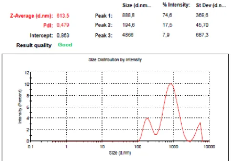
2.3.4- DINAMIC LIGHT SCATTERING SIZE DETERMINATION 57
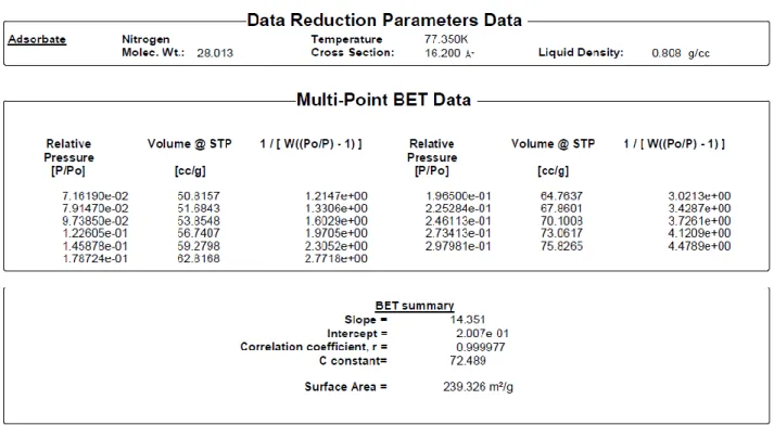
2.3.5- SURFACE AREA DETERMINATION (BET) 58
2.3.6- UV-VISIBLE SPECTROSCOPY 60
2.3.7- INDUCTIVELY COUPLED PLASMA OPTICAL EMISSION SPECTROMETRY 64
3- RESULTS AND DISCUSSION
3.1- PHOTOACTIVE TITANIUM DIOXIDE 663.1.1.1- PHOTO ACTIVITY TEST: METHYLENE
BLUE SOLUTION (Experiment 1) 73
3.1.2- TITANIUM DIOXIDE THERMAL TREATMENT, CHARACTERIZATION 78
3.1.2.1- PHOTO ACTIVITY TEST: METHYLENE BLUE SOLUTION 79
3.1.3- TITANIUM DIOXIDE HETEROCOAGULATION ON SILICA, CHARACTERIZATION (Synthesis 2) 80
3.1.3.1- PHOTO ACTIVITY TEST: METHYLENE BLUE SOLUTION 82
3.1.4- UV SOURCE COMPARISON 83
3.1.5- NOx PHOTOCATALYZED ABATEMENT, STATIC CONDITIONS (Experiment 2) 87
3.1.5.1- STATIC REACTOR - BLANK MEASUREMENT 87
3.1.5.2- STATIC REACTOR - CATALYST EFFECTIVENESS EVALUATION 89
3.1.5.3- SILANE/SILICA SUPPORT COATING (Synthesis 3) 91
3.1.6- NOx PHOTOCATALYZED ABATEMENT, FLUXING CONDITIONS (Experiment 3) 94
3.1.7- NOx PHOTOCATALYZED ABATEMENT, FLUXING CONDITIONS (Experiment 4) 98
3.1.8- NOx PHOTOCATALYZED ABATEMENT, FLUXING CONDITIONS (Experiment 5) 101
3.1.9- PHOTOVOLTAIC PANELS COATING (Experiment 6) 108
3.2- CALCIUM PHOSPHATES NANO-MICRO PARTICLES 115
3.2.1- CHARACTERIZATION OF CALCIUM PHOSPHATES 115
3.2.1.1- HYDROXYAPATITE CHARACTERIZATION (Synthesis 4 ) 115
3.2.1.2- BRUSHITE CHARACTERIZATION (Synthesis 5 ) 118
3.2.1.4- BRUSHITE CHARACTERIZATION (Synthesis 7 ) 122
3.2.1.5- BRUSHITE CHARACTERIZATION (Synthesis 8 ) 124
3.2.1.6- BRUSHITE CHARACTERIZATION (Synthesis 9 ) 126
3.2.1.7- MONETITE CHARACTERIZATION (Synthesis 10 ) 127
3.2.1.8- MONETITE CHARACTERIZATION ( Synthesis 11 ) 129
3.2.1.9- MONETITE CHARACTERIZATION ( Synthesis 12 ) 131
3.2.1.10- β-TRICALCIUM PHOSPHATE CHARACTERIZATION (Synthesis 13-14 ) 133
3.2.1.11- BIOMIMETIC POROUS SCAFFOLD CHARACTERIZATION (Synthesis 15 ) 135
3.2.1.12- BIOMIMETIC POROUS SCAFFOLD CHARACTERIZATION (Synthesis 16 ) 137
3.2.2- CALCIUM PHOSPHATES FOR BIOMEDICAL DRUG DELIVERY 139
3.2.2.1- ANTICANCER Pt COMPLEXES PHYSISORPTION ON HYDROXYAPATITE ( Synthesis 17- 18 ) 139
3.2.2.2- ANTICANCER Pt COMPLEXES RELEASE FROM HYDROXYAPATITE ( Experiment 7 ) 142
3.2.3- CALCIUM PHOSPHATES FOR PHYTOTHERAPICAL DRUG DELIVERY 144
3.2.3.1- PHYTOTHERAPIC DRUGS DELIVERY TEST (Experiment 8) 144
4- CONCLUSIONS AND PERSPECTIVES 148
1
1-INTRODUCTION
1.1- NANOMATERIALS
In the 1959 at the annual meeting of American Physical Society, the Nobel prize Richard Feynmann gave the famous speech “ there’s plenty of room at the bottom”, that focused on the emerging interest towards nanoscale science. During the years, the scientific research addressed a growing interest to nanoscale manipulation and understanding, and nowadays nanomaterials are commercialized and used as commodity. According to the definition reported in [ISO/TS27678, Nanotechnology- Terminology and definitions, Sept. 2008], a nanomaterial is an object showing at least one dimension in the 1-100 nm scale. On the basis of this definition, a first classification of nanomaterials can be made, referring to their dimensionality:
Zero dimensional materials ( nanocrystals, nanoclusters, Quantum Dots )
One dimensional materials ( nanowires, nanotubes )
Two dimensional materials ( nanofilms, 2D arrays )
Three dimensional materials ( nanostructured bulk solids, zeolites, etc. ), even if not included in the nanomaterials definition, have to be mentioned.
Apart for the ambitious challenge that the synthesis and manipulation of such objects represents, the enormous attention drawn by this materials is certainly due to the unique features they shows. In fact, in virtue of their dimension, nanomaterials exhibit a dramatic change in their intrinsic properties compared to the bulk. A bulk material should have constant physical/chemical features regardless its size, but decreasing dimensions to the nanoscale, new size-dependent properties appears and became predominant. In particles of nanometric scale, the surface to bulk ratio is significantly higher than in macroscopic objects, and their properties are dominated by surface chemistry and physics.
Quantum phenomena like surface plasmon resonance in metals/semimetals, quantum size confinement in semiconductors and superparamagnetism in magnetic material,s become relevant and affect macroscopic properties observed in nanomaterials [J.T.Lue, Enc. Nanoscien. Nanotech., vol. 10, 1-46], such as:
2
Insulating properties
Size-tunable optical emission frequency
Field emission Electrical conduction Dielectric constant Quantum tunneling Magneto-resistance Ferromagnetic resonance
Linear optical properties
Non linear optical generation
Fig. 1 – Example of Size-tunable optical emission frequency from Quantum dots [images from: www.Sciencenews.org]
Nanoparticles are also characterized by a very high specific surface area values, which results in enhanced reactivity and enormous driving force for diffusion. This makes possible, for example, sintering processes performed at very low temperature compared to bulk melting point. In virtue of their huge potential, still poorly mastered, nanomaterials are beginning to find a role in practical applications, as summarized in the following table reported by Gaffet, 2011 (Tab. 1).
3
Tab. 1 – Main application fields of nanomaterials, [E.Gaffet, 2011]
Beside the enthusiasm generated by these promising technologies, an accurate and cautious evaluation of their effects on health have to be done. Their enhanced reactivity, their capability of migrate through tissues and cellular membrane and accumulate in certain organs may in fact cause health hazards and new pathologies. Among various proposed theories, recent publications refers mainly to two type of mechanism as the origin of specific toxicity of nanoparticles [J. Boczkowski, et al., 2010]:
Surface adsorption of biologically active molecules: because of their relevant specific surface area, nanoparticles can adsorb and retain biologically active molecules. Especially if those molecules are secreted in controlled quantities, such as growth factor, their sequestration may induce cells suffering or death.
Oxidative stress induction: metal nanoparticles can generate a relevant amount of free radicals on their surface, or induce their production by cells. Highly reactive radicals can attack and damage both cell’s walls or DNA, leading to inflammation reactions, fibrosis
4
or favor cancerous processes. Moreover, exposure to some kind of carbon nanotubes may cause similar damages to those induced by asbestos.
Overall, actual data about specific nanoparticles toxicity are limited. It appears actually difficult to fully understand the biological effect of such reactive and mobile particles, and mostly to determine their long term effects.
5
1.1.1- HETEROGENEOUS CATALYSIS USING NANOMATERIALS
Particular attention to nanomaterials have been given by the science of heterogeneous catalysis. Great majority of currently used catalyst are in fact solids, and unique behaviors of nanosized solid materials are crucial to improve efficiency or sustainability of many catalytic processes.
First and essential step in every heterocatalyzed reaction is the adsorption of reactants molecules on catalyst surface. Mainly two types of interaction can occur between adsorbent and adsorbate:
Physisorption, characterized by weak interactions mainly determined by Van der Waals forces, ranging from 2 to 10 kcal/mol in energy. Physisorption produces only small perturbations to the adsorbate’s electronic structure.
Chemisorption, characterized by strong interactions ( 15 to 100 kcal/mol of energy ) occuring between adsorbent and adsorbate, which share the electron density. Heavy perturbations are produced to adsorbate’s electronic structure, and bonds breaking may occur concomitantly with the adsorption.
Key parameters for reactions involving such processes are transport phenomena, dispersion and, primarily, surface chemistry. In particular, surface chemistry play a major role in determining physical/ chemical phenomena occurring at the interface of the two phases. For example, at the surface of crystalline solids the lattice regularity is interrupted, determining a distortion in the electronic band structure and resulting in an interface characterized by a higher free energy compared to the bulk. Furthermore, defective structures often occur at the border surface, and defects may generate different reactivity sites. In virtue of their high specific surface area values and high surface to bulk ratio, nanomaterials are preferred candidates to cover the role of heterogeneous catalysts. Higher reactivity and higher number of disposable active sites guarantees relevant advantages compared to conventional macroscopic catalyst [Fukui, et al., 2004; Zalesskiy, et al., 2012] as:
increased efficiency and higher conversion rates;
higher retention of catalytic activity after recycling;
6
In order to ensure nanoparticles catalytic behavior and avoid aggregation phenomena resulting in a loss of activity or uncontrolled losses of nanoscaled material, stabilization technologies are applied. Nanoparticulate metals are commonly stabilized in solutions by functionalization steps involving ligands, polymers or olygomers [Roucoux, et al., 2002]. Otherwise nanocatalysts can be anchored on a support which usually is a solid characterized by a high surface area. The catalyst support may be inert or have a role in the reaction [Ma, et al., 2006.].
7
1.2- SEMICONDUCTOR MATERIALS
The energy and distribution of electrons in a solid material are described by the band theory that considers the quantum energy level and wave functions of an electron in a large periodic lattice of atoms. On an isolated atom, an electron occupies atomic orbitals, defined by discrete energy levels. When atoms combine, , new wave functions (molecular orbitals) each one characterized by a discrete energy level, are obtained, from the overlapping of atomic orbitals . In the case of solids, Avogadro’s numbers of atoms overlaps their orbitals producing a massive number of molecular orbitals. By increasing the number of atoms the energy levels related to molecular orbitals became increasingly dense, until they became so closer to lose their discrete character, being considered a continuum. What arises are the so called bands, i.e. regions of allowed energies for the solid electrons, and band gaps, i.e. unoccupied regions of prohibited energies, that separate bands. This theory gives a simplified model of solid materials based on the
assumption of an infinite homogeneous system of static potential where an electron moves), but is useful to explain some phenomena, like the conduction in solids. By filling bands with
electrons starting from the lower energies, the highest energy occupied band is called the “valence band” containing the outermost electrons, while the lowest unoccupied will be the “conduction band”. Dependently on the lattice structure and the nature of the atoms, the valence and conduction bands may be separated by a band gap of variable amplitude. On the basis of the width of this band gap, materials are classified in conductors, semiconductors or insulators. A more accurate description of bands filling is introduced the by Fermi level definition
according to which at the thermodynamic equilibrium, the probability for a state of a given energy E to be occupied by an electron is expressed by the Fermi-Dirac distribution:
where kB is the Boltzmann’s constant, T is the temperature in Kelvin° and EF is the Fermi energy. The Fermi energy defines the energy of the highest occupied level in a fermions system at 0 °K, considering Pauli’s exclusion principle. For temperatures above zero, the Fermi-Dirac distribution describes the electron occupancy of the states while the Fermi level indicates the energy level having a probability equal to ½ of being populated. This probability, and in consequence the electron density, rapidly decreases for the energy levels higher than EF and
8
increases for the lower levels. By coupling Fermi-Dirac distribution with the band theory, a more accurate description of solids conduction behavior can be done:
In a Conductor (metal or semimetal), the Fermi level lies inside one or more superimposed allowed bands. This determines a partial occupancy of that band and as a consequence its charge mobility behavior.
In semiconductors the Fermi level lies inside the band gap between valence band and conduction band. The band gap of semiconductors is not very wide, like for Silicon (1.21 eV), for this reason electrons can be promoted from the occupied valence band to the unoccupied conduction band. Population of states higher in energy requires thermal or photoinduced excitation, that have to provide to electrons an amount of energy equal or higher to the band gap. For this reason, the conductive character of thermal semiconductors is shown only at high temperature, while at low temperature the conduction band is not populated.
In insulator, like in semiconductors, the Fermi level lies inside the band gap between valence band and conduction band. Unlike semiconductors, the wide separation of the band gap makes impossible to obtain a sufficient population of conduction band to perform efficient charge transport.
Charge transfer may occur in consequence of two different mechanisms. Each electron promoted to the conduction band creates an empty and positive hole in the valence band. While electrons are the effective charge carriers moving through the partially occupied conduction band, the lack of charge in valence band creates a different mechanism of charge transport: nearby electrons move to fill the hole creating new gaps, and so on. The result is a “motion of gaps” acting as positive charges freely moving within the valence band. Conduction in a solid can be determined by one or both this phenomena. Moreover, some materials can be turned in semiconductors by doping with different atoms: extrinsic semiconductors are obtained by purposely adding conduction electrons ( n-type doping ) or valence holes ( p-type doping ) to the structure. The presence of defects in a crystalline solid may affect its properties both locally or overall. It is possible in fact that a local change in electron-hole recombination efficiency may determine an higher amount of disposable charge carrier for the whole solid, or act as preferred sites of interaction between electron-hole couples and other molecules adsorbed on the solid’s surface.
9
1.3- TITANIUM DIOXIDE
Titanium dioxide is an inorganic semiconductor material actually representing one of the most known, studied and important material that find application in a wide range of fields. Relevant features responsible of such interest toward this material are its chemical stability, non toxicity, relatively low production costs and manageability together with its useful optical, chemical and physical properties. For example, Titanium dioxide powder shows one of the highest reflective index value coupled with strong hiding power and high degree of whiteness, making it an excellent industrial pigment. In addition, it can be easily dispersed in solvents or aqueous media, justifying its wide applicability in many fields as paints, ceramic, plastic , food, pharmaceutical and cosmetic additive. Recently, Titanium dioxide pigment production through the world is estimated in four million tons per year [ Kronos international, 1996]. From 60s, Titanium dioxide found a leading role in many other technological applications, especially in energy and environmental fields, due to its peculiar physical-chemical features as photoactive semiconductor [A. Fujishima, 1999], [K. Hashimoto, et al., 2005]. Crystalline Titanium dioxide can be found at least in eight different polymorph structures. In nature it is present in four minerals: Rutile, Anatase, Brookite and the rarest and less known Columbite-structured TiO2. In addition to these, Titanium dioxide shows a rich phase diagram at elevated pressure, crystalline structures similar to Baddelayite, Cotunnite, Pyrite and Fluorite have been described in literature by high pressure coupled techniques [ T. Zhu, et al., 2014 ]. Among the commonly occurring polymorphs the most thermodynamically stable form and also the most abundant is Rutile, while Brookite and Anatase are metastable phases and may be thermally converted into Rutile.
10
1.3.1- POLYMORPHS DESCRIPTION
Rutile
In nature Rutile is found as a mineral mainly composed of Titanium dioxide, that may contain up to 10% of Iron, and relevant amount of Niobium and Tantalium. Its name comes from the Latin word “Rutilus” because of the deep red color observable in some specimen (Fig.2a). Rutile can be found in metamorphic or igneous rocks formed at high temperatures and pressures. It crystallizes in a Tetragonal crystal system with cell parameters of a=b= 4.587 Å, c= 2.954 Å, an space group P42/mnm. The base for this structure is a Titanium atom coordinated by
six oxygen atoms arranged in a distorted octahedron, resulting in two different Titanium-Oxygen bond lengths (Fig.2b).
(a) (b)
Fig. 2 – Rutile mineral image (a) and crystalline cell schematization(b), Titanium atoms are represented as blue spheres, Oxygen atoms are represented as red spheres [www.minerali.it, T. Zhu, et al., 2014]
Rutile is a direct band gap semiconductor, with an experimentally measured band gap of 3.3 ± 0.5 eV [Y. Tezuka, et al., 1994]. However, it is known that Rutile exhibits a scarce activity as photocatalyst and is mainly used in Titanium production and as pigment. In fact, fine powders of Rutile show one of the highest reflectivity index among materials and a bright white color, features that make it widely used in the production of paints, plastic, refractory ceramics, paper, food and cosmetics. In fact, since the nanoparticles of Rutile are transparent to the visible light, but strongly absorb UV radiation, Rutile is also used as screen to protect skin from UV hazards.
11
Brookite
Brookite is a natural polymorph, sometimes found together with Rutile in a epitaxial face relationship. Like Rutile, it shows a high reflective index, modest Mohs hardness and brownish to red coloration due to metal impurities (Fig.3a). It crystallizes in a Orthorhombic crystal system, with lattice parameters of a = 9.263 Å, b = 5.510 Å, c = 5.167 Å, and a space group Pbca. The brookite structure is built up of distorted octahedra with a Titanium ion at the center and oxygen ions at each of the six vertices. Each octahedron shares three edges with the adjoining ones ( Fig.3b)
(a) (b)
Fig. 3 – Brookite mineral image (a) and crystalline cell schematization (b), Titanium atoms are represented as blue spheres, Oxygen atoms are represented as red spheres [www.minfind.com, T. Zhu, et al., 2014]
Like Rutile, Brookite is a direct band gap semiconductor, with a calculated band gap of 3.86 eV [Y. Tezuka, et al., 1994]. However, like in the case of Rutile, Brookite exhibits a negligible activity as photocatalyst. Because of its rare occurrence, there are not specific application for Brookite.
12
Anatase
Anatase naturally occurs as little, blue crystals, often showing sharply developed octahedral geometries (Fig.4a). It crystallizes in a Tetragonal crystal system with cell parameters of a=b= 3.785 Å, c= 9.512 Å, an space group I41/amd. Also this structure is based on a Titanium atom
coordinated by six oxygen atoms arranged in a distorted octahedron (Fig. 4b).
(a) (b)
Fig. 4 – Brookite mineral image (a) and crystalline cell schematization (b), Titanium atoms are represented as blue spheres, Oxygen atoms are represented as red spheres [www.pinterest.com, T. Zhu, et al., 2014]
Anatase is an indirect band gap semiconductor, with an experimentally measured band gap of ≈ 3.2 eV [Y. Tezuka, et al., 1994]. Anatase shows the highest photoactivity among the three most abundant polymorph, for this reason Anatase and its application as photocatalyst have been deeply investigated. An explanation of its highest photoactivity compared to Rutile have been recently proposed by Luttrell, et al., 2014. First of all, Anatase shows an indirect band gap smaller than its direct band gap. Semiconductors with indirect band gap usually exhibit longer charge carriers life time compared to direct band gap ones. This is a consequence of the prohibited radiative recombination of conduction electrons and valence holes. Longer electron-hole pairs lifetime increases their availability in surface reactions. In addition, Anatase has a band gap larger than Rutile and it may raise the valence band maximum to higher energy levels relative to redox potentials of adsorbed molecules. This can increase the “oxidation power” of electrons toward adsorbed molecules. Lastly, in addition to exciton lifetime, the exciton mobility play a relevant role. It have been found that in Anatase along certain crystallographic
13
directions a major bulk transport of excitons to the surface occurs, drastically increasing electrons and holes participation to surface reactions. It is relevant to mention that phase mixtures demonstrates synergic effects, providing higher photoactivity than pure phases [Luttrell, et al., 2014]
1.3.2- PHOTOCATALYSIS MECHANISM IN SEMICONDUCTOR MATERIALS
Titanium dioxide, as previously reported, is a semiconductor material. Band gap values for the two most known polymorps, Rutile and Anatase, are 3.02 eV and 3.20 eV, respectively. By referring to Plank’s law:
E = hν = h
where E is the energy ( J), h is the Plank’s constant, c is the speed of light in vacuum and λ is the wavelength in n,
it is possible to calculate the wavelength of an electromagnetic radiation bringing enough energy to overcome the band gap, which results in about 410 nm for Rutile and 386 nm for Anatase. In fact, both Anatase and Rutile shows an intense absorption edge in correspondence of such wavelengths, in the Ultraviolet region of the spectrum. The absorption of a photon of this specific wavelength ( or shorter ) may result in the promotion of an electron from the valence to the conduction band, determining the generation of an electron-hole couple, or exciton. Generated electrons and holes can follow different paths: recombination is surely the preferred way because of its fast kinetics. A conduction electron and a positive valence hole annihilate each other, giving back an amount of energy equal to the band gap. Recombination may occur both by radiative or non-radiative way ( thermal excitement). A charge carrier, i.e. electron or valence hole, that not undergoes immediate recombination, may migrate through the solid, usually following specific crystallographic directions [T. Luttrell, et al., 2014]. Conduction electrons and valence holes reaching the solid surface can interact with adsorbed
14
molecules, causing redox processes in virtue of their potential of + 2.53 V and – 0.52 V, respectively, versus the Standard Hydrogen Electrode ( SHE ) at pH 7.00. By surface redox reactions, a cascade of radicals is produced. The major active radicals are produced by reaction with adsorbed Water and Oxygen molecules, resulting in the production of:
Hydroxyl radicals, OH. ( + 2.27 V vs SHE )
Superoxide ions, O2.- ( -0.28 V vs SHE )
Hydrogen peroxide H2O2 ( + 1.35 V vs SHE )
Fig. 5 – Schematization of electron-hole couple generation and radical production
Formed radicals can remain adsorbed on catalyst surface or migrate by diffusion mechanisms, and be involved in reactions with other molecules. It has been reported that the strong potentials exhibited by the charge carriers migrating on the solid surface and the reactive radical species can degrade several class of molecules, both organic and inorganic. In general, the degradation is slower for aliphatic compounds compared to oxygenated and aromatic molecules, especially those having an electron donor substituent, capable of activating the aromatic ring toward OH. radical electrophilic attack [J. M. Hermann, 1999] The final product of such reactions are low weight, stable, oxidized molecules. In particular, organic compounds are converted to CO2 and
H2O, Nitrogen compounds and Nitrous oxides to Nitrates and nitric acid, Sulfur compounds to
15
In addition, reactive species produced on catalyst surface shows high cytotoxicity, determining an effectiveness in bacterial load abatement and surface sanification. Due to this relevant properties, Anatase Titanium dioxide and a small family of similar photoactive semiconductors ( chalcogenide oxides or sulfides ) have found many technological applications in pollutants removal and environmental solutions [A. Fujishima, 1999], [ K. Hashimoto et al., 2005]. Main fields of environmental interest are nowadays i) water treatment, ii) air purification and iii) water disinfection. Actually, the bigger limit is represented by the wide band gap of Titanium dioxide, that determines the necessity of UV photons to promote the electron-hole generation. To overcome this limit, many ways have been reported to shift the band gap energy to longer wavelengths, in the visible spectrum. Unfortunately, heavy chemical modifications are necessary to obtain and absorption redshift, such as non-metal doping (mainly Nitrogen doping), or expensive techniques like noble metals layer deposition [M. Pelaez et al., 2012].
16
1.4- CALCIUM PHOSPHATES
Calcium phosphates are minerals and also the main components of calcified tissues in vertebrates. For example bones and dentin are composed of more than the 70 % of Hydroxyapatite, a calcium phosphate containing an hydroxide group, intergrowth with organic molecules, mainly collagen. Despite Hydroxyapatite and other Calcium phosphates are naturally occurring minerals, their mechanical and morphological features cannot be compared to biogenic materials, even if characterized by the same elemental composition. Biogenic calcified tissues are in fact highly sophisticated composite materials, determined by an high degree of hierarchical organization. In bones, the Hydroxyapatite phase is non stoichiometric, carbonate substituted and poorly crystalline [Roveri, et al., 2010]. Inorganic lamellar shaped microstructures are intimately intergrowth with aligned collagen fibrils, guided by epitaxial surface recognition with fibrils charge pattern. Composite structural motifs hierarchically develop until defining both macroscopic cavities of trabecular bone and dense cortical bone, allowing vascularization and cell colonization. Every detail in structure and composition is functional to determine mechanical strength, lightness, reliability and adaptability requested to the bone tissue. Comparable properties are far to be obtained by the only mineral phase itself. Such degree of sophistication is obtained in biosynthesis by a fine spatial control of chemistry at nanoscale level. Inter-intra cellular spaces, membranes, vescicoles delimitates spaces in which biomineralization can be controlled nearly at single atoms level.
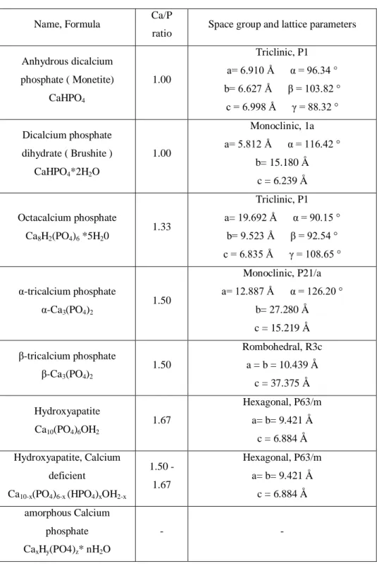
Obviously Calcium phosphates are completely biocompatible and, in certain cases, shows good bioreabsorbiblity. Due by their almost perfect behavior in the interaction with the biological environment, Calcium phosphates are an elective material for biomedical applications. For this reason a relevant amount of literature has been produced concerning their synthesis, characterization and appliance. Since the beginning, the major interest was addressed to these crystalline phases characterized by a Calcium to Phosphor molar ratio comprised between 1 and 2. Outside this range, Calcium phosphate phases shows high solubility and acidic or basic features, not suitable for a biological environment destination. In particular, the crystalline phases fulfilling this requirement are: Anhydrous dicalcium phosphate ( Monetite ), dicalcium phosphate dihydrate ( Brushite ), octacalcium phosphate, α-tricalcium phosphate, β-tricalcium phosphate, Hydroxyapatite, with the inclusion of a defective Calcium deficient Hydroxyapatite
17
and amorphous Calcium phosphate [F. Chen, et al., 2012]. A brief description of these phases is reported in Tab.2.
Name, Formula Ca/P
ratio Space group and lattice parameters
Anhydrous dicalcium phosphate ( Monetite) CaHPO4 1.00 Triclinic, P1 a= 6.910 Å α = 96.34 ° b= 6.627 Å β = 103.82 ° c = 6.998 Å γ = 88.32 ° Dicalcium phosphate dihydrate ( Brushite ) CaHPO4*2H2O 1.00 Monoclinic, 1a a= 5.812 Å α = 116.42 ° b= 15.180 Å c = 6.239 Å Octacalcium phosphate Ca8H2(PO4)6 *5H20 1.33 Triclinic, P1 a= 19.692 Å α = 90.15 ° b= 9.523 Å β = 92.54 ° c = 6.835 Å γ = 108.65 ° α-tricalcium phosphate α-Ca3(PO4)2 1.50 Monoclinic, P21/a a= 12.887 Å α = 126.20 ° b= 27.280 Å c = 15.219 Å β-tricalcium phosphate β-Ca3(PO4)2 1.50 Rombohedral, R3c a = b = 10.439 Å c = 37.375 Å Hydroxyapatite Ca10(PO4)6OH2 1.67 Hexagonal, P63/m a= b= 9.421 Å c = 6.884 Å Hydroxyapatite, Calcium deficient Ca10-x(PO4)6-x (HPO4)xOH2-x 1.50 - 1.67 Hexagonal, P63/m a= b= 9.421 Å c = 6.884 Å amorphous Calcium phosphate CaxHy(PO4)z* nH2O - -
Tab. 2 – Summary description of Calcium phosphates characterized by a Calcium to Phosphor molar ratio comprised between 1 and 2
18
Among the reported crystalline phases, octacalcium phosphate, tricalcium phosphate (α and β ), Hydroxyapatite and the amorphous calcium phosphate are particularly suitable for biomedical application. This Calcium phosphates are similar to biogenic calcified tissue components, so they are not recognized as foreign material in the body and can integrate into living tissues by bone-remodeling processes.
1.4.1- CALCIUM PHOSPHATES IN BIOMEDICAL APPLICATIONS
The main usages of calcium phosphates in biomedicine are:
Hard tissue engineering
As a consequence of traumatic events, invasive therapies, degenerative diseases, a loss of structural hard tissues may happen. Fast replacement of this tissue can accelerate healing while providing an increase in patients ease. Characteristics of an ideal bone replacement are: biocompatibility, bioreabsorbiblity, osteogenesis and osteoconduction capability obtained by optimal cell colonization, and obviously mechanical strength. Biomaterials science extensively studied Calcium phosphate base materials as bone filler or bone substituent. Many techniques have been developed to produce solid materials containing micro and macro porosity ( useful for cell colonization ) , void structures, 3D architectures, in order to constantly improve body response to their appliance. Nanomaterial science applied to hard tissue engineering introduced relevant improvements. Due to the similar dimensions with respect to the inorganic components of calcified tissues and to the enhanced surface reactivity, nanosized calcium phosphates reveal: better osteoconduction/ osteoinduction properties, enhanced interaction with organic materials, better sinterability and mechanical properties [F. Chen, et al., 2012].
Drug/gene delivery
After implantologic surgery, any pathological situation ( infection, inflammations, etc ) unfavorably affects the performance of the implant in terms of healing and resorption process. To avoid these phenomena, implanted biomaterials may be “charged” with drugs, acting as carriers responsible of local drug release. Calcium phosphate biomaterials have been
19
promisingly studied as drug delivery systems, both as drugs releasing bone substituents and drug carrier nano-micro particles [E. Verron, et al., 2010; F. Chen, et al., 2012]. In particular, Hydroxyapatite is capable to bound a variety of molecules and most therapeutic agents under physiological conditions [N.Roveri, et al., 2010]. E. Verron, et al., 2010, reported that Hydroxyapatite bone cements revealed promising issues in local delivery of drugs characterized by low efficiency of systemic administration. Hormones, growth factor, bone morphogenic protein and antibiotics characterized by short half-time have been successfully administered by Calcium phosphates bone substituent, while bisphosphonate drugs can be strongly adsorbed on Calcium phosphates carriers [P. Pascaud et al., 2014]. In general, local drug delivery could reduce side effects and improve the efficacy of existing drugs. By adjusting the properties and the morphology of the carrier, addressing and rate of drug release may be controlled by various mechanisms.
Hydroxyapatite, provides a surface chemistry that facilitates adsorption of organic compounds
(i.e. proteins ) as well as charged inorganic particles [R. K. Singh, et al., 2013]. K. Wang et al, 2012, investigated the adsorption mechanism of proteins on bioceramics, suggesting the relevant parameters affecting these phenomena. For an example, it was found that large molecules near their isoelectric point adsorb readily, because of the wider variety of disposed charges capable to match with surface Calcium and phosphates ions. It have also been demonstrated [I.S. Harding, et al., 2005] that HA faster accumulates positive charge below the point of zero charge than it accumulates negative charge above it. In this work focused on the adsorption/desorption processes the authors reported that in many conditions phosphate groups will predominate at the HA surface. On this basis mechanism for surface adsorption has been proposed to be deprotonation of surface HPO42- sites and subsequent adsorption of cations to the
lattice surface site ( if cation is Calcium, lattice growth occurs ). [N. Lyczko, et al., 2014], also, proposed and reported a study on the capability of Hydroxyapatite to link, retain and sequestrate heavy metals from aqueous media, for environmental purposes.
20
1.5- AIM OF THE THESIS
Inorganic nano and micro particles retrieved along years large interest, and abundance of literature is nowadays available investigating their potentiality in many fields. The control and tuning of their properties, joined with their intrinsic behavior allow to obtain versatile, stable, efficient technological materials. Relying on already well known properties of inorganic materials, the aim of this thesis is to synthesize specific inorganic nano and micro particles and to develop and optimize working applications involving their use. In particular this research work has been focused on Titanium dioxide and Calcium phosphate materials. Such materials are purposely synthesized with the aim of showing effectiveness in desired application. Particular attention is given to the surface properties and particle dimensions. The focal point and main challenge of this work is to retrieve relevant performances while strongly looking for the high simplicity, environmental low impact and economical affordability of the synthesis and application. The syntheses have been designed and performed in non-toxic and non-hazardous solvents and the use of heavy metals or reaction additives, such as surfactants, stabilizers, capping agents have been avoided or limited. Moreover, the used reaction conditions were as much as possible mild and safe, as proposed by the “green chemistry” principles. Also the design and development of applications and prototypes must take into account the environmental impact, working simplicity and economical affordability.
In particular, environmental and energetic fields applications are reported for photocatalytic Titanium dioxide nanoparticles. Optimizing the parameters for an efficient and massive radical generation process, Titanium dioxide nanoparticles have been applied in gaseous pollutant abatement. Subsequent prototypes have been built and tested with the aim of reduce the emissions of a working plant. In addition, photoactive Titanium dioxide have been deposited on photovoltaic panels with the purpose of exploit their self-cleaning properties in order to enhance their efficiency.
By pointing on adsorption capabilities, synthesized sub-micrometric Calcium phosphates showing high surface area have been tested as drug carriers in two different applications. Hydroxyapatite nanoparticles have been used, dispersed into their own mother solution to avoid aggregation phenomena induced by drying, to prepare an injectable suspension for local anticancer drugs delivery. Hydroxyapatite nanoparticles and Brushite microparticles have also
21
been proposed and tested for an innovative use as agricultural drug carriers for phytotherapics delivery, similarly to biomedical applications. Nowadays in fact, Calcium phosphates are used in agriculture only as phosphor containing fertilizers.
22
2- EXPERIMENTAL SECTION
2.1- PHOTOACTIVE TITANIUM DIOXIDE
2.1.1- TITANIUM DIOXIDE SOL-GEL SYNTHESIS ( Synthesis 1 )
The photoactive Titanium dioxide have been obtained by hydrolysis/polycondensation of an alkyl-oxo Titanate in aqueous solution under controlled conditions; Isopropyl alcohol have been added as stabilizing and capping agent in order to control the hydrolysis and crystal growth rate. Titanium (IV) isopropoxide have been chosen as Titanium (IV) source and 0.3 mol of this reagent have been dissolved in 300 ml of Isopropyl alcohol in a well dried flask and stored capped. At the same time 900 ml of distilled water are heated to 80°C in a three-necked flask. The Titanium alkyl-oxide isopropanol solution is now transferred into a dropping funnel and slowly added dropwise to the aqueous media under vigorous stirring. To avoid the uncontrolled reaction of Titanium isopropoxide with water vapor on the dripper tip causing the formation of solid aggregates and irregular flow, a mild air souffle is directed to the droplets line. The reaction occurs immediately, forming a white suspension of Titanium dioxide nanoparticles in the water phase. After the dropping the reaction is maintained at 80°C under stirring for 3 hours. Part of the hydro-alcoholic suspension is now centrifuged at 7000 rpm for 10 minutes, the precipitate is collected and dried at 70°C for 4 hours, then finely crushed in a mortar. The synthesis have been performed again by varying the alkyl-oxo-Titanate concentration ( 1/10 proposed molar amount ) in order to affect the average size of crystallites aggregates in suspension.
Fig. 6 – Reaction scheme of Titanium (IV) isopropoxide hydrolysis/polycondensation reaction leading to Titanium dioxide formation
23
Reagents:
Ti[OCH(CH3)2]4, Sigma Aldritch, reagent grade, pur. 98%
(CH3)2CH2OH, Sigma Aldritch, pur. >99%,
2.1.1.1- TITANIUM DIOXIDE THERMAL TREATMENT
Dry solid Titanium dioxide powder have been finely grounded in a mortar and heat treated to increase crystallinity, trying to enhance photoactivity [S. Sakka, 2005 ]. 5.0 grams of powders are placed in an Alumina crucible and heat treated for 1 hour at 420°C after a 5°C/min ramp in air atmosphere. Heat treatment performed with Thermal system TSH 17/50/300 elite limited tubular oven.
2.1.1.2- TITANIUM DIOXIDE HETEROCOAGULATION ON SILICA ( Synthesis 2 )
To improve Titanium dioxide photocatalytic behavior by avoiding aggregative phenomena resulting in loss of active surface area, Titanium dioxide nanoparticles have been adsorbed on silica microparticles by heterocoagulation. 1.0 g of fumed silica are disperded in 100 ml bidistilled water and kept under mild stirring in a plastic beaker. A small amount of 0.01 M ammonia solution is added to reach pH 5.00. Then, 50 ml of Titanium dioxide hydro alcoholic suspension prepared as previously described, are added dropwise and the mixture kept under slow stirring for 30 minutes. The solid phase is now filtered and washed with distilled water to remove Ammonia and excess of Titanium dioxide, and dried 10 hours at 40 °C.
Reagents:
SiO2 fumed silica, Sigma Aldritch, surf. Area 175-225 m2/g, pur. 99,8%
NH4OH, 28-30% solution in water, Sigma Aldritch, ACS reagent grade
24
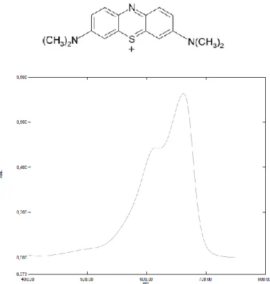
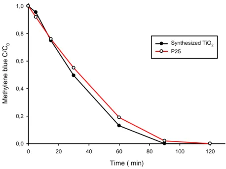
2.1.1.3- PHOTOACTIVITY TEST: METHYLENE BLUE SOLUTION (Experiment 1)
3.13*10-5 mol Methylene blue (3,7 bis-(dimethylammino)phenazationium chloride) are dissolved in 100 ml distilled water and the solution is stored in dark. 50 mg of Titanium dioxide powder are dispersed in 90 ml distilled water by bath sonication for 15 min, then 5 ml of the methylene blue solution are added keeping the mixture under stirring to avoid aggregation/ sedimentation of titania, and finally the solution volume is adjusted to 100 ml. The mixture is placed in a dark box under vigorous magnetic stirring, and a 3 ml sample of suspension is transferred in a glass cuvette ( 1 cm optical path) to collect the UV-Vis spectrum at the time zero. To minimize baseline fluctuations given by light scattering the spectrum is collected in a range of 720 -540 nm and the signal is set equal to zero at λ=720 nm for each measure. In fact, aggregated Titanium dioxide particles in suspension scatter visible light causing a slight turbidity of the solution. Moreover, the aggregation phenomena affect particle size during the measure changing the baseline value with time. After collecting the spectrum versus a blank of distilled water, the sampled amount is transferred back into the mixture to keep the initial volume. Inside the box, the mixture is then irradiated with a UV source (typically high pressure Hg vapor lamp, λ =365 nm, 25 W) placed at 15 cm distance to the suspension surface still under stirring. The sampling procedure is repeated and spectra are collected at various time intervals until 180 minutes. The described setup allows to work easily with simple equipment, and producing reproducible data characterized by good signal to noise ratio within the absorbance linearity range of the analyte in reasonable times. In order to identify the most performing commercially available light source, this test have been repeated using a 365 nm high pressure Hg lamp, a 254 nm low pressure Hg lamp and a set of 365 nm LED; the data obtained have been compared and the effective emission spectra of this sources recorded and related to the results.
Reagents:
Methylene blue (3,7 bis-(dimethylammino)phenazationium chloride), Sigma Aldritch, pur. >97%
25
Tested lamps specifications:
High pressure Hg lamp, λ emission = 365 nm, power 25 Watt, UVL-225D Mineral lamp model, UVP
Low pressure Hg lamp, λ emission = 254 nm, power 25 Watt, UVL-225D Mineral lamp model, UVP
LED system, λ emission = 365 nm, composed by 160 LEDs for a total 22.6 Watt, purposely built by DELLED
2.1.2- NOx PHOTOCATALYZED ABATEMENT
2.1.2.1- NOx PHOTOCATALYZED ABATEMENT, STATIC CONDITIONS (Experiment 2)
The performances of prepared Titanium dioxide catalyst in photocatalitic degradation of gaseous nitrous oxides ( NO and NO2 mixture, commonly indicated as NOx ) have been at first
tested in static conditions. A sealed glass box of the approximate volume of 8 liters have been equipped with a 9 Watt low pressure Hg vapor lamp ( λ=254 nm, UV ) and a NOx portable analyzer ( CROWCON GAS-PRO IR 452164/03-001 equipped with IR detector ). Pictures of experimental apparatus are reported in Fig.7.
26
Fig. 7 – Pictures of experimental apparatus used for static NOx photocatalized abatement tests
At first the chamber have been filled with NOx certified solution to the final concentration of approximately 50 ppm ( total NOx ), but some air have been allowed to remain inside. The NOx concentration have been monitored for 90 minutes to evaluate the spontaneous equilibration reaction between the two nitrous oxide species and the environmental oxygen, and to avoid the presence of gas loss in the system as well.
Due to the fact that NOx gaseous solution used for the reported tests is mainly composed of the mono oxidized specie NO, oxidation reaction spontaneously occurs when mixed with environmental oxygen. Equilibrium conditions between NO, O2 and forming NO2 are reached
within 60 minutes, as visible in Fig. 8, after that the analytes concentrations can be considered constants. Following this results, each subsequent test is performed after an equilibration delay of 60 minutes, in order to cut off this phenomena from affecting catalysis data measurement.
27 Time ( min) 0 20 40 60 80 Co n c. (pp m ) 0 10 20 30 40 50 60 NO2 NO
Fig. 8 – Concentration variations of NO and NO2 within a sealed chamber, in absenceof UV irradiation or catalyst due to equilibration of NO, O2 and forming NO2.
In order to separate and evaluate the single role of different mechanism contributing to NOx scavenging from the system, the UV induced photolysis have been measured. The test chamber have been filled with NOx certified solution to an approximate final concentration of 50 ppm ( total NOx ), leaving some air inside. The system have been sealed and left 60 minutes in absence of light to allow NO and NO2 to reach the equilibrium concentrations. After that the
UV source is turned on in absence of any catalyst and the NOx concentrations is monitored for 45 minutes. The data obtained are normalized and reported as percentage value, and referred as the blank for all subsequent tests involving catalysts.
A stainless steel net basket ( 8 cm lenght, 3.5 cm diameter, 45 µm mash holes ) is added to the chamber setup surrounding the UV lamp to act as catalyst support ( estimated disposable surface 60 cm2). The basket have been previously carefully cleaned by sonication in acetone and washed with water, dried and soaked in the Titanium dioxide suspension obtained via sol-gel synthesis, previously described ( Synthesis 1). After drying, the soaking is repeated for a better covering up of the surface. No adhesive or linker is added to the suspension and the catalyst particles are weakly grabbed to the metal surface, but the adhesion is sufficient to avoid material loss by shaking. Approximately 12 mg of active Titaniun dioxide are anchored to the support.
28
The test chamber so prepared have been filled with NOx certified solution to the approximate final concentration of 25 ppm ( total NOx ), leaving some air inside. The system have been sealed and left 60 minutes in absence of light to allow NO and NO2 to reach the equilibrium
concentrations. Then, the UV source is turned on and the NOx concentrations is monitored for 120 minutes.
Reagents:
NOx certified solution (gas mix from SIAD, NO = 80.0 ± 1.7 ppmvol, NO2 = 0.8
ppmvol, in Nitrogen)
TiO2 suspension produced by synthesis
2.1.2.1.1- SILANE/SILICA SUPPORT COATING (Synthesis 3)
In order to increase the catalyst adhesion on the solid support and improve the dispersion of the particles, Titanium dioxide is deposited on a silica covered substrate. The steel basket is carefully cleaned by sonication in acetone and water to remove the deposed catalyst, and dried. 67.0 ml of TEOS ( tetraethyl-oxy-silane) are placed in a 200 ml flask under mild stirring and heated to 35°C. 19.0 ml TMCS ( trimethyl-chloro-silane) are added and left mixing for 10 minutes. After that 37.5 ml of Isopropyl alcohol are added and left reaching the correct temperature. Meanwhile, 7.5 ml of Ammonia ( 30% solution in water ) are added to 22.5 ml isopropyl alcohol, transferred into a dropping funnel, and added dropwise to the silane mixture. The formation of a white mist, due to the gas-phase reaction between NH3 and HCl formed by
TMCS hydrolysis, and a white precipitate inside the flask can be observed. After the dropping the reaction is kept 5 hours at 35-40°C under mild stirring, then the white precipitate is filtered, the liquid phase is collected and taken up to 150 ml volume with isopropyl alcohol. The steel basket is now quickly soaked in the alcoholic silane mixture, excessive liquid is removed by shaking and finally gently sprinkled with fumed silica dust. The basket is then left aging for 72 hours at room temperature. After aging, silica dust in excess is removed by a air blow and the silica-coated steel basket is soaked in the Titanium dioxide hydro-alcoholic suspension obtained via sol-gel synthesis 1. After drying, the soaking is repeated to improve the covering up of the surface. The coated basket is then mounted in the test chamber filled with NOx certified
29
solution to reach the approximate final concentration of 25 ppm ( total NOx ), leaving some air inside. The system have been sealed and left 60 minutes in absence of light to allow NO and NO2 to reach equilibrium concentrations. After that the UVC source is turned on and the NOx
concentrations is monitored for 120 minutes.
Reagents:
Si(OC2H5)4, Sigma Aldritch, reagent grade, pur. 98%
(CH3)3SiCl, Sigma Aldritch, reagent grade, pur. >98%
NH4OH, 28-30% solution in water, Sigma Aldritch, ACS reagent grade
(CH3)2CH2OH, Sigma Aldritch, pur. >99%,
SiO2 fumed silica, Sigma Aldritch, surf. Area 175-225 m2/g, pur. 99,8%
NOx certified solution (gas mix from SIAD, NO = 80.0 ± 1.7 ppmvol, NO2 = 0.8
ppmvol, in Nitrogen)
TiO2 suspension produced by synthesis 1
2.1.2.2- NOx PHOTOCATALYZED ABATEMENT, FLUXING CONDITIONS (Experiment 3)
To approach the real conditions in which the photocatalytic system have to work, some degradation tests on fluxing gas have been carried out. A scale model of the real scrubbing tower have been purposely built in PVC plastic, and added of an electric powered fan to simulate the effective pressure and flow. Within the inner cavity of the drainpipe ( 100 cm length x 13 cm diameter ) a photocatalytic system is mounted according to the most effective setup identified by previous static tests. The tube have been lined interiorly with 40 mm thick glass fiber wool previously coated with Titanium dioxide ( by spraying nearly 500 ml of prepared hydro-alcoholic titanium dioxide suspension). When dried, a UV source is fitted in the
30
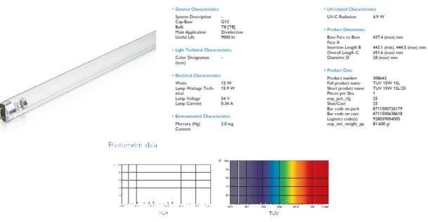
remaining cavity; the source consisted in two in-line mounted low pressure Hg lamp, emission λ= 254 nm, 30 W total power ( technical datasheet reported in Fig. 9). In order to increase as possible the catalytic surface, empty spaces of the tube have been filled with Titanium dioxide coated silica glass pieces, recovered from scraps ( approximate average size 20x30x5 mm). The so prepared catalytic tube is mounted on the scale-model prototype, and flow tests have been carried out with air to evaluate the working conditions and to avoid obstructing phenomena; by calculations the estimated flow is 8.5-10 m3/hour, and the travelling time of gaseous species trough the catalyst 5 to 7 seconds.
Fig. 9 – Technical datasheet of low pressure Hg lamp used in tests and prototypes construction
The prototype is tested to measure its effective capability of reduce the NOx concentration of a flowing by gas mixture. An NOx real time analyzer (CROWCON GAS-PRO IR 452164/03-001 equipped with IR detector) is applied to the prototype exhaust pipe ( after the fan) and a Nitrous oxide certified solution is blown into the input pipe. Because of the input pipe diameter ( 130 mm) and the strong suction, a relevant amount of environmental air is drawn and mixed to the NOx solution, making possible to obtain an exit top concentration of 14 ppm, only. A set of tests have been performed by repeatedly turning on and off the UV source while the gas mixture is flowing by the prototype and collecting data about the exit NOx concentration variations related to time.
31
Reagents:
NOx certified solution (gas mix from SIAD, NO = 80.0 ± 1.7 ppmvol, NO2 = 0.8
ppmvol, in Nitrogen)
TiO2 suspension produced by reported synthesis 1
2.1.2.3- NOx PHOTOCATALYZED ABATEMENT, FLUXING CONDITIONS (Experiment 4)
Because of the gas mix cylinder’s scarce capacity and low concentration, it appears difficult to obtain reproducible data; during the tests in fact NOx concentration tended to decrease and after only five set of test the NOx mixture pressure was over. Furthermore the concentrations value reached and gas composition was not truly representative of the effective output of the plant process on which the photocatalytic process have to be applied. The prototype have so been modified and directly connected to the plant’s exhaust chimney. Instead of loading the photocatalytic system in the narrow aspiration tube, the full width of the prototype’s central body is used; the internal exchange plastic bodies have been removed and at its place a sort of filtering layout is prepared by fitting three floors of stainless steel net perpendicular to the gas flow. A new type of catalyst is prepared and deposed on the net supports to a thickness of nearly 25 mm each floor. The catalyst consisted of scrap glass pieces taken from the glass recycling spinneret for negligible costs; the silica glass particle are nearly same size and shape (cube 4x4x4 mm), without sharp edges, showing an average weight of 0.158 g each. By simple calculations an average surface area of 6330 cm3 per kilograms is shown by this low cost, chemically inert support. Residual impurity (mostly metal pieces) are removed and the glass substrate is carefully washed with water and with an ammonia solution( pH 10); meanwhile 5 ml of concentrated HCl solution ( 38% w/v) are added to 5 liters of Titanium dioxide hydro-alcoholic suspension. The acidified Titania suspension is now spray-applied to the still wet glass pieces, previously spreaded on polypropylene sheets. After 24 hours drying glasses are collected
32
and mildly washed with water to remove excessive catalyst and ammonium chloride; 50 kg of glass supported catalyst were prepared, but approximately only half have been used in the prototype. The UV source has been improved as well, by increasing the total system power from 30 to 100 Watts disposing three lamps ( one each floor) parallel to the catalyst surface ( about 150 mm above this) and a fourth lamp perpendicular to these, crossing all the catalyst floors. The modified prototype was connected to the plant’s exhaust chimney, the fan turned on and the effective gas mix produced by anodizing process let flow by. Gas analysis was performed by a portable multi gas analyzer (LAND, LANCOM 4) capable of measuring eight different gas-phase analytes by electrochemical cells, including NOx. Placed the sampling probe at the prototype exhaust, a “white “ measurement have been carried out , showing the effective NOx emission profile along time related to a single plant process cycle. The UV source was then switched on and the measurement repeated, obtaining real data about NOx knocking down capability of photocatalytic prototype. Unfortunately the effective exhaust gas shown high corrosive features, quickly damaging the hand made electric wiring of UV lamps; for this reason was only possible just to turn on one of three displaced lamps, working with 30 Watts power, before a complete breakdown of electrical circuit. Furthermore the electric powered fan turned out to be undersized to overcome the intense sucking power of the plant’s chimney, leading to a low gas flow rate into the prototype. Nevertheless it was possible to obtain promising data on the photocatalyzed reaction on the real gas mixture.
Reagents:
NH4OH, 28-30% solution in water, Sigma Aldritch, ACS reagent grade
HCl, fuming >38% solution in water, Sigma Aldritch, ACS reagent grade
33
2.1.2.4- NOx PHOTOCATALYZED ABATEMENT, FLUXING CONDITIONS (Experiment 5)
In order to get closer to a pilot plant configuration, a new improved prototype was built enhancing catalyst displacement, UV irradiation and flow. A 300 mm diameter PVC tower was built and 20 catalytic floor have been made inside by glass fiber net, each one was charged with approximately 600 g of Titanium dioxide coated glass pieces disposed on the net support. Every catalytic floor was spaced 100 mm, and in the middle two compact UV lamp (9 watt, low pressure Hg vapor, emission λ= 254 nm) were placed. A most powerful fan was applied to the setup and the electrical wiring was completely related to the outside of flow tunnel; the assembled prototype resulting in a 2.2 meters catalytic tower was connected to the plant’s exhaust chimney, the fan turned on and the effective gas mix produced by anodizing process let flow by. Pictures of the complete prototype and particulars of the catalytic floor are reported in
34
(a) (b)
(c) (d)
Fig. 10 – Pictures of the complete prototype (b); particulars of catalytic floors without catalyst (a), loaded with catalyst (d) and UV irradiated (c)
After a purging time required by the huge amount of condensation liquid drained by the prototype from the plant’s chimney, a first set of tests have been carried out: the outcoming gases from the prototype have been sampled and analyzed following the official methods reported in “estensione del decreto ministeriale 25-08-2000 all.4 comma 2 D.M. 12-07-1990”. A bubbler is charged with 30 ml of 0.025 M Potassium permanganate and 1.25 M Sodium hydroxide solution and connected to the prototype tower and the gas is sampled to a flow speed of 0,5 liters/min for 30 minutes. A “white “ sample is collected with UV lights turned off, then the sampling procedure is repeated three times turning on: 10 UV lamps active on 10 catalytic


![Faites vos jeux! Gioco pubblico e società contemporanea: storia, implicazioni, prospettive, a cura di Ornella De Rosa, Editori Laterza, Bari 2018: [recensione]](data:image/gif;base64,R0lGODlhAQABAIAAAP///wAAACH5BAEAAAAALAAAAAABAAEAAAICRAEAOw==)