Different implant impression techniques for edentulous patients treated with CAD/CAM complete-arch prostheses: a randomised controlled trial reporting data at 3 year post-loading
16
0
0
Testo completo
(2) 326 . Pozzi et al. Implant impression techniques. Introduction An accurate and passive fit of the prosthesis has been suggested to be a clinical prerequisite for the long-term success of implant treatment1-3. Osseointegrated implants are rigidly connected to the host bone, lacking the inherent resilience of the periodontal ligament4. Misfit of the implant framework may result in an accumulation of bending moments and loading stresses, causing possible mechanical (loss of retention, fracture of the veneering material, screw loosening and framework fracture) as well as biological (bone remodelling, microdamage and loss of osseointegration) complications1-10. Horizontal fit discrepancy leads to bending stresses in the implant system, contributing to a major proportion of the distortion and biomechanical complications of prostheses8. Vertical fit discrepancies render the screws vulnerable to fatigue fractures and loosening because the preload is used to bring the matching surfaces at the prosthetic interface closer together8,10. This problem could be critical because the vertical direction of the distortion may be more likely to introduce preload in the implant8. The accuracy of fit of an implant prosthesis is affected by many variables, including the current impression techniques9, impression materials8,10, master cast pouring techniques11 and framework fabrication11-14. Furthermore, additional implant features (number, depth, angulation and connection type) may indirectly affect the accuracy of the impression15,16. Nevertheless, the impression technique remains one of the most important factors determining the accuracy of the implant impression9. There is no universally accepted clinical definition of passive fit4,17. Some authors have defined passive fit as the absence of strain development following framework fixation4. Others have considered a framework to be passively fitting when the gap between the framework and the abutment ranges between 10 μm and 150 μm2,8. Several time-consuming laboratory techniques have been proposed to achieve the most accurate clinical fit for metal implant frameworks; these include sectioning and soldering, laser welding, spark erosion with an electronic discharge machine (EDM), and bonding the framework to prefabricated. Eur J Oral Implantol 2013;6(4):325–340. cylinders or copings10,14. By facilitating the fabrication of implant frameworks milled from one piece of a homogeneous material, computer-aided design/ computer-assisted manufacturing (CAD/CAM) technology has overcome the problems of framework distortion and inaccuracy associated with conventional lost wax and casting techniques10,18-21. For the latter, there is an abundance of literature on CAD/CAM single crowns, fixed dental prostheses (FDPs) and complete-arch prostheses22-27. Nevertheless, the potential accuracy of modern CAD/ CAM manufacturing cannot be optimised without an accurate impression procedure, which is necessary for transferring details of the patient’s anatomy and the positions of the implants onto the master cast28-31. Recording the exact three-dimensional (3-D) positions of the implants is mandatory to deliver an accurately fitting prosthetic framework. Various implant impression techniques and materials are currently in daily practice. Square-shaped impression copings in combination with a custom-made open tray (the pick-up impression technique) have been recommended32-36 as superior to tapered impression copings and stock impression trays35-38. Nevertheless, the necessity of splinting the impression copings has been demonstrated in several investigations5,7,11,39-41. Brånemark2 stated that the implantsplinted technique is more accurate than the nonsplinted technique. Furthermore, low-shrinkage auto-polymerising acrylic resin and impression plaster are significantly more accurate splinting materials than dual-polymerising acrylic resin7,9,16,37,40,42. Despite some authors’ recommendations of plaster impressions for fully edentulous patients due to their satisfactory surface detail and excellent dimensional stability30,37, this technique has not gained popularity among clinicians, most likely due to the handling difficulties associated with overcoming anatomical undercuts. Therefore, polyether (PE) and vinyl polysiloxane (VPS) have been recommended for implant impressions9. The aim of this study was to compare the interimplant discrepancy of casts poured using two different implant impression techniques for completely edentulous patients. In addition, this study aimed to assess the 3-year survival and success rates of implant-supported CAD/CAM zirconia and titanium.
(3) Pozzi et al. screw-retained complete-arch prostheses, patient satisfaction and the chair time required to take the impressions. The null hypothesis was that there would be no difference in the inter-implant discrepancy of casts produced using the two investigated procedures. This null hypothesis was tested against the alternative hypothesis of differences between the study arms. This trial was reported in accordance with the CONSORT statement for improving the quality of reports of randomised controlled trials (http://www.consort-statement.org/)43.. Materials and methods This study was designed as a randomised controlled trial. Any patients of both sexes aged 18 years or older with complete edentulism in at least one jaw who required a CAD/CAM screw-retained completearch prosthesis were consecutively enrolled in this study. The following inclusion criteria were applied: • the provision of informed consent • full-mouth bleeding on probing and a full-mouth plaque index both lower than or equal to 25% • a residual alveolar bone crest adequate for the placement of implants at least 10 mm long and 4 mm wide • presence of teeth or dentures in the opposite jaw with a stable occlusal relationship. Exclusion criteria: • general medical (American Society of Anesthesiologists, class III or IV44) and/or psychiatric contraindications • pregnancy or nursing • severe bruxism or other destructive habits • radiation therapy to the head or neck region in the previous 5 years • untreated periodontitis • poor oral hygiene and motivation • inability to attend regular follow-up visits • an Implant Stability Quotient (ISQ) of <65 at the time of the definitive impression45. This investigation assessed the implant casts that had been fabricated during the prosthetic rehabilitation of edentulous patients treated in the Department of Oral Rehabilitation at the University of Rome Tor. Implant impression techniques. Vergata between October 2007 and July 2010. All patients understood and signed a written informed consent form to be recruited in this trial. The study was conducted according to the principles of the Helsinki Declaration for biomedical research involving human subjects. Institutional review board approval was obtained from the Tor Vergata University Human Subjects Review Committee (49/06). Each patient received one of two different implant types (Brånemark System Mk III or NobelSpeedy Groovy, Nobel Biocare, Kloten, Switzerland) with the same flat-to-flat implant–abutment interface, a 0.7 mm-high external hexagonal connection and a moderately rough, highly crystalline and phosphate-enriched titanium oxide surface (TiUnite). The implants were placed by means of conventional and computer-guided template-assisted surgery (NobelGuide, Nobel Biocare). All of the procedures were performed in accordance with the surgical and prosthetic protocols recommended by the manufacturer, with no deviations from the original protocol. Four months after implant placement, the ISQ was determined by means of the Osstell® Mentor device (Osstell, Göteborg, Sweden). Measurements were performed twice in each direction: one buccopalatal from the buccal side and one mesiodistal from the mesial side, and the mean was recorded. A new ISQ plug (SmartPeg, Osstell) was used for each patient. New squared implant-level impression copings were connected using the Torque Controller (Torq Control, Anthogyr, Sallanches, France) at the 15 Ncm torque setting. To verify the proper fit between the impression copings and the implants, standardised digital periapical radiographs (Kodak Digital Imaging Software 6.11.7.0, Kodak, Eastman Kodak, Rochester, NY, USA) were obtained using a radiographic holder (Rinn Centrator Bite, Dentsply Rinn, Elgin, IL, USA) and the paralleling technique. Each patient randomly received two different types of impressions according to a crossover study design. The second impression was taken 1 week after the first. All of the impressions were taken at implant level with anatomically customised lightcuring acrylic impression trays (Elite® LC tray, Zhermack®, Badia Polesine, Rovigo, Italy) fabricated onto a preliminary cast derived from an irreversible hydrocolloid impression taken with a stock metal impression tray.. Eur J Oral Implantol 2013;6(4):325–340. 327.
(4) 328 . Pozzi et al. Implant impression techniques. Fig 1 a) Plaster impression and disassembled custom tray, b) the box for the plaster material (first part), c) the individual bordermoulded tray for the VPS material (second part).. a Fig 2 Splinted-VPS impression: one-on-one implant splinting using a flowable light-curing acrylic resin and orthodontic wires (clinical procedure).. b. c. The plaster impression was either made with plaster (Snow White Plaster no. 2, Kerr, Orange, CA, USA) or with silicone material (Aquasil Putty DECA™ and Aquasil Ultra LV/XLV Regular Set, Dentsply International, Caulk, Milford, DE, USA) (Fig 1a). A disassembled custom light-curing acrylic impression tray was used to splint the implants and capture the intraoral anatomy. The first part of the disassembled custom tray was composed of a box for the plaster material (Fig 1b) that was modelled to wrap the impression copings without engaging the bone undercuts. The second part (Fig 1c) consisted of an individual border-. Eur J Oral Implantol 2013;6(4):325–340. moulded tray for the VPS material that was varnished with a VPS tray adhesive 15 min before the impression was taken. The plaster was mixed according to the manufacturer’s instructions, using a vacuum mixer to achieve a homogenous and bubble-free impression material. Subsequently, a 5 ml plastic disposable syringe was used to inject the plaster around the impression copings (with the screw heads remaining uncovered) and into the box to splint the implants and record the residual ridge anatomy. After 4 min of setting, the main tray for the VPS material was tried onto the box to assess any interference. Next, the light-bodied VPS material was injected all around and underneath the plaster box to fill the voids between the plaster and the mucosa. Simultaneously, the putty VPS material, mixed using a Duomix dynamic mixing machine (Dentsply International), was injected into the main tray seated into the mouth, leaving the screw heads uncovered. The splinted vinyl-polysiloxane impression was made by first splinting the impression copings with segments of a 0.019 × 0.025 inch stainless steel orthodontic wire and a flowable, light-curing, lowshrinkage stress acrylic resin (Primopattern LC gel, Primotec, Bad Homburg, Germany) (Fig 2). Subsequently, the light-bodied VPS material was injected all around the copings, and the putty was mixed in a Duomix dynamic mixing machine and was dispensed into the customised light-curing acrylic impression tray that had been varnished with a VPS tray adhesive 15 min before the impression was created. Finally, the impression tray was maintained in the patient’s mouth for 4 min of setting time..
(5) Pozzi et al. Implant impression techniques. 329. Fig 3 Evaluation of the accuracy and passive fit of CAD/CAM frameworks, fabricated onto master casts derived from plaster impressions on titanium (a) and zirconia (b) frameworks.. a. Standardised laboratory procedures were performed for all of the interventions. The overall stability of the impression copings was individually tested by tapping or rocking with a hand instrument with a 35× magnification (SMZ1B microscope, Nikon Instruments, Calenzano, Florence, Italy) to determine the eligibility of each impression. Subsequently, new implant replicas were carefully screwed into the squared transfer copings using a Torque Controller (Torq Control) at the 15 Ncm setting, with the coping secured with a clamp. Laboratory silicone for gingival reproduction (Gingifast, Zhermark, Badia Polesine, Rovigo, Italy) and vacuum-mixed, low-expansion (0.09%), type IV dental stone (GC Fujirock EP, GC Europe N.V., Leuven, Belgium) were used according to the manufacturers’ instructions to pour all of the casts. A conventional single pouring technique11 was used, and the stone was vibrated into the impression. The stone casts were allowed to set for 2 h before separation from the impressions. Casts obtained via both impression techniques were compared, resulting in a test cast group (generated from plaster impressions) and a control cast group (generated from splinted-VPS impressions). One of the two casts from each patient was randomly selected as the master cast according to a parallel group study design. One dental technician trained in CAD/CAM technology fabricated all of the implant-level, screw-retained try-in frameworks on the master casts from a light-curing, low-shrinkage acrylic resin (Primopattern LC gel, Primotec) after connecting standard titanium abutments/cylinders (Nobel Biocare) onto the external hexagon connections of the implants. To indirectly verify the master cast’s accuracy, the implant-level try-in frameworks were clinically and radiographically tested in the. b. patient’s mouth by evaluating periapical radiographs taken according to the paralleling technique with a radiograph holder, tightening individual fixation screws at 15 Ncm with the others remaining unscrewed (Sheffield one-screw test, SO-ST). The clinical accuracy of the casts was assessed via established criteria, such as strain-free screwing and the absence of an open margin upon clinical and radiographic examination31,46-49. All of the implant-level CAD/CAM screwretained complete-arch prostheses were fabricated on the master casts following a recently published manufacturing protocol50. The interim restorations were used to transfer the vertical dimension of occlusion to a fully adjustable articulator. The prosthetic volume and related aesthetic and phonetic information established during a healing period of 3 to 4 months were gathered from the temporary prosthesis using a silicone putty index. A cross-mounting technique was used to articulate the opposite arch cast with the interim restoration screwed onto the master cast by means of an interocclusal jig. The functionally established anterior guidance of the patient provided by the provisional restoration was recorded to customise the anterior articulator guide table51. Before delivery, all of the prostheses had been tried in on both the master and control casts to indirectly assess the cast accuracy using a Nikon microscope (Nikon Instruments) at 35× magnification (Figs 3a and 3b). Furthermore, at the time of definitive prosthesis delivery, the SO-ST was performed chairside (Fig 4) following the aforementioned criteria. Two independent and blinded assessors performed the laboratory (BS) and radiographic examinations (AV), respectively. The occlusion was adjusted and the. Eur J Oral Implantol 2013;6(4):325–340.
(6) 330 . Pozzi et al. Implant impression techniques. Fig 4 Peri-apical radiographs showing the fit between the implant and framework, fabricated onto a master cast derived from a splinted-VPS impression, during the Sheffield one-screw test.. prostheses were screwed according to the manufacturer’s instructions. Mutually protected occlusion with anterior guidance or balanced occlusion was used in cases of opposing natural dentition or a fixed prosthesis and complete removable denture, respectively. Fifteen days after prosthesis delivery, a definitive occlusal adjustment was performed and a rigid acrylic night guard was delivered to protect the veneering porcelain from occasional parafunctional habits in cases of fixed opposite dentition. Followup visits were scheduled for 1, 2 and 4 months after implant insertion and annually up to 3 years of function. The patients underwent a professional cleaning by a dental hygienist every 4 to 6 months. Periapical radiographs were obtained annually after definitive prosthesis delivery (Fig 5) with the same customised Rinn® holder (Rinn, Elgin, IL, USA). The primary outcome measures were the success rates of the implants and prostheses, any complications, and patient satisfaction. A blinded assessor recorded all of the measurements and gathered the related data (AV), which were statistically analysed for differences between the groups. • Implant failure: an implant was considered a failure if it presented any mobility when tested by tapping or rocking the implant head with a hand instrument, and/or any signs of radiolucency and/or fracture on an intraoral radiograph taken with the paralleling technique strictly perpendicular to the implant–bone interface. The implant stability was assessed at initial loading and after 3 years in function with the prostheses removed. • Prosthesis failure: a prosthesis was considered a failure if it needed to be replaced by an alternative prosthesis.. Eur J Oral Implantol 2013;6(4):325–340. • Complications: any biological (pain, swelling, suppuration, etc.) and/or mechanical complication (fracture of the framework and/or the veneering material, screw loosening, etc) was considered. • Patient satisfaction was evaluated immediately after the impressions and 3 years after the delivery of the definitive prosthesis. Immediately after the impressions, the patients were asked to provide an overall personal satisfaction score regarding both procedures on a visual analogue scale (VAS). The patients marked their opinions on a 100 mm scale between 0 (minimal agreement or minimal experienced) and 100 (maximal agreement or maximal experienced). Three years after prosthesis delivery, the patients were asked to complete the following questionnaire: – Are you satisfied with the function of your implant-supported prosthesis (yes/no)? – Are you satisfied with the aesthetic outcome of your implant-supported prosthesis (yes/no)? – Have you had any problems with your prosthesis in the last year (yes/no)? Secondary outcome measures were peri-implant marginal bone level changes, the inter-implant discrepancy of casts between groups compared using an optical scanner to determine the inter-implant discrepancy, overall chair time required to take the impressions, sulcus bleeding index and plaque score. • Peri-implant marginal bone level changes were assessed at implant placement and at the 3-year follow-up visit using intraoral digital periapical radiographs obtained using the paralleling tech-.
(7) Pozzi et al. Implant impression techniques. 331. Fig 5 Radiographic examination at the 3-year follow-up visit of a CAD/CAM screw-retained prosthesis fabricated onto a master cast derived from a plaster impression.. Software, Nobel Biocare). Conoscopic holography scanning technology is a valid option to supplement dental touch-probe scanners for the laboratory digitisation of implant master casts52. This technology projects and reflects light beams from the shape of a complex scanned object along the same linear pathway. This collinearity measures steep angles and deep cavities for precision scanning. The scanner was calibrated before each scan using a dedicated calibration ball (NobelBiocare) according to the manufacturer’s instructions. Subsequently, special geometric scan abutments (Implant Position Locator, IPL, Nobel Biocare) were placed onto each implant replica of the master cast (Figs 6a and 6b) and then digitised. The locator scan abutment was a cone-shaped titanium component with a flat top that could capture the 3-D spatial orientation of the implant. The bottom part was a screw joint that was compatible with the implant replica to be measured. Next, the same scan adapters were placed on the control cast and digitised again. Because of the known IPL dimensions, the software was able to calculate the orientation of the. nique and a customised radiograph holder. All of the readable radiographs were evaluated using an image analysis program (Kodak Digital Imaging Software 6.11.7.0, Eastman Kodak). The software had been calibrated for each image using the known distance of the implant diameter. The distance from the most coronal margin of the implant collar to the top of the bone crest was defined as the bone crest level (BCL). The average radiographic values of the mesial and distal measurements were determined for each implant at the time of implant placement and then 3 years later. The measurements were performed to the nearest 0.01 mm. The difference between the mean BCL measurements at the time of prosthesis delivery and after 3 years in function was defined as the marginal bone level change (MBL). • The distances between the implant replicas were measured onto each definitive cast (master and control) using a commercially available dental scanner based on conoscopic holography technology (NobelProcera Scanner, Nobel Biocare) coupled with dedicated software (NobelProcera. Fig 6 a) NobelProcera Scanner, b) details of the master cast with special geometric scan abutments (Implant Position Locator, IPL, Nobel Biocare) during scanning.. a. b. Eur J Oral Implantol 2013;6(4):325–340.
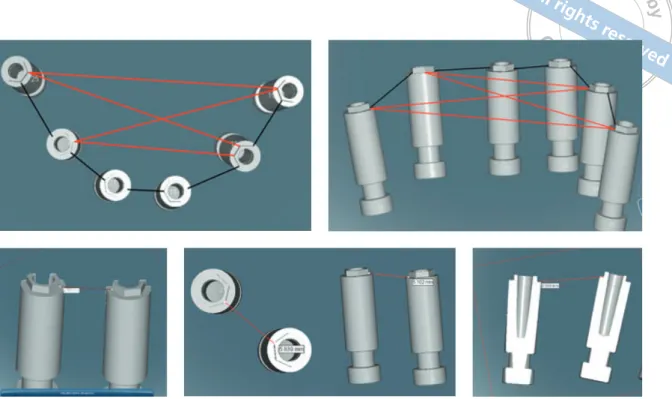
(8) 332 . Pozzi et al. Implant impression techniques. Fig 7 The inter-implant measurements were recorded through a line joining the nearest external hexagon vertices of the adjacent and opposite implants: axial and frontal views.. Fig 8 The interimplant measurements were recorded from the external hexagon vertices measured at the implant platform level of each implant between two easily available and reproducible points under high magnification.. implant replica on the master cast. The distances from the external hexagon vertices (measured at the implant platform level) of each implant to the nearest external hexagon vertices of the adjacent and opposite implants (the I-I distance) were measured and statistically analysed (Fig 7). Each measurement was obtained to the nearest 0.001 mm and was verified from different 3-D perspectives (Fig 8). • The time needed to create impressions, from the screwing of the last impression coping to the removal of the impression, was calculated using a digital clock with a liquid crystal display. • The sulcus bleeding index (SBI) around the implant–abutment interfaces was assessed at the 3-year examination using a plastic periodontal probe (Plast-o-Probe, Dentsply Maillefer, Ballaigues, Switzerland) after removing the prosthesis. The SBI was evaluated at 4 sites around each implant (mesial, distal, buccal and lingual) according to the Mombelli Index (Mombelli & Lang, 1998): the bleeding elicited 20 s after the careful insertion of a periodontal probe 1 mm into the mucosal sulcus, parallel to the abutment wall, was assessed (0 = no bleeding, 1 = spot bleeding, 2 = linear bleeding and 3 = spontaneous bleeding). • The plaque score (PS), defined as the presence of plaque (yes/no) on the abutment–restoration. Eur J Oral Implantol 2013;6(4):325–340. complex, was measured by running a periodontal probe (PCP15, Hu-Friedy, Chicago, IL, USA) parallel to the abutment surfaces, and scored at one site for each implant. The first part of this study assessed the implant casts that had been poured during the fabrication of CAD/CAM complete-arch prostheses according to a randomised crossover study design. Using a computer-generated restricted randomisation list (Random Number Generator Pro 1.91 for Windows, Segobit Software, http://www.segobit.com/), the patients were assigned to receive one of the two types of impression as their first treatment and the other one as their second treatment, 1 week later. The randomised codes designated as ‘plaster’ and ‘VPS’ were enclosed in sequentially numbered, identical, opaque, sealed envelopes. Envelopes were opened sequentially only after the screwing of the last impression coping. The second part of this study was designed as a randomised parallel-group clinical trial. A second computer-generated restricted randomisation list created as previously described was used to allocate the master casts (divided into splinted-VPS and plaster impressions by equal numbers of 19) and was sealed in sequentially numbered, identical, opaque envelopes. An independent consultant prepared all of the envelopes, which were opened immediately after cast fabrication by.
(9) Results A flow diagram of the phases of the trial is shown in Figure 9. A total of 38 edentulous patients requiring a CAD/CAM implant-supported completearch prosthesis (Zirconia or Titanium Implant Bridge, Nobel Biocare) were screened for inclusion in the study. A total of 76 impressions were taken. Two. Clinical comparison according to a parallel-group design 3-Year Follow-Up Enrollment Allocation. a blinded dental technician who was not previously involved in the study. The randomised codes were designated as ‘plaster master’ and ‘plaster control’. The allocation of the casts was blinded during the entire study. The blinded consultant classified and delivered the master casts in such a way that neither the operators (restorative dentists or specialist dental technician) nor the patients were aware of the cast used for the framework fabrication. A descriptive analysis was performed using the mean ± standard deviation (SD) (SPSS for Windows version 18.0; SPSS, Chicago, IL, USA). An a priori independent sample of 55 I-I distances was calculated with G* Power 3.1.3 for Mac OS X (version 10.7.2); effect size f2 = 0.15, error probability _ = 0.05 and power = 0.8 (1 – ß error probability). A mixed model analysis (restricted maximum likelihood, REML) was performed to compare the results of the two interventions with regard to the I-I distances between the cast groups (n = 292). The main effects of implant number and angulation, as well as their distances, were analysed using a univariate analysis of variance (full factorials, univariate general linear model). The I-I distance was the statistical unit. Chair time, results of the VAS score and all the clinical outcomes (MBL, SBI and PS) were compared using an independent-samples t test. The patient was the statistical unit. The potential effect of the type of impression/material on the prosthesis success rate was assessed using the Fisher exact test. The rationale for choosing the Fisher exact test was its appropriateness for small sample sizes of categorical variables. The null hypothesis was that there would be no difference between the interventions with regard to their I-I measurements. All of the statistical comparisons were conducted with a 0.05 level of significance.. Casts comparison according to a cross-over design Allocation Enrollment. Pozzi et al. Fig 9. Implant impression techniques. Patients assessed for eligibility (n = 38). 333. Patients excluded (n = 0). Patients enrolled (n = 38). Plaster impressions (n = 38). Splinted-VPS impressions (n = 38). Test casts group (n = 36) 2 Plaster impressions fractured. Control casts group (n = 38) 2 casts were excluded from the I-I distance comparision due to a loss of the corresponding control resulting in n = 36. Casts poured (n = 74 on 38 patients). Master casts (n = 38) CAD/CAM frameworks (n = 38). Plaster casts group (n = 18). Control casts (n = 36). Splinted-VPS casts group (n = 20). CAD/CAM frameworks (n = 38) Lost to follow-up (n = 0). A flow diagram of the phases of the trial.. plaster impressions showed mobility in the associated copings due to a plaster fracture and they were not eligible to be poured, hence, a total of 74 casts were poured. The patients that experienced plaster impression fractures were excluded from the cast comparison and they received definitive prostheses fabricated onto the splinted-VPS impression. As a consequence, 36 plaster casts and 36 splinted-VPS casts were compared according to the investigated procedures. Furthermore, all 38 patients were clinically treated and the results were analysed in the statistical analyses. One cast per patient was to be randomly allocated as the master cast, however, because of 2 fractured plaster impressions, 2 patients could not have their impressions randomised and the. Eur J Oral Implantol 2013;6(4):325–340.
(10) 334 . Pozzi et al. Implant impression techniques. Fig 10 a) Clinical and b) radiographic outcomes at the 3-year follow-up visit of a CAD/ CAM screw-retained complete prosthesis fabricated onto a master cast derived from a plaster impression. . a. remaining casts were used according to an intentionto-treat analysis. This resulted in an unequal number of plaster (n = 18) and splinted-VPS master casts (n = 20) used to fabricate the definitive prostheses. For each treatment, 4 to 10 external-hex dental implants were placed in the planned anatomic sites (mean 6.2 implants per patient), resulting in a total of 234 dental implants (28 Brånemark System Mk III and 206 NobelSpeedy Groovy, Nobel Biocare). One patient was rehabilitated with 4 axial implants placed in the interforaminal area; 12 patients were rehabilitated according to the original All-on-4 protocol53. The remaining 25 patients were rehabilitated with 5 (n = 3), 6 (n = 9), 8 (n = 8), 9 (n = 1) and 10 (n = 4) implants per arch. A total of 210 axial and 24 angulated implants were placed. The mean (SD) value of tilted implants was 34.8 degrees (±3.94; 95% CI 33.07–36.53 degrees). No patient dropped out and no deviations from the original protocol occurred. No implant was lost, and all of the prostheses were in situ at the time of examination, accounting for a cumulative implant and prosthesis survival rate of 100% 3 years after insertion (Figs 10a and 10b). The main baseline demographic data and intervention characteristics for each group are presented in Tables 1 and 2. All of the CAD/CAM frameworks were clinically accurate and structurally intact. The following complications occurred: 5 chip-off fractures of the porcelain veneer occurred in 5 of the 38 patients. Three chip-off fractures were reported on the prostheses fabricated onto the plaster group casts; the other 2 fractures were reported in the splinted-VPS group casts. No prosthesis replacements were necessary. Two of the 5 fractures were polished intraorally (Dialite, Brasseler USA, Savannah, GA, USA) without. Eur J Oral Implantol 2013;6(4):325–340. b. requiring any additional treatment due to their small size. The remaining 3 fractures affecting the functional areas of the occlusal surfaces were restored with a porcelain laminate. No other complications occurred, either biological (i.e. pain, implant radiolucency or suppuration) or technical/mechanical (i.e. mobility or function). The Fisher exact test revealed no statistically significant difference between the 2 groups for complications (P = 0.331). There were statistically significant differences in the mean VAS scores and chair times (P < 0.05) between the investigated groups, favouring the plaster impression (Table 3). Nevertheless, as gathered from the questionnaire administered at the 3-year follow-up examination, all of the patients were functionally and aesthetically satisfied with their prostheses. Adjacent and opposite inter-implant measurements were performed for each cast according to the total number of implants, resulting in a total of 292 I-I distances per group. Tables 3 and 4 present the summary of the mean values, standard deviations and results of the statistical analyses. The mean difference in the I-I distances between groups was 0.055 ± 0.067 mm (95% CI -0.022 to 0.132 mm; P = 0.931). The results of the univariate analysis of variance indicate that the presence of angulated implants (P = 0.295) produced no significant effect on the deviations for all the measurements. In contrast, the cases with 4 or fewer implants (P = 0.001), as well as a distance between 2 adjacent implants less than 15 mm (P = 0.000), appear to have produced less discrepancy between the casts. Finally, the mean MBL, SBI and PS showed no significant differences (P > 0.05) between the groups (Table 3)..
(11) Pozzi et al. Table 1. 335. Implant impression techniques. Patient and intervention characteristics. Plaster casts group (n = 18). Splinted-VPS casts group (n = 20). Number of patients (implants); n = 38 (234). 18 (111). 20 (123). Number of patients rehabilitated with 4 or less implants (n = 13). 6 (33.3%). 7 (28.6%). Number of patients rehabilitated with 5 or more implants (n = 25). 12 (66.6%). 13 (71.4%). Patients/implants placed in the maxilla (n = 130). 8/55 (49.5%). 11/75 (60.9%). Patients/implants placed in the mandible (n = 104). 10/56 (51.5%). 9/48 (39.1%). Males (n = 18). 10 (55.5%). 8 (40.0%). Females (n = 20). 8 (54.5%). 12 (60.0%). Mean age (range) at the time of intervention. 67.7 (50–83) ± 8.8. 69.3 (45–81) ± 8.5. Number of CAD/CAM zirconia/titanium implant prostheses (n = 26/12). 12/6. 14/6. Number of patients (implants) treated with computer-guided surgery (n = 28). 12 (87). 16 (109). Number of patients (implants) treated with conventional surgery (n = 10). 6 (24). 4 (14). Number of angulated implants (n = 24). 12 (10.8%). 12 (9.8%). Mean implant angulation (total average 34.8 degrees). 35.15 ± 3.79. 34.56 ± 4.19. Number of axial implants (n = 210). 99 (89.2%). 111 (90.2%). Table 2. Main characteristics of the materials used. Times are expressed in seconds. Splint-VPS (n = 38). Plaster (n = 38). Working time. 90. 30. Setting time. 180. 180–300. Average polymerisation time (Primopattern LG gel). 480. –. Setting expansion. 0.05–0.3%. 0.01–0.12%. Table 3. Mean measurements of distances, chair time, VAS, MBL, SBI and PS.. Outcomes. Test casts group (n1 = 292). Control casts group (n1 = 292). Mean difference. P value. I-I distance. 15.620 ± 7.851 mm (95% CI: 14.716–16.525 mm). 15.564 ± 7.830 mm (95% CI: 14.662–16.466 mm). 0.055 ± 0.067 mm (95% CI: -0.022–0.132 mm). 0.931*. Test casts group (n2 = 38). Control casts group (n2 = 38). Mean difference. Chair time. 502.63 ± 69.84 s (95% CI: 480.43–524.83 mm). 869.16 ± 139.51 s (95% CI: 824.90–913.42 mm). 366.53 ± 82.45 s (95% CI: 340.32–392.74 mm). 0.000#. VAS§. 92.73 ± 6.46% (95% CI: 90.70–94.86 mm). 61.18 ± 15.21% (95% CI: 56.34–66.02 mm). 31.60 ± 16.96% (95% CI: 26.15–37.05 mm). 0.000#. Plaster (n3 = 18). Splinted-VPS (n3 = 20). Mean difference. MBL. 0.86 ± 0.18 mm (95% CI: 0.77–0.94 mm). 0.90 ± 0.16 mm (95% CI: 0.83–0.97 mm). 0.034 ± 0.56 mm (95% CI: -0.15–0.80 mm). 0.552#. SBI. 5.39 ± 3.91% (95% CI: 3.59–7.19 mm). 5.55 ± 5.19% (95% CI: 3.28–7.82 mm). 0.16 ± 1.50% (95% CI: -3.06–3.56 mm). 0.915#. PS. 10.00 ± 3.40% (95% CI: 8.43–11.57 mm). 9.85 ± 4.57% (95% CI: 7.85–11.85 mm). 1.15 ± 1.31% (95% CI: -2.52–2.82 mm). 0.910#. n1: number of measurements n2: number of procedures n3: number of patients §Overall patient satisfaction immediately after the impressions *Mixed model analysis #Independent sample t test. Eur J Oral Implantol 2013;6(4):325–340.
(12) 336 . Pozzi et al. Table 4. Implant impression techniques. Mixed model analysis between groups.. Groups. Variabilities. VPS. Angulated implants. Sample size. Mean ± SD (mm). Mean difference ± SD (mm). 60. 15.309 ± 5.802. 0.040 ± 0.064 (95% CI: 0.023–0.057 mm). Plaster VPS. 15.349 ± 5.804 Straight implants. 232. Plaster VPS. 15.690 ± 8.308 ≤4 implants. 64. Plaster VPS. Plaster VPS Plaster. 15.978 ± 5.719 16.013 ± 5.733. >4 implants. 228. Plaster VPS. 15.630 ± 8.283. 15.448 ± 8.334 15.511 ± 8.357. ≤15 mm (distance between implants). 177. >15 mm (distance between implants). 115. 10.774 ± 2.871 10.813 ± 2.884 22.937 ± 7.300 23.020 ± 7.300. Discussion The long-term success of implant-retained prostheses and the incidence of biological and biomechanical complications may also depend on the precision of the prosthetic superstructure’s fit13,29. It has been stated that non-passively fitting implant frameworks may cause the failure of the prosthetic components or of the entire prosthesis8,10,54,55. Bone loss has been attributed to a lack of passive fit, which may result in unequal stresses and force distributions in the periimplant zone, leading to bone resorption8. The passive fit of the cast alloy screw-retained implant prosthesis is related to the accuracy of the conventional lost wax and casting procedures, however, it is most directly dependent on the accuracy of the impression and master cast pouring techniques8,19,28. Nevertheless, an absolutely passive fit is difficult to obtain because of the required processing and manufacturing laboratory phases22,56. It has been demonstrated that CAD/CAM technology and computer numeric controlled milling equipment provide a significantly improved fit compared to conventional manufacturing57. These newer techniques overcome the drawbacks of the metal alloy complete-arch framework casting procedure, which is intrinsically limited by its high-skill nature and the potential lack of fitting and accuracy25,58-59. The clinical relevance of introducing the CAD/CAM workflow to daily practice is related to the need for predictable, passively fitting superstructures to minimise additional stress at the interfaces. Eur J Oral Implantol 2013;6(4):325–340. 0.059 ± 0.067 (95% CI: 0.051–0.065 mm). F-ratio. P value. 1.099. 0.295. 11.152. 0.001. 19.426. 0.000. 0.030 ± 0.058 (95% CI: 0.054–0.071 mm) 0.062 ± 0.068 (95% CI: 0.014–0.047 mm) 0.039 ± 0.057 (95% CI: 0.029–0.048 mm) 0.081 ± 0.074 (95% CI: 0.069–0.092 mm). of the implant-abutment-bone complex27. Studies on implant impression accuracy have repeatedly shown that the resulting master casts fail to replicate the exact intraoral situation60,61. Nevertheless, the appropriate techniques for the precise transfer of clinical data to the laboratory remain the topic of scientific investigations and academic controversies. Several studies have evaluated the accuracy of implant impressions by comparing the inter-implant distance of the working cast to that of a reference control cast27,31,39,42,52,62. The main aim of the present study was to compare two different impression techniques for implants in totally edentulous patients in terms of discrepancy between them, chair time required and to investigate the patients’ perception of the treatments, and clinical outcomes. After placement, CAD/CAM screw-retained complete-arch zirconia and titanium prostheses were followed up for 3 years to assess the clinical and radiological outcomes of 38 patients with completely edentulous treated jaws. An optical scanning technique was used to assess the in vitro inter-implant discrepancy between the casts40,63,64. The framework fit was tested in vivo by applying the SO-ST in the mouth, an efficient means of clinically evaluating this parameter8,10,27,42. The main limitation of the current trial was the limited sample size. A minor limitation was the use of two different CAD/CAM framework materials. However, the literature indicates that zirconia and titanium produce similar outcomes in terms of fit and strain development and that the magnitude of.
(13) Pozzi et al. peri-implant strain is primarily affected by the fit of the framework rather than the material31,55. Furthermore, the present research assessed the in vivo accuracy of the tested implant impression procedures in daily practice, in terms of the clinical success of the delivered prostheses, which were followed up for 3 years. The null hypothesis that there would be no difference in the inter-implant discrepancy between the casts produced by the tested implant impression techniques was accepted. The observed mean difference of 55 μm resulted in an acceptable clinical fit with screw-retained implant prostheses, in accordance with a similar previous study40. Furthermore, this study included 3 categorical variables (implant angulation, implant number and implant distance) with at least 60 measurements each. This sample size indicated a significant effect of implant number, with a larger difference associated with master casts with more than 4 implants. There was also a significant effect of implant distance, with better results for I-I spans of less than 15 mm. In contrast, the presence of angulated implants appears to have produced no significant effect on the master cast accuracy. As expected, the mean I-I distance of the plaster impressions was slightly higher than that of the splinted-VPS in all measurements due to the slight volumetric expansion of the plaster, unlike the shrinkage of the VPS and acrylic material. However, the magnitude of the difference ranged from 29 to 79 μm. Because the clinical and radiographic measurements revealed no differences between interventions, according to Papaspyridakos et al27, these results may be considered within the maximum tolerance to indicate an acceptable clinical fit of the screw-retained complete-arch prosthesis. Implant splinting might be a determining factor for achieving an accurate master cast, regardless of the impression material8,10,27,42. The splinting technique eliminates any rotational or translational movements of the impression copings during the impression and analogue attachment procedures39. However, resin shrinkage and manipulation remain a concern65. In a systematic review, Lee et al9 reported that some studies found no difference or better results with the non-splinted technique. Nevertheless, most of the aforementioned studies were published more than 10 years ago and investigated only metal cast. Implant impression techniques. alloy frameworks that were sectioned and reconnected/soldered intraorally to achieve an acceptable clinical fit. Furthermore, the accuracy of 2-D linear measurements of an object may be less precise compared with the 3-D measurements. Nevertheless, more recent literature has reported a higher accuracy of the splinted technique27,39,42,60,62. Independent of the intrinsic features of the impression materials, the underlying principle was the connection of all the impression copings using a rigid material to prevent any possible individual coping movements during impression making and master cast pouring. Although low-shrinkage acrylic resin is the most commonly used splinting material, its volumetric contraction related to the setting phase ranged between 6.5 and 7.9% in the first 24 h, with up to 80% of the shrinkage occurring during the first 17 min after mixing37,66. To minimise the loss of accuracy related to the intraoral shrinkage of the acrylic resin, some authors have suggested taking a preliminary unsplinted impression to connect the impression copings onto the cast using a lowshrinkage resin framework. Therefore, after waiting for the complete polymerisation of the resin, the resin framework was sectioned onto the model using a 0.2 mm carborundum disk to obtain single interimplant connectors, which were successively related together into the mouth with a minimal amount of the same resin. Assif et al7 assessed the efficacy of impression plaster as a splinting material. Impression plaster is quite accurate and rigid, does not bend or distort, and sets rapidly. This material is easy to manipulate, less time consuming and less expensive to use, and the exothermic reaction during the setting time is negligible. Moreover, Nissan et al67 and Eid68 described how to use the plaster to create an implant impression and reported its accuracy, ease of manipulation and decreased working time. Impression plaster (ANSI-ADA 2000) is based on calcined calcium sulfate hemihydrate, which reacts with water to form a hard mass of calcium sulfate dihydrate with a lower setting expansion (0.01–0.12%) compared with the low shrinkage rate of the flowable light-curing acrylic resin (0.05–0.3%)69. The plaster impression allows for a good reproduction of surface details and excellent dimensional stability. However, some problems (i.e. fractures) may occur in the. Eur J Oral Implantol 2013;6(4):325–340. 337.
(14) 338 . Pozzi et al. Implant impression techniques. presence of deep anatomic undercuts or angulated implants. In the present study, a disassembled custom tray was used to assist the clinician in overcoming the bone undercuts. Although the 2 excluded patients presented fractures in the plaster and mobility of the related impression copings, the trays were removed from their mouths with no discomfort. All of these patients presented angulated implants with an angulation of more than 40 degrees from the axial implant of the same side. To reduce the risk of plaster fracture, a proper design of the custom tray is mandatory to allow a larger thickness of the impression material around the angulated implants. However, according to Sorrentino et al16, in situations in which there are one or more angulated implants (≥35 degrees between axial and angulated implants), a slightly less precise impression could be created due to the greater forces required for impression removal and the related potential distortion or fracture of the VPS or plaster, respectively. Because of its more favourable, lower modulus of elasticity, silicone material could be considered as a viable alternative that enables the easy removal of the impression and reduces the permanent deformations caused by the stress between the impression material and the copings70. In addition, the design of copings with a shortened connection length must be considered a relevant factor to ease the removal of the copings from the internal/external connection of the implants, avoiding a deep engagement of the component71. In the present study, the flatto-flat implant–abutment interface with 0.7 mm high external hexagonal connection did not produce any difficulties in removing the plaster impression, considering the mean angulation of the investigated angulated implants of 34.8 degrees (ranging from 35 to 45 degrees). Nevertheless, the parallel positioning of the implants is not always clinically achievable due to possible anatomical limitations. For the latter, although the implant-level impression method could better transfer the implant position72, the abutmentlevel impression by means of angulated abutments could be considered in the presence of angulated implants with an angulation of more than 40 degrees. From a clinical perspective, the present study supports the hypothesis that if plaster is used as an impression material, splinting the implants in accordance with the aforementioned good practice techniques is no longer a prerequisite for the success of CAD/CAM. Eur J Oral Implantol 2013;6(4):325–340. screw-retained implant-supported complete-arch prostheses. The plaster enables the recording of the 3-D implant position and the rigid connection of the implant copings with a lack of accuracy that is not relevant from the clinical perspective. Furthermore, the plaster impression may eliminate the need for the pre-scan try-in of the resin frameworks without affecting the success of the implant/prosthetic, as well as the sectioning and soldering in situations of metal prosthetic superstructures to overcome the potential lack of passive fit. The chair time required for the two impression procedures and the high patient confidence level for plaster impressions were significantly different, with a shorter duration and greater patient confidence associated with plaster impressions. Although only CAD/CAM frameworks were tested, the present research allows some preliminary and generalisable conclusions. Particularly, plaster impressions combined with CAD/CAM technology can provide highly accurate and successful screw-retained complete-arch implant prostheses. The choice between splinted-VPS and plaster essentially depends on several variables, such as the number of intraoral undercuts, the angulation of the implants (if angulated abutments were not used) and the experience of the clinician. The clinicians involved in this study were highly experienced in the rehabilitation of totally edentulous patients with axial and angulated implants. This factor may limit the extrapolation of the present results; however, all of the procedures were tested in real clinical conditions, and they can be generalised with confidence to a wider population with similar characteristics.. Conclusions Within the limitations of this study, it was shown that the clinical outcome of plaster implant impressions for completely edentulous patients is the same as that of splinted-VPS impressions. All of the CAD/ CAM prostheses were associated with a similar level of success during the entire follow-up period. The intraoral pre-scan try-in of the resin framework can be avoided with both types of impressions. Nevertheless, plaster impressions may be less time consuming and more comfortable for the patient, but can sometimes fracture and need to be taken again..
(15) Pozzi et al. Acknowledgements The authors would like to thank Dr Franco Biondi (Clinical Expert, Nobel Biocare) for his research advice and Mr Alberto Bonaca, Mr Paolo Paglia and Mr Bruno Scarfò for their contributions.. References 1. Adell R, Lekholm U, Rockler B, Branemark PI. A 15-year study of osseointegrated implants in the treatment of the edentulous jaw. Int J Oral Surg 1981;10:387-416. 2. Branemark PI. Osseointegration and its experimental background. J Prosthet Dent 1983;50:399-410. 3. Schwarz MS. Mechanical complications of dental implants. Clin Oral Implants Res 2000;11(Suppl 1):156-158. 4. Karl M, Winter W, Taylor TD, Heckmann SM. In vitro study on passive fit in implant-supported 5-unit fixed partial dentures. Int J Oral Maxillofac Implants 2004;19:30-37. 5. Assif D, Fenton A, Zarb G, Schmitt A. Comparative accuracy of implant impression procedures. Int J Periodontics Restorative Dent 1992;12:112-121. 6. Assif D, Marshak B, Schmidt A. Accuracy of implant impression techniques. Int J Oral Maxillofac Implants 1996;11:216-222. 7. Assif D, Nissan J, Varsano I, Singer A. Accuracy of implant impression splinted techniques: effect of splinting material. Int J Oral Maxillofac Implants 1999;14:885-888. 8. Jemt T, Book K. Prosthesis misfit and marginal bone loss in edentulous implant patients. Int J Oral Maxillofac Implants 1996;11:620-625. 9. Lee H, So JS, Hochstedler JL, Ercoli C. The accuracy of implant impressions: a systematic review. J Prosthet Dent 2008;100: 285-291. 10. Abduo J, Lyons K, Bennani V, Waddell N, Swain M. Fit of screw-retained fixed implant frameworks fabricated by different methods: a systematic review. Int J Prosthodont 2011; 24:207-220. 11. Del’Acqua MA, Arioli-Filho JN, Compagnoni MA, Mollo F de AJ. Accuracy of impression and pouring techniques for an implant-supported prosthesis. Int J Oral Maxillofac Implants 2008;23:226-236. 12. Romero GG, Engelmeier R, Powers JM, Canterbury AA. Accuracy of three corrective techniques for implant bar fabrication. J Prosthet Dent 2000;84:602-607. 13. Takahashi T, Gunne J. Fit of implant frameworks: an in vitro comparison between two fabrication techniques. J Prosthet Dent 2003;89:256-260. 14. Sartori IA de M, Ribeiro RF, Francischone CE, de Mattos MDGC. In vitro comparative analysis of the fit of gold alloy or commercially pure titanium implant-supported prostheses before and after electroerosion. J Prosthet Dent 2004;92: 132-138. 15. Wegner K, Weskott K, Zenginel M, Rehmann P, Wöstmann B. Effects of Implant System, Impression Technique, and Impression Material on Accuracy of the Working Cast. Int J Oral Maxillofac Implants 2013;28:989-995. 16. Sorrentino R, Gherlone EF, Calesini G, Zarone F. Effect of implant angulation, connection length, and impression material on the dimensional accuracy of implant impressions: an in vitro comparative study. Clin Implant Dent Relat Res 2010;12(Suppl 1):e63-e76. 17. Sahin S, Cehreli MC. The significance of passive framework fit in implant prosthodontics: current status. Implant Dent 2001;10:85-92.. Implant impression techniques. 18. Mitrani R, Vasilic M, Bruguera A. Fabrication of an implantsupported reconstruction utilizing CAD/CAM technology. Pract Proced Aesthet Dent 2005;17:71-78;quiz 80. 19. Al-Fadda SA, Zarb GA, Finer Y. A comparison of the accuracy of fit of 2 methods for fabricating implant-prosthodontic frameworks. Int J Prosthodont 2007;20:125-131. 20. Karl M, Taylor TD. Effect of material selection on the passivity of fit of implant-supported restorations created with computer-aided design/computer-assisted manufacture. Int J Oral Maxillofac Implants 2011;26:739-745. 21. Karl M, Graef F, Wichmann M, Krafft T. Passivity of fit of CAD/CAM and copy-milled frameworks, veneered frameworks, and anatomically contoured, zirconia ceramic, implant-supported fixed prostheses. J Prosthet Dent 2012; 107:232-238. 22. Kapos T, Ashy LM, Gallucci GO, Weber H-P, Wismeijer D. Computer-aided design and computer-assisted manufacturing in prosthetic implant dentistry. Int J Oral Maxillofac Implants 2009;24(Suppl):110-117. 23. Larsson C, Vult von Steyern P, Nilner K. A prospective study of implant-supported full-arch yttria-stabilized tetragonal zirconia polycrystal mandibular fixed dental prostheses: three-year results. Int J Prosthodont 2010;23:364-369. 24. Komiyama A, Klinge B, Hultin M. Treatment outcome of immediately loaded implants installed in edentulous jaws following computer-assisted virtual treatment planning and flapless surgery. Clin Oral Implants Res 2008;19:677-685. 25. Ortorp A, Jemt T. CNC-milled titanium frameworks supported by implants in the edentulous jaw: a 10-year comparative clinical study. Clin Implant Dent Relat Res 2012;14:88-99. 26. Sanna AM, Molly L, van Steenberghe D. Immediately loaded CAD-CAM manufactured fixed complete dentures using flapless implant placement procedures: a cohort study of consecutive patients. J Prosthet Dent 2007;1997:331-339. 27. Papaspyridakos P, Lal K. Computer-assisted design/ computer-assisted manufacturing zirconia implant fixed complete prostheses: clinical results and technical complications up to 4 years of function. Clin Oral Implants Res 2013;24: 659-665. 28. Carr AB, Stewart RB. Full-arch implant framework casting accuracy: preliminary in vitro observation for in vivo testing. J Prosthodont 1993;2:2-8. 29. Taylor TD. Prosthodontic problems and limitations associated with osseointegration. J Prosthet Dent 1998;79:74-78. 30. Balmer S, Mericske-Stern R. [Implant-supported bridges in the edentulous jaw. Clinical aspects of a simple treatment concept]. Schweiz Monatsschr Zahnmed 2006;116: 728-739. 31. Abduo J, Bennani V, Waddell N, Lyons K, Swain M. Assessing the fit of implant fixed prostheses: a critical review. Int J Oral Maxillofac Implants 2010;25:506-515. 32. Gordon GE, Johnson GH, Drennon DG. The effect of tray selection on the accuracy of elastomeric impression materials. J Prosthet Dent 1990;63:12-15. 33. Carr AB. Comparison of impression techniques for a fiveimplant mandibular model. Int J Oral Maxillofac Implants 1991;6:448-455. 34. Barrett MG, de Rijk WG, Burgess JO. The accuracy of six impression techniques for osseointegrated implants. J Prosthodont 1993;2:75-82. 35. Rueda LJ, Sy-Munoz JT, Naylor WP, Goodacre CJ, Swartz ML. The effect of using custom or stock trays on the accuracy of gypsum casts. Int J Prosthodont 1996;9:367-373. 36. Burns J, Palmer R, Howe L, Wilson R. Accuracy of open tray implant impressions: an in vitro comparison of stock versus custom trays. J Prosthet Dent 2003;89:250-255. 37. Mojon P, Oberholzer JP, Meyer JM, Belser UC. Polymerization shrinkage of index and pattern acrylic resins. J Prosthet Dent 1990;64:684-688.. Eur J Oral Implantol 2013;6(4):325–340. 339.
(16) 340 . Pozzi et al. Implant impression techniques. 38. Lee SJ, Cho S-B. Accuracy of five implant impression technique: effect of splinting materials and methods. J Adv Prosthodont 2011;3:177-185. 39. Vigolo P, Fonzi F, Majzoub Z, Cordioli G. An evaluation of impression techniques for multiple internal connection implant prostheses. J Prosthet Dent 2004;92:470-476. 40. Papaspyridakos P, Benic GI, Hogsett VL, White GS, Lal K, Gallucci GO. Accuracy of implant casts generated with splinted and non-splinted impression techniques for edentulous patients: an optical scanning study. Clin Oral Implants Res 2012;23:676-681. 41. Assuncao WG, Britto RC, Ricardo Barao VA, Delben JA, Santos dos PH. Evaluation of impression accuracy for implant at various angulations. Implant Dent 2010;19:167-174. 42. Papaspyridakos P, Lal K, White GS, Weber H-P, Gallucci GO. Effect of splinted and nonsplinted impression techniques on the accuracy of fit of fixed implant prostheses in edentulous patients: a comparative study. Int J Oral Maxillofac Implants 2011;26:1267-1272. 43. Schulz KF, Altman DG, Moher D. CONSORT 2010 Statement: updated guidelines for reporting parallel group randomised trials. BMJ 2010;340:c332. 44. Keats AS. The ASA classification of physical status--a recapitulation. Anesthesiology 1978;49:233-236. 45. Tallarico M, Vaccarella A, Marzi GC, Alviani A, Campana V. A prospective case-control clinical trial comparing 1and 2-stage Nobel Biocare TiUnite implants: resonance frequency analysis assessed by Osstell Mentor during integration. Quintessence Int 2011;42:635-644. 46. Jemt T. Failures and complications in 391 consecutively inserted fixed prostheses supported by Branemark implants in edentulous jaws: a study of treatment from the time of prosthesis placement to the first annual checkup. Int J Oral Maxillofac Implants 1991;6:270-276. 47. Tan KB, Rubenstein JE, Nicholls JI, Yuodelis RA. Threedimensional analysis of the casting accuracy of one-piece, osseointegrated implant-retained prostheses. Int J Prosthodont 1993;6:346-363. 48. Eisenmann E, Mokabberi A, Walter MH, Freesmeyer WB. Improving the fit of implant-supported superstructures using the spark erosion technique. Int J Oral Maxillofac Implants 2004;19:810-818. 49. Chang T-L, Maruyama C, White SN, Son S, Caputo AA. Dimensional accuracy analysis of implant framework castings from 2 casting systems. Int J Oral Maxillofac Implants 2005;20:720-725. 50. Pozzi A, Holst S, Fabbri G, Tallarico M. Clinical reliability of CAD/CAM cross-arch zirconia bridges on immediately loaded implants placed with computer-assisted/template-guided surgery: a retrospective study with a follow-up between 3 and 5 years. Clin Implant Dent Relat Res 2013 Aug 5. [Epub ahead of print] 51. Naylor CK. Fabrication of a custom anterior guide table. J Prosthet Dent 1979;42:466-469. 52. Holst S, Persson A, Wichmann M, Karl M. Digitizing implant position locators on master casts: comparison of a noncontact scanner and a contact-probe scanner. Int J Oral Maxillofac Implants 2012;27:29-35. 53. Malò P, Rangert B, Nobre M. “All-on-Four” immediatefunction concept with Brånemark System implants for completely edentulous mandibles: a retrospective clinical study. Clin Implant Dent Relat Res 2003;5(Suppl 1):2-9. 54. Papaspyridakos P, Chen C-J, Chuang S-K, Weber H-P, Gallucci GO. A systematic review of biologic and technical complications with fixed implant rehabilitations for edentulous patients. Int J Oral Maxillofac Implants 2012;27:102-110.. Eur J Oral Implantol 2013;6(4):325–340. 55. Abduo J, Lyons K. Clinical considerations for increasing occlusal vertical dimension: a review. Aust Dent J 2012 28;57:2-10. 56. Winter W, Mohrle S, Holst S, Karl M. Bone loading caused by different types of misfits of implant-supported fixed dental prostheses: a three-dimensional finite element analysis based on experimental results. Int J Oral Maxillofac Implants 2010;25:947-952. 57. Katsoulis J, Mericske-Stern R, Rotkina L, Zbären C, Enkling N, Blatz MB. Precision of fit of implant-supported screw-retained 10-unit computer-aided-designed and computer-aided-manufactured frameworks made from zirconium dioxide and titanium: an in vitro study. Clin Oral Implants Res 2012 Oct 2. [Epub ahead of print] 58. Jemt T, Back T, Petersson A. Precision of CNC-milled titanium frameworks for implant treatment in the edentulous jaw. Int J Prosthodont 1999;12:209-215. 59. Karl M, Wichmann MG, Heckmann SM, Krafft T. Strain development in 3-unit implant-supported CAD/CAM restorations. Int J Oral Maxillofac Implants 2008;23:648-652. 60. Hariharan R, Shankar C, Rajan M, Baig MR, Azhagarasan NS. Evaluation of accuracy of multiple dental implant impressions using various splinting materials. Int J Oral Maxillofac Implants 2010;25:38-44. 61. Ortorp A, Jemt T, Back T. Photogrammetry and conventional impressions for recording implant positions: a comparative laboratory study. Clin Implant Dent Relat Res 2005;7:43-50. 62. Chang W-G, Vahidi F, Bae K-H, Lim B-S. Accuracy of three implant impression techniques with different impression materials and stones. Int J Prosthodont 2012;25:44-47. 63. Stimmelmayr M, Guth J-F, Erdelt K, Happe A, Schlee M, Beuer F. Clinical study evaluating the discrepancy of two different impression techniques of four implants in an edentulous jaw. Clin Oral Investig 2013;17:1929-1935. 64. Del Corso M, Aba G, Vazquez L, Dargaud J, Dohan Ehrenfest DM. Optical three-dimensional scanning acquisition of the position of osseointegrated implants: an in vitro study to determine method accuracy and operational feasibility. Clin Implant Dent Relat Res 2009;11:214-221. 65. Burawi G, Houston F, Byrne D, Claffey N. A comparison of the dimensional accuracy of the splinted and unsplinted impression techniques for the Bone-Lock implant system. J Prosthet Dent 1997;77:68-75. 66. Baroudi K, Saleh AM, Silikas N, Watts DC. Shrinkage behaviour of flowable resin-composites related to conversion and filler-fraction. J Dent 2007;35:651-655. 67. Nissan J, Barnea E, Krauze E, Assif D. Impression technique for partially edentulous patients. J Prosthet Dent 2002;88:103-104. 68. Eid N. An implant impression technique using a plaster splinting index combined with a silicone impression. J Prosthet Dent 2004;92:575-577. 69. Boaro LCCC, Gonçalves F, Guimarães TC, Ferracane JL, Versluis A, Braga RR. Polymerization stress, shrinkage and elastic modulus of current low-shrinkage restorative composites. Dent Mater 2010;26:1144-1150. 70. Mpikos P, Tortopidis D, Galanis C, Kaisarlis G, Koidis P. The effect of impression technique and implant angulation on the impression accuracy of external- and internal-connection implants. Int J Oral Maxillofac Implants 2012;27:1422-1428. 71. Vigolo P, Majzoub Z, Cordioli G. Evaluation of the accuracy of three techniques used for multiple implant abutment impressions. J Prosthet Dent 2003;89:186-192. 72. Alikhasi M, Siadat H, Monzavi A, Momen-Heravi F. Threedimensional accuracy of implant and abutment level impression techniques: effect on marginal discrepancy. J Oral Implantol 2011;37:649-657..
(17)
Figura


+5


Documenti correlati
The overall aim of this thesis is to examine the relationship among VO2p kinetics (reflecting muscle O2 consumption), bulk O2 delivery (as measured by conduit artery limb
In general terms, determining the field capacity soil mois- ture by the traditionally-proposed technique of a prefixed point of the water retention function results in
La più completa classificazione delle problematiche relative alla progettazione architettonica assistita da computer di quegli anni si deve forse a William Mitchell che
This new RT FL-DNA method was compared not only with positive iFOBT values, but also with negative values of the diagnostic iFOBT so as to evaluate if a multiple approach
Summary: Maturity is one of the most important biological parameters used in stock assessment programmes. Indeed, the macroscopic stage of gonadal development is an essential
Come l’autoconsegna dolorosa del Figlio ha trasformato la sofferenza in amore, così la storia delle sofferenze del mondo può essere trasformata in comunione con
One of the most recent innovations in bone augmentation surgery is represented by computer-aided-design/computer-aided-manufacturing (CAD/CAM) customized titanium meshes, which can
The model will be used in subsequent studies for head loss and velocity measurements, to relate surface roughness characteristics to hydraulic resistance, to investigate the near
