Università Politecnica delle Marche
Corso di Dottorato di Ricerca in Ingegneria Civile, Ambientale, Edile e Architettura Curriculum in Ingegneria Civile, Ambientale, Edile e Architettura
---
External Dissipative Rocking System
Ph.D. Dissertation of:
Laura Gioiella
Advisor:Prof. Fabrizio Gara
Co-Advisor:
Alessandro Balducci
Curriculum Supervisor:
Prof. Stefano Lenci
Università Politecnica delle Marche
Dipartimento di Ingegneria, Civile, Edile e Architettura
Acknowledgments
I wish to thank Professor Andrea Dall'Asta and PhD Enrico Tubaldi for their time and patience and for the great opportunity to work with them during these years.
I am thankful to Professor Fabrizio Gara for his support during all my PhD activity. I would like to thank Professor Luigino Dezi and Alessandro Balducci for giving me the chance to accomplish this PhD course.
Finally, I would like to thank all the staff of the Department I.C.E.A for supporting me through these years.
Contents
Contents ______________________________________________________________ i List of Figures _________________________________________________________ v List of Tables ________________________________________________________ xi Abstract _______________________________________________________________ 1 Sommario _____________________________________________________________ 3 Introduction ____________________________________________________________ 5 Chapter 1______________________________________________________________ 9Seismic Passive Control Systems ___________________________________________ 9 1.1 Seismic isolation ________________________________________________ 12 1.2 Passive supplemental dampers______________________________________ 14 1.2.1 Hysteretic Dampers __________________________________________ 14 1.2.2 Viscous and Visco-elastic Dampers _____________________________ 15 1.2.3 Recentering systems _________________________________________ 17 1.3 Supplemental damping: structural configurations _______________________ 19
Chapter 2_____________________________________________________________ 27
Dissipative rocking system: problem formulation _____________________________ 27 2.1 Equation of motion ______________________________________________ 32 2.2 Generalized SDOF system approximation _____________________________ 35 2.3 Time domain analysis ____________________________________________ 36 2.3.1 State space formulation _______________________________________ 36 2.3.2 Free vibrations and modal properties ____________________________ 37 2.3.3 Seismic response via modal decomposition method _________________ 38
2.3.4 Modal properties of a SDOF system ____________________________ 39 2.4 Frequency domain analysis ________________________________________ 42 2.4.1 Fourier transform of the problem _______________________________ 43 2.5 The Chu et al. formulation ________________________________________ 44
Chapter 3 ____________________________________________________________ 49
Case studies __________________________________________________________ 49 3.1 Van Nuys building ______________________________________________ 49 3.1.1 Description ________________________________________________ 50 3.1.2 Recorded earthquakes and related damages _______________________ 52 3.1.3 Seismic hazard _____________________________________________ 54 3.1.4 Modelling criteria ___________________________________________ 55 3.1.5 Retrofit configurations _______________________________________ 56 3.2 Camerino building ______________________________________________ 58 3.2.1 Description ________________________________________________ 58 3.2.2 Seismic hazard _____________________________________________ 59 3.2.3 Modelling criteria ___________________________________________ 60 3.2.4 Retrofit configurations _______________________________________ 60 Chapter 4 ____________________________________________________________ 61 Modal Properties ______________________________________________________ 61 4.1 Van Nuys building ______________________________________________ 62 4.1.1 Modal properties of the undamped system ________________________ 62 4.1.2 Modal properties of the damped system __________________________ 65 4.2 Camerino building ______________________________________________ 69 4.2.1 Modal properties of the undamped system ________________________ 69 4.2.2 Modal properties of the damped system __________________________ 72
Chapter 5 ____________________________________________________________ 75
Seismic response ______________________________________________________ 75 5.1 Van Nuys building ______________________________________________ 76 5.2 Camerino building ______________________________________________ 87
Chapter 6 ____________________________________________________________ 97
Frequency Domain Analysis _____________________________________________ 97 6.1 A stationary stochastic representation of the input ______________________ 97 6.1.1 Analysis of the Van Nuys building subjected to random excitations ___ 100
Chapter 7 ___________________________________________________________ 105
Open Problems _______________________________________________________ 105 7.1 Non-linear viscous dampers ______________________________________ 106
7.1.1 Equivalence of dissipated energy ______________________________ 107 7.1.2 Comparison between linear and non-linear fluid viscous dampers _____ 108 7.2 Comparison with other retrofitting schemes __________________________ 121 7.2.1 Equation of motion of a finite stiffness MPD system _______________ 122 7.2.2 Seismic response of a MPD system ____________________________ 122 7.2.3 Systems comparison: MPD and dissipative rocking bracing _________ 127 7.3 Soil Structure Interaction (SSI) ____________________________________ 133 7.3.1 Lumped parameter model for time-domain analysis ________________ 135 7.3.2 Soil and foundations characteristics ____________________________ 136 7.3.3 Preliminary results _________________________________________ 137
Conclusion __________________________________________________________ 141 References ___________________________________________________________ 143
Appendix A __________________________________________________________ 149 Case studies FEM models _______________________________________________ 149
List of Figures
Figure 1-1 Performance Based Design matrix __________________________________ 10 Figure 1-2 Cost components comparison among offices, hotels and hospitals proposed by
Taghavi and Miranda 2003 ______________________________________ 11 Figure 1-3 Seismic protection techniques: (a) Capacity Design, (b) Supplemental Dampers,
(c) Seismic Isolation ___________________________________________ 12 Figure 1-4 Lengthening of the fundamental period due to seismic isolation ___________ 13 Figure 1-5 Elastomeric bearing: (a) scheme, (b) force-shear deformation hysteretic loop 13 Figure 1-6 FPS: (a) double surface scheme, (b) force-displacement loop _____________ 14 Figure 1-7 Hysteretic dampers cycles: (a) friction, (b) elasto-plastic, (c) elasto-plastic
hardening ___________________________________________________ 15 Figure 1-8 Effects of visco-elastic devices on the period of a structure _______________ 15 Figure 1-9 Visco-elastic damper acting in shear (a), force-displacement cycle (b) ______ 16 Figure 1-10 FVD scheme (a), force-velocity curves for linear and non-linear FVDs (b) _ 17 Figure 1-11 Force-displacement loops for linear and non-linear FVDs ______________ 17 Figure 1-12 Flag-Shaped hysteresis loop ______________________________________ 18 Figure 1-13 EDR device proposed by Nims et al. 1993 ___________________________ 18 Figure 1-14 SCED system proposed by Christopoulos et al. (2008) _________________ 18 Figure 1-15 Scheme of an undamped SDOF (primary structure) connected to a TMD ___ 19 Figure 1-16 VD Walls proposed by Arima et al. 1988 ____________________________ 20 Figure 1-17 FVD traditional installations within the frames (a) chevron braces, (b)
diagonal braces _______________________________________________ 21 Figure 1-18 External alternative FVDs configurations: (a) inserted into a ventilated
facade, (b) installed within planar bracing connected to the building _____ 21 Figure 1-19 Coupling with an external stiff contrasting structure ___________________ 22 Figure 1-20 Coupling with an external shear deformable bracing structure ___________ 22 Figure 1-21 FVDs coupling adjacent shear walls (a) wall dissipative bracings set in
parallel (b) as proposed by Lavan 2012 ____________________________ 23 Figure 1-22 Systems analyzed by Alavi and Krawinkler: (a) fixed wall, (b) hinged wall _ 23 Figure 1-23 Rocking wall-frame structure with supplemental tendon systems proposed by
Ajrab et al. ___________________________________________________ 24 Figure 1-24 Scheme of the precast, post-tensioned rocking wall systems tested by Marriott
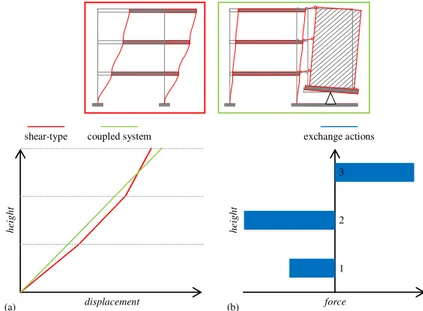
Figure 1-25 Upgrades of the base rocking systems proposed by Wiebe and Christopoulos (a) and by Wiebe et al. (b) ______________________________________ 25 Figure 1-26 EDLRF system proposed by Wu and Lu ____________________________ 26 Figure 2-1 External dissipative rocking system _________________________________ 27 Figure 2-2 Deformed shape of the overall system in the case of infinitely stiff bracing __ 28 Figure 2-3 Shear-type structure coupled with an infinitely stiff system: (a) modal
displacements, (b) exchange actions ______________________________ 28 Figure 2-4 Cantilever structure coupled with an infinitely stiff system: (a) modal
displacements, (b) exchange actions ______________________________ 29 Figure 2-5 Dissipative rocking system alternative configurations: (a) planar solution, (b)
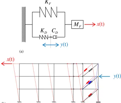
three-dimensional arrangement __________________________________ 30 Figure 2-6 Details of the building-tower connection _____________________________ 30 Figure 2-7 Dissipative towers configuration for the retrofit of the "Varano" High School 31 Figure 2-8 Details of the tower base and explanation of the leverage system __________ 31 Figure 2-9 Mechanical scheme of the coupled system ____________________________ 32 Figure 2-10 Proportional damping trend compared with those related to mass-proportional
and stiffness-proportional damping _______________________________ 33 Figure 2-11 Displacements of the active degrees of freedom and displacements related to
bracing deformation: (a) mechanical scheme, (b) external solution ______ 34 Figure 2-12 Deformed shape due to the coupling with an infinitely stiff system ________ 35 Figure 2-13 Displacements relof the active DOFs and displacement related to bracing
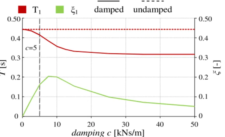
deformation in the case of the simplest mechanical system _____________ 39 Figure 2-14 Period and modal damping trend for different values of stiffness k1 _______ 41
Figure 2-15 Period and modal damping trend for increasing values of damping c _____ 41 Figure 2-16 Comparison of the fifth floor displacement responses (a) and of the fifth floor
absolute accelerations _________________________________________ 46 Figure 3-1 Van Nuys Building: (a) planar view and (b) transverse section ___________ 50 Figure 3-2 Van Nuys building foundation plan _________________________________ 51 Figure 3-3 First floor architectural plan (Rissman and Rissman Associates) __________ 51 Figure 3-4 Second floor architectural plan (Rissman and Rissman Associates) ________ 52 Figure 3-5 Structural damages on the South A facade of the Van Nuys Building, after
Northridge earthquake, detected by Trifunac et al. in the survey of 04/02/1994 ___________________________________________________________ 53 Figure 3-6 Structural damages on the North D facade of the Van Nuys Building, after
Northridge earthquake, detected by Trifunac et al. in the survey of 04/02/1994 ___________________________________________________________ 54 Figure 3-7 Pseudo-acceleration response spectra describing the seismic scenario _____ 54 Figure 3-8 Steps for the mass matrix construction ______________________________ 55 Figure 3-9 Steps for the stiffness matrix construction ____________________________ 56 Figure 3-10 Van Nuys building retrofit configuration ____________________________ 57 Figure 3-11 Planar view (a) and longitudinal section (b) of the bare building _________ 59 Figure 3-12 Camerino building retrofit configuration ___________________________ 60 Figure 4-1 Van Nuys building: interstorey drifts along the building height for mode 1 (a),
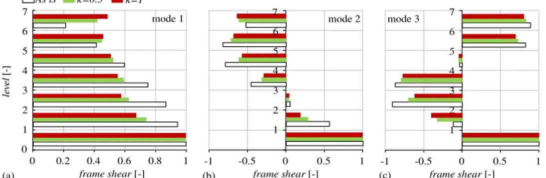
mode 2 (b) and 3 (c) ___________________________________________ 64 Figure 4-2 Van Nuys building: comparison of the shear force resisted by the frame for
Figure 4-3 Van Nuys building: shear force distribution for mode 1 (a), mode 2 (b) and 3 (c) in the
κ
=
1
retrofit case _______________________________________ 65 Figure 4-4 Van Nuys building: first three period trends in the retrofit caseκ
=1 ______ 66 Figure 4-5 Van Nuys building: comparison of the first three modes damping trends for bothκ
=1 andκ
=0.5 configurations _________________________________ 66 Figure 4-6 Van Nuys building: ρ-index trend comparison for increasing damping levels forboth
κ
=1 andκ
=0.5 configurations _____________________________ 67 Figure 4-7 Van Nuys building: ρ-index values for the seven modes of the system in theretrofit case
κ
=1 andξ
add=0.3 _________________________________ 67 Figure 4-8 Van Nuys building retrofitκ
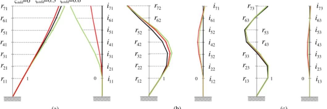
=1 configuration: real and imaginary part of thecomplex eigenvectors for increasing values of damping (a) first mode (b) second mode (c) third mode _____________________________________ 68 Figure 4-9 Camerino building: interstorey drifts distributions for mode 1 (a), mode 2 (b)
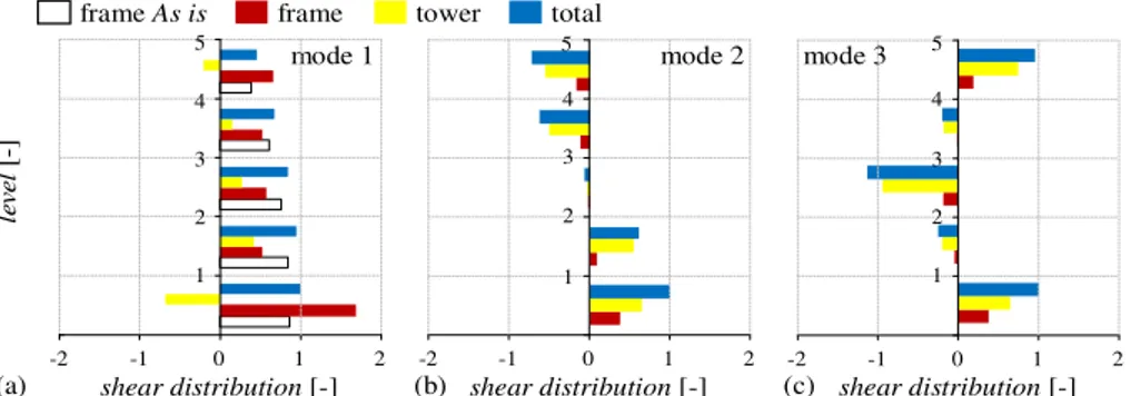
and 3 (c) ____________________________________________________ 71 Figure 4-10 Camerino building: shear action resisted by the frame for mode 1 (a), mode 2
(b) and 3 (c) __________________________________________________ 71 Figure 4-11 Camerino building: shear force distribution for mode 1 (a), mode 2 (b) and 3
(c) in the Retrofit configuration __________________________________ 71 Figure 4-12 Camerino building: first three periods trends (a) and comparison of the first
three damping ratio trends (b) ___________________________________ 73 Figure 4-13 Camerino building ρ-index: trend for increasing damping level (a) and values
of the five modes of the system for an added damping of 0.20 (b) ________ 73 Figure 4-14 Camerino building Retrofit configuration: real and imaginary part of the
complex eigenvectors for increasing values of damping (a) first mode (b) second mode (c) third mode _____________________________________ 74 Figure 5-1 Van Nuys building: displacements (a) and interstorey drifts (b) distributions for
the five configurations analyzed __________________________________ 77 Figure 5-2 Van Nuys building: contribution of the first mode to the full response in terms of
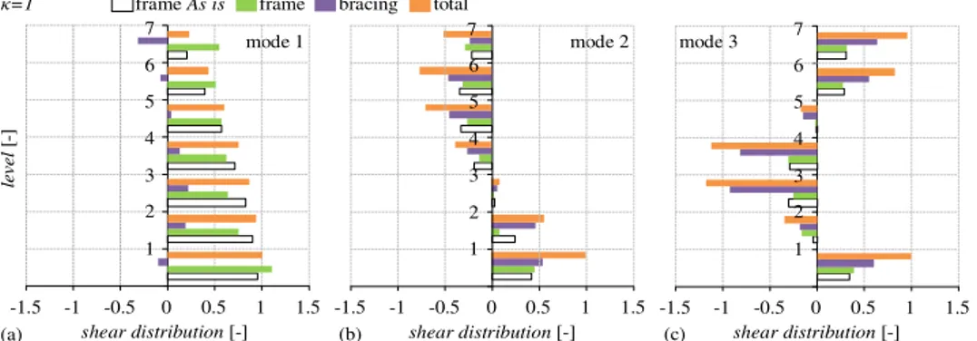
displacements for different analyzed configurations ___________________ 78 Figure 5-3 Van Nuys building: shear actions resisted by the frame (a) and by the tower (b) ____________________________________________________________ 80 Figure 5-4 Van Nuys building: shear actions resisted by the tower and the frame compared
to the total one in all the retrofit cases _____________________________ 80 Figure 5-5 Van Nuys building: first mode contribution on the shear response of the frame,
due to all modes, for different analyzed configurations ________________ 82 Figure 5-6 Van Nuys building: first mode contribution on the total shear response of the
tower for different retrofit analyzed configurations ___________________ 83 Figure 5-7 Van Nuys building: exchange forces distribution along the height of the building ____________________________________________________________ 84 Figure 5-8 Van Nuys building: comparison of the velocities distribution along the height 85 Figure 5-9 Van Nuys building: absolute acceleration distribution along the height _____ 86 Figure 5-10 Camerino building: displacements (a) and interstorey drifts distributions (b)
for the analyzed configurations ___________________________________ 88 Figure 5-11 Camerino building: contribution of the first mode to the full response of the (a)
Figure 5-12 Camerino building: (a) shear actions resisted by the frame in all the cases and (b) shear actions resisted by the tower in the three retrofit configurations _ 90 Figure 5-13 Camerino building: shear actions resisted by the tower and the frame, with
respect of the total one for (a) Retrofit 1F, (b) Retrofit and (c) Stiff cases __ 91 Figure 5-14 Camerino building: first mode contribution on the total frame shear response
in the (a) As is, (b) Retrofit 1F and (c) Retrofit cases _________________ 92 Figure 5-15 Camerino building: first mode contribution on the total tower shear response
in the (a) Retrofit 1F and (b) Retrofit cases _________________________ 93 Figure 5-16 Camerino building: first mode contribution on the full response of the total
shear in the (a) Retrofit 1F and (b) Retrofit cases ____________________ 93 Figure 5-17 Camerino building: tower-frame exchange forces distribution along the height
of the building ________________________________________________ 94 Figure 5-18 Camerino building: velocities distribution along the building height for all the
four configurations analyzed ____________________________________ 95 Figure 5-19 Camerino building: absolute accelerations distribution along the building
height for all the four configurations analyzed ______________________ 95 Figure 6-1 Harmonic transfer function behaviour compared with the input approximated as
a white noise random process from Barbato 2010 ____________________ 99 Figure 6-2 Van Nuys building: floor displacements resulting from a parametric analysis
involving different soil conditions _______________________________ 104 Figure 7-1 Linear and non-linear FVDs force-displacement loops for the CPLS (a) and
IOLS (b) ___________________________________________________ 107 Figure 7-2 Van Nuys building: FVDs force-displacement loops for record n. 12 ______ 110 Figure 7-3 Van Nuys building: FVDs force-displacement loops for record n. 15 ______ 111 Figure 7-4 Camerino building: pseudo-acceleration response spectra describing the
seismic hazard ______________________________________________ 112 Figure 7-5 Camerino building: FVDs force-displacement loops for the seven earthquakes
at the SLO __________________________________________________ 114 Figure 7-6 Camerino building: FVDs force-displacement loops for the seven earthquakes
at the SLD __________________________________________________ 116 Figure 7-7 Camerino building: FVDs force-displacement loops for the seven earthquakes
at the SLV __________________________________________________ 118 Figure 7-8 Camerino building: FVDs force-displacement loops for the seven earthquakes
at the SLC __________________________________________________ 120 Figure 7-9 FVDs used for the coupling with external stiff contrasting structure (a) and for
the coupling of adjacent buildings (b) ____________________________ 121 Figure 7-10 MPD systems: displacements (a) and interstorey drifts (b) distributions __ 123 Figure 7-11 MPD systems: shear actions resisted by the frame (a) and by the external
structures (b) _______________________________________________ 124 Figure 7-12 MPD systems: shear actions resisted by the external structure and the frame
compared to the total one ______________________________________ 125 Figure 7-13 MPD systems: comparison of the velocities distribution along the height _ 125 Figure 7-14 MPD systems: absolute acceleration distribution along the height ______ 126 Figure 7-15 MPD systems: FVDs axial actions distribution along the height ________ 127 Figure 7-16 External stiff systems comparison: displacements (a) and interstorey drifts (b) __________________________________________________________ 128
Figure 7-17 External stiff systems comparison: shear actions resisted by the frame (a) and by the external dissipative structures (b) __________________________ 129 Figure 7-18 External stiff systems comparison: shear actions resisted by the external
structure and the frame compared to the total one in the two retrofit analyzed cases ______________________________________________________ 130 Figure 7-19 External stiff systems comparison: velocities distribution along the height _ 130 Figure 7-20 External stiff systems comparison: absolute acceleration distribution along the
height ______________________________________________________ 131 Figure 7-21 SSI direct approach scheme _____________________________________ 133 Figure 7-22 SSI substructures approach _____________________________________ 134 Figure 7-23 Deep foundations layout (a) and related LPMs scheme (b) as proposed by
Carbonari et al. (2012) ________________________________________ 135 Figure 7-24 Foundations system planar view _________________________________ 136 Figure 7-25 Transverse section of the overall structural system ___________________ 136 Figure 7-26 Comparison of the 7th floor displacements on a fixed base and on compliant
base _______________________________________________________ 138 Figure 7-27 Comparison of the 7th floor absolute accelerations on a fixed base and on
compliant base ______________________________________________ 138 Figure 7-28 Comparison of the base shear resisted by the frame on a fixed base and on
List of Tables
Table 1-1 Interstorey drift-performance level relationship from Vision 2000 SEAOC ___ 10 Table 1-2 Earthquake hazard levels from Vision 2000 SEAOC _____________________ 10 Table 3-1 Earthquake recorded through the Van Nuys Building instruments __________ 52 Table 3-2 Geometrical properties of the external dissipative rocking system for all the
retrofit configurations considered _________________________________ 58 Table 4-1 Van Nuys building: modal analysis results of the bare building ____________ 63 Table 4-2 Van Nuys building: modal analysis results of the retrofit case
κ
=0.5 _______ 63 Table 4-3 Van Nuys building: modal analysis results of the retrofit caseκ
=1 ________ 63 Table 4-4 Van Nuys buildingκ
=1-ξadd=0.3 configuration: polar form of the first threeeigenvectors pairs for increasing values of damping __________________ 69 Table 4-5 Camerino building: modal analysis results of the As is configuration ________ 69 Table 4-6 Camerino building: modal analysis results of the Retrofit 1F configuration ___ 70 Table 4-7 Camerino building: modal analysis results of the Retrofit configuration _____ 70 Table 4-8 Camerino building Retrofit configuration: polar form of the first three
eigenvectors pairs for increasing values of damping __________________ 74 Table 5-1 Van Nuys building: floor displacements and drifts results _________________ 77 Table 5-2 Van Nuys building: higher order modes contribution on floor displacements and
drifts results __________________________________________________ 78 Table 5-3 Van Nuys building: shear actions results ______________________________ 79 Table 5-4 Van Nuys building: higher order modes influence on the shear actions resisted by
the frame ____________________________________________________ 81 Table 5-5 Van Nuys building: higher order modes influence on the shear actions resisted by
the tower ____________________________________________________ 81 Table 5-6 Van Nuys building: higher order modes influence on the total shear actions __ 82 Table 5-7 Van Nuys building: exchange forces results between frame and tower _______ 84 Table 5-8 Van Nuys building: floor velocities results ____________________________ 84 Table 5-9 Van Nuys building: absolute accelerations ____________________________ 85 Table 5-10 Van Nuys building: viscous dampers results __________________________ 86 Table 5-11 Camerino building: floor displacements and drifts results _______________ 87 Table 5-12 Camerino building: higher order modes contribution on floor displacements 89 Table 5-13 Camerino building: shear actions results ____________________________ 90 Table 5-14 Camerino building: higher order modes influence on the shear actions _____ 92
Table 5-15 Camerino building: exchange forces results between frame and tower _____ 94 Table 5-16 Camerino building: floor velocity distribution ________________________ 94 Table 5-17 Camerino building: floor absolute accelerations distribution ____________ 95 Table 5-18 Camerino building: viscous dampers results__________________________ 96 Table 6-1 Parameters of the Kanai-Tajimi spectra for various soil conditions ________ 103 Table 6-2 Van Nuys building: displacements results for different soil conditions ______ 104 Table 7-1 Van Nuys building: FVDs results for the record n.12 ___________________ 109 Table 7-2 Van Nuys building: floor displacements for the record n.12 ______________ 110 Table 7-3 Van Nuys building: FVDs results for the record n.15 ___________________ 110 Table 7-4 Van Nuys building: floor displacements for the record n.15 ______________ 111 Table 7-5 Camerino building: FVDs results for the SLO ________________________ 112 Table 7-6 Camerino building: floor displacements for the SLO ___________________ 114 Table 7-7 Camerino building: FVDs results for the SLD ________________________ 114 Table 7-8 Camerino building: floor displacements for the SLD ___________________ 116 Table 7-9 Camerino building: FVDs results for the SLV_________________________ 117 Table 7-10 Camerino building: floor displacements for the SLV __________________ 118 Table 7-11 Camerino building: FVDs results for the SLC _______________________ 119 Table 7-12 Camerino building: floor displacements for the SLC __________________ 120 Table 7-13 MPD systems: floor displacements and drifts results __________________ 123 Table 7-14 MPD systems: shear actions results _______________________________ 124 Table 7-15 MPD systems: floor velocities results ______________________________ 125 Table 7-16 MPD systems: absolute accelerations ______________________________ 126 Table 7-17 MPD systems: viscous dampers results _____________________________ 127 Table 7-18 External stiff systems comparison: floor displacements and drifts results __ 128 Table 7-19 External stiff systems comparison: shear actions results _______________ 129 Table 7-20 External stiff systems comparison: floor velocities results ______________ 130 Table 7-21 External systems comparison: absolute accelerations _________________ 131 Table 7-22 External systems comparison: viscous dampers results ________________ 132 Table 7-23 Existing frame-external rocking bracings exchange actions _____________ 132 Table 7-24 Soil site features ______________________________________________ 137 Table 7-25 Floor displacements and IDR comparison __________________________ 137 Table 7-26 Floor absolute acceleration comparison ____________________________ 138 Table 7-27 Comparison of the shear resisted by frame __________________________ 139
Abstract
In this thesis the seismic performance of existing buildings frames coupled with an external dissipative rocking system is investigated; the arrangement consists of a steel truss, hinged at the foundation level, whose rocking motion promotes the dissipation of energy via viscous dampers located at the base. Under the assumption of linear elastic behaviour of both the frame and the dissipative structure, the equation of motion of the system are presented, together with a generalized Single Degree of Freedom (S-DOF) approximation of the system. This way, analysis through time-domain and frequency-domain are allowed for the investigation of the system dynamic behaviour.
Time-domain analysis, based on a state space approach, leads to the complex modal analysis of the coupled system, which allows the evaluation of the influence of the added damping and of the displacements linearization, promoted by the external dissipative rocking system, on both the dynamic behaviour and the seismic response. In particular, the proposed formulation permits to evaluate separately the contribution of each of the complex vibration modes of the system to the global seismic response. On the other hand frequency-domain analysis is particularly useful for the problem under investigation because it allows to work with an algebraic system rather than a differential one. Furthermore by representing the seismic input in terms of a stationary stochastic process, a relation can be established between the Power Spectral Density (PSD) of the input and that of the response parameters of interest via harmonic analysis of the system.
The performance of two case studies is evaluated by means of parametric analysis, involving added damping and stiffness, either through time- and frequency-domain. Finally, some aspects which need a deeper investigation are presented. Among them the evaluation and comparison between linear and non-linear fluid viscous dampers, dimensioned through dissipated energy criterion. The performance of the analyzed dissipative system, is compared with an alternative retrofitting configuration, consisting in the coupling with external stiff contrasting structure, known in literature as mass proportional damping system. At the end a first insight on the effects of Soil-Structure-Interaction (SSI), through the substructure approach, is provided.
Keywords: Passive Seismic Protection, External Seismic Retrofit, Rocking Motion, Fluid Viscous Dampers, Dissipative Tower.
Sommario
Questa tesi ha l'obiettivo di indagare il comportamento dinamico e sismico di edifici esistenti protetti con un sistema esterno di dissipazione basato sul rocking; esso è costituito da una struttura reticolare in acciaio, incernierata a livello di fondazione, il cui movimento oscillante attiva la dissipazione di energia, per mezzo di smorzatori viscosi situati alla base. Nell'ipotesi di comportamento elastico lineare sia del telaio, che della struttura dissipativa, vengono presentate l'equazione del moto del sistema accoppiato ed una generalizzazione del sistema ad un grado di libertà. Per risolvere il problema dinamico è possibile condurre analisi sia nel dominio del tempo, che in quello delle frequenze.
La soluzione nel dominio del tempo si basa su una formulazione alle variabili di stato che, tramite analisi modale complessa del sistema telaio da proteggere-struttura esterna di protezione passiva, permette di valutare l'influenza, sia sul comportamento dinamico che in termini di risposta sismica, dello smorzamento e della linearizzazione degli spostamenti forniti dalla struttura dissipativa. In particolare, la formulazione proposta, consente di valutare separatamente il contributo di ciascuno dei modi di vibrazione complessi del sistema sulla risposta sismica globale. Le analisi armoniche nel dominio delle frequenze, invece, sono particolarmente utili in quanto consentono di lavorare con un sistema algebrico piuttosto che differenziale. Inoltre, scegliendo di rappresentare l'input sismico come un processo stocastico stazionario, è possibile stabilire una relazione tra la densità spettrale di potenza (PSD) dell'input esterno e quella dei parametri di risposta di interesse, tramite analisi armonica del sistema.
Le prestazioni di due casi di studio sono valutate mediante analisi parametriche, riguardanti diversi livelli di smorzamento e rigidezza del sistema di protezione, sia con analisi nel tempo che in frequenza. Infine vengono presentati alcuni aspetti che necessitano di ulteriore approfondimento. Tra di essi la valutazione ed il confronto della performance sismica di smorzatori viscosi a comportamento lineare e non, dimensionati attraverso il criterio di uguaglianza dell'energia dissipata. Le prestazioni del sistema di protezione passiva indagato, vengono confrontate con un'altra configurazione esterna, che prevede l'accoppiamento del telaio con una struttura rigida di contrasto, nota in letteratura come sistema di smorzamento proporzionale alle masse. Infine viene condotta una prima analisi degli effetti dell'interazione terreno-struttura (SSI), mediante l'approccio alle sottostrutture.
Keywords: Sistemi Passivi di Protezione Sismica, Adeguamento Esterno, Moto di Rocking, Dissipatori Viscosi, Torri Dissipative.
Introduction
The challenge of gaining the seismic protection of both new and existing structures is a very current problem nowadays in Italy; not only for recent frequent seismic crises (L'Aquila 2009, Emilia 2012, central Italy 2016) with related losses in terms of human beings, but above all for the poor quality of a large part of the building heritage. Within it r.c. frame buildings built without seismic standards or with details inadequate to modern codes can be considered. In case of severe earthquakes, the poor quality of many structures can leads to more losses in terms of lives and of architectural and historical goods and to high socio-economic costs related to factories downtime. Hence the necessity of doing interventions towards seismic protection is a very fascinating target.
Towards the goal of the achievement of the seismic protection Performance Based Design Approach has become the design philosophy in the last few years. This method relates the performance objectives of a structure to the probability of occurrence of earthquakes, therefore different Limit States (LS), as a function of the importance of the facility itself; the aim is to avoid catastrophic failures, loss of lives and keep the construction costs under control. This means that strategical structures, like hospitals, fire stations or schools are expected to remain functional immediately after a severe earthquake, while basic facilities must still be able to sustain gravity loads even though they can undergo severe damages to the frame members. Hence structures are evaluated also through an economic point of view, in terms of costs for the society, keeping in mind that, for mission-critical structures, the structural cost it is just a small percentage of the overall cost, which also accounts for contents and non structural components. The performance achievement can be guaranteed through many techniques, which can be either traditional, Capacity Design, or more recent, like Seismic Isolation and/or Passive Supplemental Damping. In the recent past, many studies have proven the efficiency of passive control systems (Soong and Dargush 1997, Soong and Spencer 2002, Christopoulos and Filiatrault 2006).
Within Passive Supplemental Damping field there are many structural configurations available based on the use of different devices, that can be grouped into three main categories: hysteretic dampers, viscous and visco-elastic dampers and recentering systems (smart materials or post-tensioned mechanisms based on rocking motion). Traditionally passive damping devices are installed within a building frame in either diagonal or chevron brace configurations connecting adjacent storeys; dynamic properties of the damped system
and design methods have been implemented through many studies (e.g. Whittle et al. 2012, Di Cesare et al. 2012, Ponzo et al. 2012 Hwang et al. 2013, Lavan et al. 2013, Dall'Asta et al. 2016). Nevertheless this type of damping system may present some disadvantages, especially when employed for the retrofit of existing buildings, like the increase of internal actions in the columns with induced premature local failures (Freddi et al. 2012), the need of localized strengthening of foundations and the indirect costs related to the interruption and/or relocation of internal activities, which are significant especially for relevant structures. Therefore the use of external passive control system is becoming more and more frequent thanks to the fact that their interferences with existing frames, internal activities and related indirect costs, are notably reduced. Among the external intervention possibilities there is also the coupling of two adjacent buildings by placing dampers between them; the efficiency of this solution is guaranteed if the two structures have strongly different dynamic behaviours (Gattulli et al. 2013, Tubaldi et al. 2014, Tubaldi 2015).
This thesis seeks to investigate the dynamic behaviour of an alternative retrofit configuration, which can be called external dissipative rocking system. The proposed system, permits to gain the seismic protection of an existing frame building by exploiting the rocking motion of a stiff brace hinged at the foundation level to activate fluid viscous dampers (FVD), located at the base, for the energy dissipation. The rocking configuration can be used either in planar and spatial arrangements. Recently, some applications of such kind of systems have been developed (Roia et al. 2013, Roia et al. 2014) and are known as "dissipative towers", which is a patented solution (Balducci 2005).
Even if spherical hinges and viscous dampers are already widely employed in civil engineering applications and rocking motion is usually associated to recentering systems, the main objective of this thesis is to investigate the dynamic behaviour and the seismic response of frame buildings protected by means of the external dissipative rocking system. To reach this target the analysis of the dynamic performance in terms of modal properties is conducted, with a separate evaluation of stiffness and damping contribution. It is important to specify that the stiffness addition has to be intended only in terms of linearization of the displacements distribution. The seismic response is evaluated via modal decomposition method, through the monitoring of relevant engineering demand parameters (EDPs). With the aim to provide some useful tools necessary to the design of the system, which are already available for traditional retrofitting techniques, it is necessary to identify an optimal tower-to-frame stiffness ratio range, which is a meaningful parameter of the effectiveness of the linearization of displacements distribution. For what concern damping contribution it is important to check if the estimate of damping ratio obtained by employing approximate formula reported in current codes, can be valid also for the design of devices located at the base of the dissipative system. Moreover it is also necessary to identify the range in which the damping provided by the rocking system is effective.
Once defined the thesis objectives it is necessary to identify the way to reach them; for this purpose a formulation involving the coupling with the external dissipative rocking system is proposed and the related equation of motion is stated in matrices form. It is noteworthy that the proposed formulation is defined in general terms, therefore can be useful also for other external passive control systems. To find a solution to the dynamic problem, two alternative ways are shown, the first one is through time-domain, while the second is through frequency domain.
The thesis dissertation is organized in seven chapters, Chapter 1 provides an overview of the seismic passive control systems available. A brief recall on principal damping devices preludes to the possible structural configurations description and related state of the art. Finally the investigated system, external dissipative rocking system, is introduced.
In Chapter 2 the main features of the analyzed system are shown. The effects of added stiffness are explained in terms of linearization of displacements distribution along the building height, before and after the coupling, for two limit configurations: a shear-type structure and a cantilever frame. The problem formulation is stated in matrix forms and the equation of motion are presented, assuming that the existing frame and the external dissipative rocking structure exhibit a linear elastic behaviour. Moreover, proposed formulation accounts for the non-classical damped nature of the coupled system due to the concentrated location of the dampers at the base of the dissipative system. The equation of motion for a generalized SDOF approximation, dealing with the limit case of coupling with an infinitely stiff rocking system, is shown. For this particular configuration the displacements field is constrained through the base rotation of the bracing. Two ways to find a solution for the dynamic problem are introduced, the first one deals with Time-domain analysis and is presented in terms of a state-space formulation; the second one deals with Frequency domain analysis. Finally an alternative formulation, proposed by Chu et al. 2009, which provides an extension to the concept of participant mass ratios related to underdamped complex and conjugate modes and over damped modes, is introduced.
In Chapter 3 two case studies are analyzed to exhibit the capability of the proposed formulation to investigate the dynamic behaviour of the coupled system existing building external dissipative rocking bracing. The first one is a seven storey benchmark structure, Van Nuys Building, already used as a testbed by the Pacific Earthquake Engineering Research Center (PEER) and widely analyzed thanks to the fact that this building was equipped with accelerometers and recording instruments since 1971 and it was struck by several earthquakes (e.g. San Fernando 1971 and Northridge 1994). The second case study is a five storey r.c. frame structure, representative of many buildings built in Italy during the '80s without seismic detailing, which is assumed to be located in Camerino, a small town in central Italy very close to the epicentre of the Marche-Umbria 1997 and central Italy 2016 earthquakes, therefore representative of an area characterized by an high seismic hazard. For both the two case studies modelling criteria and seismic hazards are introduced. In Chapter 4 the modal properties of the coupled system, existing frame plus external dissipative rocking system, are highlighted for the two case studies and the variations of both the contributions, that is stiffness and damping, are separately analyzed. First of all the effect of added stiffness is shown on the interstorey drifts distribution and on the shear action resisted by the frame along the building height. Parametric analysis are also performed by varying the tower-to-frame stiffness ratio. The effects of increasing level of added damping are also evaluated through the monitoring of deformed shapes and damping ratios associated to each vibration mode.
In Chapter 5 the seismic responses of the two analyzed case studies are shown and their performance is evaluated through monitoring of engineering demand parameters (EDP's), i.e. displacements and interstorey drifts, which are representative of the structural and non structural damages; shear actions distribution, for the monitoring of new and existing foundations; velocities and absolute accelerations whose monitoring is important for the contents. Moreover everything dealing with viscous dampers (displacements, velocities, axial actions and viscous bending moment) which are representative of their costs and
necessary for the design of the external bracings foundations. The higher order modes contribution on the overall responses are also evaluated.
Chapter 6 illustrates a frequency domain analysis of the seismic problem. This type of analysis is particularly useful for the problem at hand because it allows to work with an algebraic system rather than a differential one. Another advantage of working in the frequency domain is that by representing the seismic input in terms of a stationary stochastic process, a relation can be established between the Power Spectral Density (PSD) of the input and that of the response parameters of interest via harmonic analysis of the system.
Chapter 7 deals with further issues, involving the analyzed system, required for a complete analysis of its potentialities. Preliminary results of the main open problems are shown. Among them the performance of non-linear fluid viscous dampers, dimensioned through equating dissipated energy criterion, for a given Limit State (LS). A comparison of the performance of an alternative external configuration is evaluated for the Van Nuys building case study, by assuming the same contribution of added damping (ξ=30%). The alternative solution consists in the coupling with external stiff contrasting structure, known in literature as mass proportional damping system. Finally a first insight on the effects of Soil-Structure-Interaction (SSI), through the substructure approach, is provided for the Van Nuys building case study.
Chapter 1
Seismic Passive Control Systems
The achievement of the seismic protection of both new and existing structures is an important target for structural engineers, since it permits to avoid catastrophic losses and guarantee human beings protection. Moreover, in the last thirty years the awareness that the question does not involve only structural engineers, but also owners and the overall community is becoming more and more strong.
When a severe earthquake hits a country the cost is not only related to loss of life, but also to loss of architectural and historical goods and even to high socio-economic costs related to services and factories downtime and moreover to the cost of repair, which could be extremely high. Thus the concepts of performance and, more in detail, expected performance have been introduced, together with a design philosophy known as Performance Based Design.
Performance Based Design approach is a general philosophy according to which design criteria of structures are expressed as stated performance to reach for stated probabilities of occurrence of earthquakes. The performance target can be represented by any response parameter related to a certain threshold, because a single design parameter may not provide an adequate control of all the performance objectives for structural and non-structural components. The Performance Based Design method arises from the evaluation and upgrade process for existing buildings and its origin derives from Applied Technology Council ATC-33 project, sponsored in the USA by the Federal Emergency Management Agency (FEMA), for the development of a national guidelines for the seismic retrofit of buildings, then adopted and extended to the design of new buildings by Structural Engineers Association of California (SEAOC) in its Vision 2000 project. This approach aims not only to relate performance objectives of both structural and non structural elements, expressed as acceptable levels of damage, with the earthquake occurrence probability, but also to adjust them as a function of the importance of the structure in itself. The result is a performance-based design matrix shown in Figure 1-1 and adapted from the Vision 2000, SEAOC. Table 1-1 derives from the same document and relates performance levels to interstorey drift ratios and structural and non-structural damages description. Similarly, Table 1-2 reports the earthquake classification based on the definition of both return period as the average time span between shaking intensity that is equal to or greater
than a specified value, and probability of exceedance, which is the annual frequency of exceeding a given intensity.
Fully Operational Performance objective E a rt h q u a k e p ro b a b il it y Frequent Occasional Rare Very rare
Operational Life Safety Near Collapse
unacceptable performance
Safety Critical Facilities Essential/Hazardous Facilities
Basic Facilities
Figure 1-1 Performance Based Design matrix
Table 1-1 Interstorey drift-performance level relationship from Vision 2000 SEAOC
Performance
level Drift % Description
Fully
Operational 0.2 Continuous service. Negligible structural and non-structural damage.
Operational 0.5
Most operations and functions can resume immediately. Structure safe for occupancy. Essential operations protected, non-essential operations disrupted. Repair required to restore some non-essential services. Damage is light.
Life Safety 1.5
Damage is moderate, but structure remains stable. Selected building systems, features or contents may be protected from damage. Life safety is generally protected. Building may be evacuated following earthquake. Repair possible, but may be economically impractical. Near
Collapse 2.5
Damage severe, but structural collapse prevented. Non-structural elements may fall.
Table 1-2 Earthquake hazard levels from Vision 2000 SEAOC
Earthquake classification Return Period
[years] Probability of exceedance
Frequent 43 50% in 30 years
Occasional 72 50% in 50 years
Rare 475 10% in 50 years
Hence it is observable that strategical structures, like hospitals, fire stations or schools are expected to remain functional immediately after a severe earthquakes, while basic facilities must still be able to sustain gravity loads even though they can undergo severe damages to the frame members, therefore their repair is not convenient. This leads also to an economical evaluation of structures in terms of overall cost, keeping in mind that, for essential structures, the structural cost it is just a small percentage of the overall cost. Taghavi and Miranda proposed an accurate evaluation of this concept in their report
Response assessment of non-structural building elements (PEER 2003) from which Figure 1-2 derives. The comparison of the structural, non structural and contents cost is provided for three kind of structures, an office, an hotel and an hospital. In general, the structural cost is limited into 20% and the percentage is even more reduced for the hospital case, where the cost of contents is highly significant. It is noteworthy that the non structural components represent the major cost (nearly higher than 50%).
0% 20% 40% 60% 80% 100% structural non structural contents
office hotel hospital
Figure 1-2 Cost components comparison among offices, hotels and hospitals proposed by Taghavi and Miranda 2003
The seismic protection of structures can be guaranteed through traditional techniques, like Capacity Design, or other solutions like Passive Control Systems, which do not need of external power sources to provide their contributions. Among them:
1 Seismic Isolation;
2 Passive Supplemental Damping.
Capacity Design is a design approach wherein the structure is configured to concentrate yielding and inelastic behavior in specific locations, plastic hinges, where elements are detailed to reliably exhibit such behavior, and which, through their ductile behavior, limit the demands on other portions of the structure that are designed with sufficient strength to remain essentially elastic during earthquake response, as shown by the sketch of Figure 1-3 (a). Capacity Design technique is usually related to the seismic design of basic facilities, while for the design and retrofit of strategic structures, like hospitals or schools, which must exhibit higher levels of performance (operational or fully operational for a rare earthquakes) the use of seismic isolation or passive supplemental damping is expected. Supplemental damping devices and/or seismic isolation are thought to be able to dissipate energy introduced in a system by seismic actions, instead of the frame members. Figure 1-3 (b) shows a possible configuration for supplemental damping devices, which are activated by the frame movement, while Figure 1-3 (c) depicts schematically seismic isolators, which
are located among the foundations and the superstructure, and whose task is to decouple motion between the ground and the frames.
(a) (b) (c)
Figure 1-3 Seismic protection techniques: (a) Capacity Design, (b) Supplemental Dampers, (c) Seismic Isolation
Seismic actions effects on a structure can be seen through an energy balance formulation as the one reported in Eqn. ( 1-1 ):
h v s k I
E
E
E
E
E
=
+
+
+
( 1-1 )where EI denotes earthquake input energy transmitted to a structure depending on its inherent properties, i.e. period of vibration; Ek is the kinetic energy produced by structural masses as a reaction to the seismic input energy; Es is the strain energy related to elements elastic deformation; Ev is the viscous damping energy representative of the dissipated amount of energy, thanks to the inherent damping of the structure and or to supplemental viscous dampers action; Eh is the hysteretic energy related to structural deformation in the inelastic range (damages), hence symbolizes energy dissipated by means of plastic hinges in the frame members. Supplemental damping, therefore, can be seen as a way to prevent structural members from damaging, while seismic isolation has to be seen as a way to reduce the amount of input energy entering in the structure, through the lengthening of the fundamental period.
1.1
Seismic isolation
Seismic isolation concept consists of decoupling the motion, induced by a seismic excitation, between the structure and the ground. Isolators can be of different types, but all characterized by a high vertical stiffness to sustain vertical loads and low lateral one, with respect to that of the superstructure, which leads to the lengthening of the structural system fundamental period. As a consequence, a simultaneous reduction of the absolute accelerations and a major request in terms of displacements are evident, as shown in Figure 1-4. To enhance the performance of the isolation system it is possible to use a combination of isolators and dampers, which provides a supplemental control of the total amount of displacements.
0 0.5 1.5 4 T [s] a c ce le ra ti o n [ g ] 0 0.1 0.2 0.3 0.4 0.5 0.6 0.7 1 ξ=5% 2 2.5 3 3.5 d is p la ce m en t [m ] 0 0.2 0.15 0.1 0.05 ξ=10% ξ=20%
Figure 1-4 Lengthening of the fundamental period due to seismic isolation
The main advantage of an isolation system is the high reduction of damage to structural and non-structural elements and to contents, with related savings in case of strong earthquake hitting essential structures. Moreover isolators provides a response regularization, especially in the case of irregular structures as those which displays torsional coupling; the superstructure members do not require special design of detailing, thanks to the fact that no plastic hinges are expected.
Usually isolators are placed under a very thick slab and over the supports, so they can be readily checked or substituted and maintenance operations are greatly simplified with respect to bracings, that are installed within the frames. On the other hand bidirectional seismic gaps are needed due to the displacements required, furthermore isolation effectiveness is reduced in the case of tall buildings and there are some design problem related to light upper structures like wooden and/or steel structural systems.
There are two main types of isolators which are widely used: laminated-rubber bearings and friction pendulum system (FPS). Elastomeric isolators are self-centering devices, they display an high stiffness for ordinary conditions, which is the same in the two main horizontal directions. Their performance is less influenced by time-dependence and their dimension is governed by gravity loads (axial action), lateral stiffness and by the maximum relative displacements between bearings upper and lower base (geometrical relationship). To enhance damping properties of elastomeric bearings a cylindrical lead core can be inserted in the isolator centre, which can yields for shear actions. Figure 1-5 (a) depicts the components of a rubber isolator (without lead core), while Figure 1-5 (b) displays a typical force-shear deformation hysteretic loop.
cover steel plates
protective rubber layer
thin steel layers rubber layers
(a) shear deformation γ
fo
rc
e
(b)
Friction pendulum isolators (FPSs), differently from elastomeric bearings, can have diverse periods between the two main directions of analysis, moreover they use gravity as a restoring force. Their stiffness is proportional to masses and their period do not depend on the structure features. This type of isolator may have some drawbacks, because they are partially restoring and they can have some problems with static friction with the consequence of a different behaviour than the predicted one. Figure 1-6 (a) and (b) display a double surface FPS and a dissipative friction rigid plastic hardening loop, respectively; in Figure 1-6 (b) µ denotes friction coefficient and W is the weight acting on the isolator.
displacement fo rc e (b) D F keff -F µW µ=friction coefficient spherical concave surfaces
double friction slider
(a)
-D
Figure 1-6 FPS: (a) double surface scheme, (b) force-displacement loop
1.2
Passive supplemental dampers
Supplemental dampers, whose efficiency in dissipating energy is expressed by the area included in one complete cycle of vibration, can be divided into three main categories:
1 Hysteretic Dampers;
2 Viscous and Visco-elastic Dampers; 3 Recentering systems.
The latter category is based on flag-shaped model for energy dissipation that can be achieved either by shape memories alloys and by post-tensioned rocking mechanisms.
1.2.1
Hysteretic Dampers
Hysteretic dampers are activated by relative displacements between connection points, among them there are friction devices, elasto-plastic and elasto-plastic hardening devices. Usually forces produced by these dampers are in phase with structural internal ones; their main positive features are a high dissipative capacity, a reduced economic cost and the fact that they are not velocity-, neither temperature-dependent. On the other hand, there are some uncertainties related to the time-dependent performance of friction devices, while the others need to be substituted after a certain number of cycles due to the low cyclic fatigue.
Figure 1-7 (a), (b) and (c) depicts hysteretic devices vibration cycles, where u denotes displacements and Fd dissipative forces.
(a) (b) (c) u Fd u Fd u Fd
Figure 1-7 Hysteretic dampers cycles: (a) friction, (b) elasto-plastic, (c) elasto-plastic hardening
1.2.2
Viscous and Visco-elastic Dampers
The second category of passive supplemental damping devices is represented by either visco-elastic and viscous dampers. Visco-elastic dampers are able to provide not only a velocity-dependent force, which adds supplemental damping to the structure, but also an elastic displacement-dependent force which allows the restoring of the system. Therefore visco-elastic dampers provids not only an enhancement of damping, but also an increasing in the stiffness of the overall structure, which could lead to higher values of absolute accelerations for the frames to protect (Figure 1-8). Whereas viscous dampers provides only a velocity-dependent force (based on the relative value of velocity between the two ends of the device), so, in order to guarantee recentering they need to be coupled with a structure providing restoring force. Viscous dampers do not need of substitution after seismic events, because they are able to experience a very high number of cycles.
0 0.5 1.5 4 T [s] a c c e le ra ti o n [ g ] 0 0.1 0.2 0.3 0.4 0.5 0.6 0.7 1 ξ=5% 2 2.5 3 3.5 ξ=10% ξ=20%
Figure 1-8 Effects of visco-elastic devices on the period of a structure
Figure 1-9 (a) depicts a visco-elastic device acting in shear, Figure 1-9 (b) shows a typical hysteretic cycle where it appears that maximum value of force is slightly out of phase with the maximum value of displacements.
(a) displacement [m] fo rc e [k N ] (b)
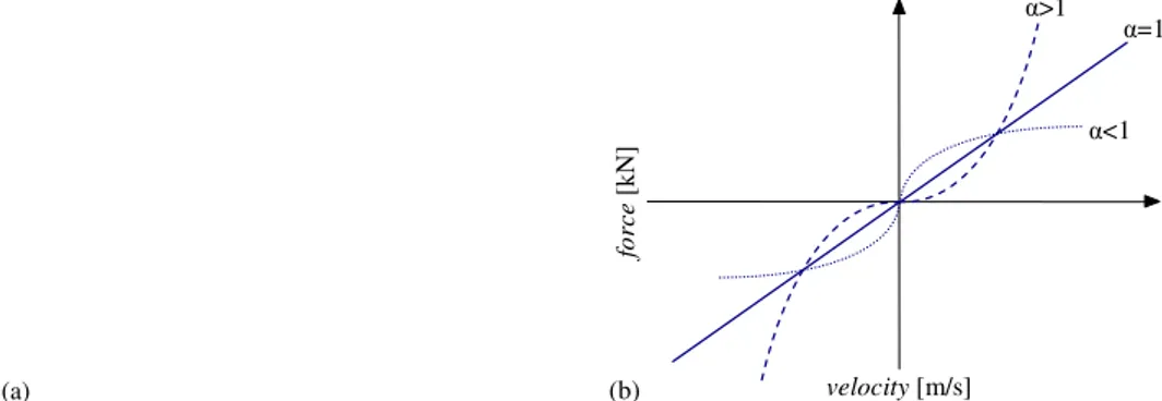
Figure 1-9 Visco-elastic damper acting in shear (a), force-displacement cycle (b) Fluid viscous dampers (FVDs) are particularly of interest not only for their features and their widely diffusion across Europe and North America, but also because they are an essential element of the dissipative rocking system, subject of this thesis. Forces produced by FVDs are related to velocities by the expression reported in Eqn. ( 1-2 )
( )
α αα
u
u
C
F
d=
ɺ sgn
ɺ
( 1-2 )where
F
d denotes damper dissipative axial force,C
α is the damping constant,uɺ
is therelative velocity between the two ends of the device and α is the exponent whose value determines the linear or non linear behaviour of the damper; when α is equal to unity there is a linear dependence between force and velocity. Usually for civil engineering applications α=1. Figure 1-10 (a) shows a FVD scheme and it is observable that this kind of device consists of a stainless steel piston with a bronze orifice head, filled with silicone oil. The piston head utilizes specially shaped orifices that alter the flow characteristics with fluid relative velocity; the force produced by the damper is generated by the pressure differential across the piston head, as well explained by Christopoulos and Filiatrault 2006. Figure 1-10 (b) displays force-velocity curves at various level of the exponent α and it is clear that non linear viscous dampers with α<1, display smaller forces for high values of velocity and higher displacements, with respect to linear FVD (α=1).
Figure 1-11 displays a comparison of the force-displacement loop for decreasing values of the exponent α, starting from unity, which means linear behaviour, until the value of
α=0. It is evident that for α=1 the loop has an elliptical shape with the highest values of
forces corresponding to the smallest values of displacements and vice versa. Generally for decreasing values of α forces generated by non-linear FVDs are still out of phase with those developed by the structure, but their cyclic response approaches the rectangular load-displacement shape of hysteretic dampers (limit case of α=0). Anyway, non-linear FVDs still exhibit forces that are linearly proportional to the damping constant
C
α to the power of α and to the displacements amplitude.(a) velocity [m/s] fo rce [ k N ] (b) α>1 α=1 α<1
Figure 1-10 FVD scheme (a), force-velocity curves for linear and non-linear FVDs (b)
displacement [-] fo rc e [-] α=1 α=0.2 α=0.6 α=0 0 -0.5 -1 0.5 1 0.5 1 -0.5 -1
Figure 1-11 Force-displacement loops for linear and non-linear FVDs
1.2.3
Recentering systems
Recentering systems are characterized by a flag-shaped loop, as the one depicted in Figure 1-12; this behaviour can be achieved principally in two ways, that is through shape memory alloys or through devices based on articulated mechanisms that aim to provide both energy dissipation and recentering. By observing the flag-shaped loop of Figure 1-12, where u denotes displacements and Fd dissipative forces, it is noteworthy that the amount of dissipated energy is reduced, when compared with an elasto-plastic hysteretic device, but the self-centering system returns to zero-force, zero-displacement position, not only at every cycle, but also at the end the seismic action.
Shape memory alloys (SMA) are a class of materials able to develop the so-called super-elastic behaviour; they are principally made of different metals, like nickel, titanium, zinc, copper and aluminium. Super-elastic behaviour is a process that involves the changing in chemical phases when the temperature of the alloying is increased, resulting in an hysteretic effect with near zero residual strain, as shown in Figure 1-12.
u Fd
Figure 1-12 Flag-Shaped hysteresis loop
An example of self-centering device is the Energy Dissipating Restraint (EDR) (Nims et al. 1993), shown in Figure 1-13. EDR incorporates a sliding friction mechanism with an internal end stop, limiting the range of motion. The friction develops at the interface between the bronze wedges and the steel cylinder, while an additive stiffness is provided by a helical spring coaxial to the steel cylinder.
Figure 1-13 EDR device proposed by Nims et al. 1993
Recently, a new Self-Centering Energy Dissipative (SCED) steel brace (Christopoulos et al. 2008) was proposed; this system involves element of traditional steel bracings, a dissipative mechanism and a tensioning system, used to provide a prestress to the SCED. This system is developed to exhibit the flag-shaped loop, undergoing large axial deformations, providing energy dissipation capacity and a self-centering behaviour. A concept of SCED device is reported in Figure 1-14.