ON THE DESIGN AND TESTING OF A RESEARCH DEVICE ABOUT
STREAMING WATER PHENOMENA
Stefano Uberti, Danilo Cambiaghi, Valerio Villa
Dipartimento di Ingegneria Meccanica
Facoltà di Ingegneria, Università degli Studi di Brescia
Via Branze, 38
25123 Brescia
Italy
[email protected]
ABSTRACT
The Group of Mechanical Design of the University of Brescia was charged with the task to develop, and design a large scale facility aimed to perform tests about streaming water phenomena, the final user being the Group of Civil Hydraulics of the same University. The facility has been designed, developed and successfully tested. It is mainly composed with a sub-horizontal channel, flat bottomed and transparent walled. The cross area of the streaming flow can be reduced and the slope can be controlled (0 to 7°).
Very severe requirements were foreseen with respect to smoothness and planarity (0.5 mm Vs 12 m length and 700 mm width). Acceptable deformations were limited to very slight values, although the length of the channel being remarkable and the expected loads being widely variable, due to the relevant range of foreseen speeds and flow rates of streaming water (sand and small stones transport by stream had been foreseen too).
To guarantee the required flatness along the whole channel a modular design has been adopted and proper means to adjust the fitting between contiguous modules have been developed. Notice the sealing must not be compromised in adjusting phase.
A mobile support free to be moved along the channel has been designed in order to allocate a number of measuring probes devoted to hydraulic phenomena monitoring.
An inlet tank was designed too, equipped with proper devices to guarantee a smooth and waveless inlet of water in the whole range of foreseen flow rates (up to 220 litres/s). An output tank was equipped with proper piping and pumping items to re-circulate the fallen water. Of course devices to precisely modify the slope rate were developed too. The facility has been installed and is nowadays in use for scientific and teaching purposes. In the proposed paper the following items will be dealt with: exact design requirements definition, study and design phases, solid modelling of the plant, building, trials and delivery, some considerations about using geometric and dimensional tolerancing (GD&T) on machine with relevant measures.
Keywords: water plant, test machine, streaming water phaenomena TECHNICAL SPECIFICATIONS
After analyzing the problem the design team helped the commissioner to define either an exhaustive list of technical requirements and a precise list of admitted mechanical and hydraulic interfaces. It is worthy pointing out how this phase may be delicate and problematic when dealing with people which are not familiar with industry procedures.
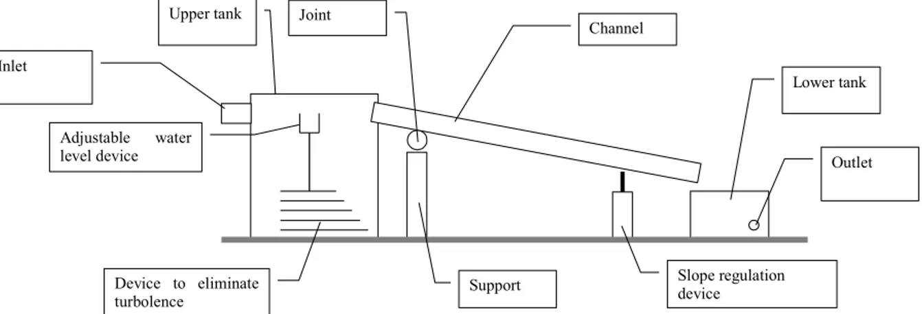
The facility must help studying streaming water phaenomena. The proposed lay out is represented in the following image Upper tank Device to eliminate turbolence Adjustable water level device Channel Support Joint Slope regulation device Lower tank Inlet Outlet
The plant is composed by (basic components) :Upper tank, Channel, Slope regulation device, Lower tank, Fittings-sealing- supports and so on, External recirculation device and Auxiliary tanks.
Later on the design team defined the basic characteristics of each component, as detailed in the following. 1) Upper Tank. Upper tank must contain 10.000 litres of water, it mustn’t be pressurized, and it should be divided into two compartments. In the first compartment water arrives from the auxiliary tank and/or from the recirculation device, while from the second compartment water flows to the channel. These two compartments are connected by a dedicated multi channel device aimed to “calm” the water to avoid vortexes and turbulences (for example a honeycomb feedthrough or a battery of tubes may be considered…).
Between the two compartments it should be interposed a device aimed to set the water height.
It is necessary that flowing water comes from a tank without any turbulence end with negligible flow rate to avoid that any flow energy may interfere with the theoretic height. The water level should be adjustable in a range of 0,5m. Adjusting must be performed without human help.
2) Channel. The channel must be 10-12 m long, featuring a rectangular 0,7m wide x 0,5m high section. Bottom must be in stainless steel, side walls must be glass made and there should be no roof. Channel bottom should be planar with a tolerance lower than 3mm on the entire length (12m), and lower than 0,5 mm on every meter of length. These values must not be exceeded neither in dormant nor in working conditions (up to 440kg of water for m of channel).
It must be possible to reduce the channel section adding a removable wall along the whole length, such wall being located in any transversal position in a range (step of 50 mm) so to reduce water flow section down to 400 mm minimum. In the channel bottom it should be possible to replace some standard panels with instrumented ones, without any impact on the planarity. Obviously there mustn’t be any leakage from the entire structure. On the upper side of the channel a rail will be located to run a chariot with several probes from a channel’s end to the other. It is assumed that the structure of the channel will experience no water induced vibration.
3) Support and slope regulation device. The whole channel should be properly supported by a structure featuring pivot point near to the upper tank while a slope regulation device should be positioned near the lower tank. This device should be constituted by an electromechanical or hydraulic jack to be controlled by a remote keyboard. It should be possible to increase the slope of the channel up to a difference of 700 mm in level between extremities.
4) Lower tank. Water flow coming from the channel must be collected into a lower tank, suited to accept the maximum water flux. It should be internally divided in some way to “calm” water flux coming from channel, and there must be a collector to transfer by gravity the inlet water to a buried tank.
Moreover there should be suitable fittings for a water recirculating system, whose capacity can be estimated in 80 liters/second.
5) Couplings, joints and fittings . Between upper tank and channel a connection deformable element should be interposed, so to lead water into channel without vortex and turbulences independently from channel slope. Suitable sealing must be foreseen to avoid leakages independently from channel’s slope, in static conditions or during slope variations. It must be possible to reduce the inlet connection in order to fit the channel section reductions. Between channel and lower tank we must foresee some connection element to accompany fluid flux to the tank, avoiding leakages and water sprays. Also that element should be reducible in relation with channel section reduction.
6) Secondary recirculation system. A recirculation system dimensioned for the maximum flow capacity (up to in 220 litres/second) would have been too demanding in terms of cost, dimensions and power consumption. Furthermore it may cause undesired turbulence in the upper tank to whom the flow would be directed. The recirculation system was consequently designed for the average flow, and for the exceeding needs a secondary system was designed, based on an auxiliary tank located under the floor level and fed by gravity.
A fourth tank located upstairs so to have a 5 meters overhead with respect to the plant room will be fed by a pumping system aimed to transfer, continuously and with small flow rate, the water from the under ground tank. Such tank will integrate the flow coming from the primary recirculation system. Proper dimensioning makes sure that the experiment time is covered with maximum requested flow rate.
Assembly. The facility we are speaking about had to be located in the hydraulic laboratory of the University of Brescia, the inlet passage being narrow and scarcely comfortable for encumbering items. It was mandatory to agree with the manufacturers to deliver the mechanics divided into semi integrated structures and to perform a late integration on the spot. The design was compliant with such program.
GENERAL ANALYSIS OF THE PROBLEM
In the following some of the difficulties of the design phase are listed. In fact there are similar plant in commerce, but this plant is more and more demanding in terms of maximum capacity and configurability. Furthermore some technical features, such as channel planarity, are outstandingly severe. Consequently it was necessary to start designing from scratch in order to set up a configuration in agreement with all the specifications defined in analysis phase.
The environment featured very challenging singularities, like a very low ceiling and a set of columns supporting the ceiling itself which in fact is the floor of other laboratories of the University. Furthermore the floor is carved by some huge diggings especially due to the underneath tank and piping.
Under the technical point of view the most challenging requirement was related to the planarity levels (3mm/12m, 0,5mm/1m) under minimum and maximum load conditions (0-220 l/s).
Adding the difficulties and especially the costs to machine such a large structure within such narrow tolerances to the difficulties of inserting the structure itself inside an uneasy to access location, the problem of the dimensions of the facility assumed a very relevant impact.
PROPOSED SOLUTION
The designer developed a first proposed solution on the general lay out of the plant. FUNDAMENTAL CHOICE
The qualifying element of the project is the beam/channel assembly design Hypotheses. It must be chosen between: a) monolithic structure: very rigid, precisely machined; b) composite structure, with a rough beam supporting a composite channel made up with modular elements connected in series by means of proper regulation systems.
It can be assumed that the determining choice element is the length (or max dimension). In fact if the total length was very short (eg.: 1 m) it would be a nonsense to speak about modular construction. On the other side if it was very long (eg.:100 m) it would be too a nonsense to speak about monolithic construction.
So the problem is to define the limit length where convenience switches from one solution to the other. Over a certain length modular structure is obliged; more demanding tasks such as geometric precision impose the presence of regulation systems also (consider as an example the biggest antennas for TLCs)
Probably our case is in a transition zone between two technologies, but in our case a modular structure would be more simple to handle and set in the given room. Looking also the problem from an aesthetic point of view the modular structure looks more light and “elegant”.
“Channel” body
The support function was coped by a carpentry beam machined within the normal tolerances, while the real channel part must be divided into six 1.8 meters long channel elements, each built with glass walls supported and connected by aluminium extruded beams, very stiff and light. Every channel element is connected to the following one by means of a regulation system. Such regulation system must make it possible to achieve the required goals in terms of planarity after the integration of the whole channel.
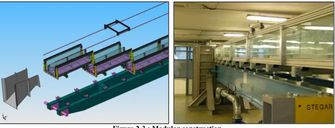
The choice to divide the whole length into 6 equal modules 1,8 m length was driven by structural and economy considerations.
Figure 2-3 : Modular construction
Figures 4 and 5 show the structure of the basic module. The longitudinal structure is composed with commercial high quality extruded beams, whose front ends are machined with precision threaded holes and reference pin holes in order to be connected to the front flanges. The integration is to be performed on a reference precision fixture. A sheet of AISI316 stainless steel is posed on the longitudinal beams, to which is connected and sealed by way of special fittings.
The side walls are made with composite sheets of glass and polycarbonate; walls and bottom constitutes the channel element which is ended by two flanges. Between composing elements a net of sealing o-ring like cords are foreseen. The end flanges are built up in three plates which are mechanically referenced and machined when assembled. They are equipped with reference holes and sealing grooves in order to allow a proper coupling with the next channel element.
Figure 4-5: Basic module
When screwing together the flanges a slight pivoting around coupling pins is allowed, so to guarantee a perfect alignment between a module and the other is guaranteed. Some slight pivoting can be operated also after the integration is over, so to allow a further control of the overall alignment.
In the module’s top part there are two aluminium profiles with double section respect to the bottom ones, with a double purpose: to strengthen the module’s structure and to act as a support to the rails for the probes chariot. The rails run continuously along the whole length of the “channel”.
Figure 6-7: Running chariot
In image 5 the components to reduce the water accessible section is also visible; it is constituted by a glass panel with rubber sealing, with three stirrups for every module. These supports are settable through opportune holes in the closing flanges; when they are not used the holes are masked with flat headed screws.
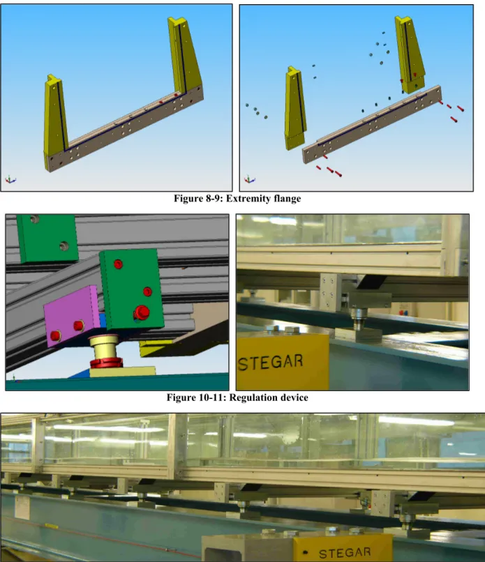
Like previously pointed out, the extremity flanges are built in three separate pieces, to avoid the material waste that would be caused by an ex-block machining.
In images 8 and 9 configuration of the modular element’s extremity flange can be appreciated. In the exploded view the outline of the elements and connections can be seen.
Some connection and regulation elements between the modules themselves and the supporting beam are shown in the following.
Such regulation elements concur to the alignment of the modules in terms of planarity and linearity, etc, and may be useful to recover such parameters in case of deformations or yieldings of the structure.
In figures 10-13 the base element of the regulation system can be seen, it is interposed between the carrying structure of carpentry and the modules that compose the “channel”. Every module is supported by 4 identical elements.
The vertical regulation is entrusted to four large section fine pitched screws with locking device. The cross-sectional regulation is executed with two simple screw systems.
The probes chariot is aluminium made (fig 6-7). It rides on four wheels, two of which are adjustable through an eccentric mechanism. The wagon can be blocked through an hand operated clutch.
At the water outlet towards the lower tank, a collector has been inserted properly shaped in order to avoid turbulence, spraying, counterpressure or other phenomena which may cause disturbance to the experiment. A
special care has been devoted to define the shape of the collector, especially in order to fit the varying geometry of the connection when varying the slope.
Figure 8-9: Extremity flange
Figure 10-11: Regulation device
Figure 12: Serie of regulation devices GENERAL DESCRIPTION
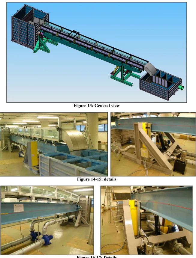
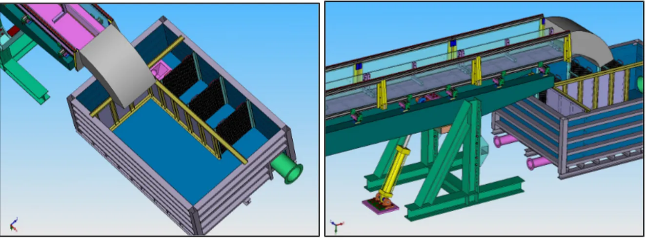
Figure 13-17 show the overall sight of the integrated facility and some details. They are respectively a CAD model and some photographs. We can observe upper and lower tanks, the “channel” with its support beam, the rails with the probes chariot, the main support with hinge connections, the secondary support with slope regulation jack, lower tank and connection elements.
In figures 18-19 some insights of the mount tank. The tank is divided into two volumes, with a complex hydraulic connection aimed to calm down any turbulence before inletting the channel.
Figure 13: General view
Figure 14-15: details
Figure 16-17: Details
The tank has a relevant height aimed to take profit of the hydraulic head to help dissipating the kinetic energy of the water coming from piping. The wall dividing the tank into two volumes is aimed to separate the zone of breaking in of the pumps from the zone devoted to the laminar flow.
On the bottom of the tank a battery of about 50 tubes, 50mm in diameter, connect the volume of turbulence to the volume of laminar flow. The length of the tubes decreases from bottom to top, helping the water to assume an ascending attitude. In fact this lay-out has been studied so that the water escaping from the aforesaid tubes is directed upwards from the walls or the surrounding fluid veins.
The desired effect consists in the fact that the “laminated” part of the tanks must have a behaviour similar to a "lake", that is to say that it must approximate what in hydraulics science is defined as "infinite capacity tank".
So it turns to be very important the dimensions of the tank and also the laminating effect, to obtain a “flywheel-damper” effect on the oscillation of the conditions of the entrance of the “channel”.
Figure 18-19: Upper tank with laminating device
Figura 20-21: Upper tank details
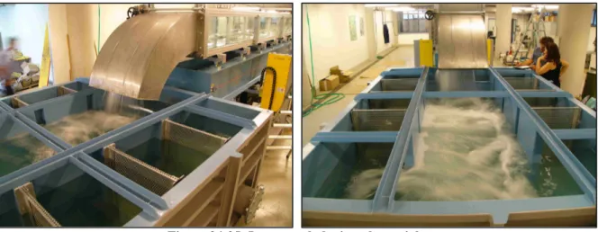
Notice the stationary wave generated in a running test. The stability of the phenomena is helped by the laminar situation at inlet level. An entrance patch guides the fluid vein towards the “channel” avoiding any vortex generating cause in order to respect condition of ideal admission with zero loss coefficient. The shape of such patch varies according to a particular curve to maintain ideal conditions. The patch is linked directly to the moving section of the channel, a rubber fitting allowing the relative displacement.
The lower tank receives the water flux from the channel (fig 22-25). The receiving volume must be as large as possible to reduce turbulences. Then the water turns 180° and passes through a battery of laminating bulkheads which filtrate the flow and stop possible debris.
The design of the lower tank has achieved a balance between contrasting needs: to reduce dimensions to handle it during assembly phase, to have a volume to effect as a “water flywheel” similar to that of the upper tank, to be not too tall not to interfere with the slope variation of the channel, to guarantee a water head of 700-800 mm minimum to avoid pump cavitation. The tank has also a secondary outlet to lead water to the buried tank, if necessary.
Figure 24-25: Lower tank during plant trials CONSIDERATION ON DRAWING AND TOLERANCES
The facility has been developed and designed inside the group of "Mechanical Design" of the Faculty of Engineering of the University of the Studies of Brescia.
The "channel" in object is not properly a machine, in the sense that its characterizing aspects are more structural than mechanical. Neither relevant motion nor transmission of power is involved, but the requirements refer to the ability to guarantee precise geometric relations between its components. Nevertheless the necessity to achieve high precision standard and precise geometry variations has suggested a mechanical approach instead of a structural one.
The characterizing peculiarity of these machines is the possibility to have an infinitely variable range of settings in order to answer to varied environmental changes.
In fact, the sense of all this complex project lays in the demand for being able to operate in the conditions requested in terms of dimensional and geometric during the load and operation variations or bring back in tolerance the entire structure during some event’s taking place.
Moreover mechanics has to be responsible for the modules’ reciprocal alignment and to overtake all the structural weaknesses of unusual structural materials such as glass.
In part we moved from machine field to structure field, nevertheless morphological conditions and precision needs make this project more similar to a machine project than to a structural project.
It is possible to say that the term “machine” is more appropriate for the series of operation during the assembly and regulation phase than after, during normal operations.
REFERENCES
[1] ISO 14660-1, “Geometrical product specifications (GPS) -- Geometrical features -- Part 1: General terms and definitions”, ISO, 1999
[2] ISO TR 14638, “Geometrical product specification (GPS) – Masterplan”, ISO
[3] Cambiaghi D., Cambiaghi A.: Design environment (space). Complementary use of modeling and testing
phases. Nuclear instruments e methods in physics research - Vol.522 – April11,2004 – ELSAVIER
[4] UNI CEI ENV 13005, “Guida all’espressione dell’incertezza di misura”, UNI, 2000 [5] UNI 4546, “Misure e misurazioni – termini e definizioni fondamentali”, UNI, 1984
Malagola G., Ponterio A.: La metrologia dimensionale per l’industria meccanica, Augusta ed., 2004 [6] Chirone E., Tornincasa S.: Disegno Tecnico Industriale Voll 1 e 2, Il Capitello, Torino