UNIVERSIT`
A DEGLI STUDI DI CATANIA
Facolt`
a di Scienze Matematiche Fisiche e Naturali
Dottorato di ricerca in Informatica
ENFORCING TRUST, COLLABORATION AND
POWER-SAVING IN MANETS
GIANPIERO COSTANTINO
A dissertation submitted to the Department of Mathematics and Computer Sci-ence and the committee on graduate studies of University of Catania, in fulfill-ment of the requirefulfill-ments for the degree of doctorate in computer science.
ADVISOR Prof. Salvatore Riccobene
COORDINATOR Prof. Cantone Domenico
i
Printed December 2010
This opera is licensed under a
Abstract
Nowadays mobile data communications are becoming more and more popular and, at same time, people routinely carry along the last generation of mobile devices, called Smartphones. In particular, the ability to connect directly to other similar devices makes smartphones very powerful.
The field that we are going to explore is that of Mobile Ad hoc Networks (MANETs). In a network without infrastructure, devices are connected di-rectly or by means of others and this makes collaboration fundamental even though the behaviour, that is, the collaborative attitude of each participant. To provide a more transparent system, we present a mechanism in which a device, through observation of a neighbour, is able to establish the reputation of that neighbour. Afterwards, that value for each node is scattered across the network by means of special packets called Recommendations.
Values of reputation obtained with the previous mechanism are parame-ters of judgement for a Quality of Service (QoS) technique used in communi-cations. Indeed, devices with a bad reputation are strongly penalised when they require a service to others. In particular, the penalisation that a node gets depends on its contribution of collaboration: the less is the collaboration the more is the penalisation.
iii
Finally, we focus our research on power-saving. By introducing a novel protocol to cover a weakness of the Dynamic Source Routing (DSR), each device becomes capable of preserving its own energy especially during long and repetitive communications.
All prototypes designed in this thesis were implemented and simulated through the Network Simulator 2 (NS2).
Acknowledgements
I would like to thank my two advisors: the official one, Salvatore Riccobene, and the unofficial one, Giampaolo Bella. They taught me a lot with their experience throughout these three years of Ph.D. In particular, many thanks to my Professor because he gave me important suggestions regarding the hard life of a Ph.D. student, as a father makes with his son. On the other hand, Giampaolo has been for me a person often strict and meticulous, but fundamental for my career.
I would like to thank my external advisor at the University of Cam-bridge, Jon Crowcroft. I was a visitor for four months at the most important European University and Jon gave me the possibility to have an amazing experience there, both of research and human life.
I would like to thank my friends, my colleagues, Teresa and all the people close to me for spending with me important moments during my Ph.D.
Finally, but with the same importance, I would like to thank my family and in particular, my parents who sustained me throughout my eight years of University.
Contents
1 Introduction 1
2 MANETs 6
2.1 Main features of a MANET . . . 7
2.2 Main features of a device . . . 8
2.3 Taxonomy of Routing Protocols . . . 9
2.3.1 Flat Routing . . . 10
2.3.2 Hierarchical Routing . . . 11
2.3.3 Geographic Position Assisted Routing . . . 12
2.4 Survey of MANET’ Routing Protocols . . . 12
2.4.1 Flat Routing . . . 13
2.4.2 Hierarchical Routing . . . 16
2.4.3 Geographic Position Assisted Routing . . . 17
2.5 MANETs like P2Ps? . . . 20
3 Dynamic Source Routing 23 3.1 Route Discovery . . . 24
3.1.1 Route Request . . . 24
CONTENTS vi 3.1.2 Route Replay . . . 25 3.2 Route Maintenance . . . 25 4 Network Simulator 2 27 4.1 How NS2 works . . . 28 4.2 The structure of NS2 . . . 30 4.3 Wireless networking in NS2 . . . 34
5 How to establish the reputation of nodes 43 5.1 The Proposed Protocol . . . 47
5.1.1 Reputation by Direct Observation . . . 47
5.1.2 The Global Reputation Table . . . 53
5.1.3 Reputation Table Exchange . . . 53
5.1.4 How to estimate the Global Reputation . . . 56
5.2 Simulation and Performance Evaluation . . . 60
5.2.1 An observed good behaviour . . . 62
5.2.2 An observed bad behaviour . . . 63
5.2.3 Joining the network . . . 64
5.2.4 Uniformity of reputation value . . . 66
5.2.5 Working of the Old-Age Function . . . 66
6 Enforcing collaboration with a QoS technique 68 6.1 Optimising the nodes’ use of energy . . . 71
6.1.1 Analysis on consuming during forwarding . . . 71
6.1.2 Consideration about lifetime . . . 73
CONTENTS vii
6.2 Simulations . . . 78
6.2.1 QoS: collaboration or not? . . . 81
7 Extending nodes’ lifetime 83 7.1 DSR and Shortest Path First . . . 87
7.2 Dynamic Path Switching . . . 89
7.2.1 Managing energy warning situations . . . 90
7.2.2 How to perform the request . . . 92
7.2.3 Managing the request . . . 94
7.2.4 Changing state or not . . . 96
7.3 Simulations . . . 97
7.3.1 SPF vs DPS . . . 98
Chapter 1
Introduction
Back at the beginning of this century, when people spoke about mobile phones, what they had in mind were devices with standard features such as calling or sending text messages in mobility. At that time, purchase preferences were mainly driven by the exterior design of products. Then, companies introduced new features such as bluetooth communication [1] and a camera to take and share pictures directly with a mobile phone. Feature integration was the trend of the market of mobile devices until companies presented the Smartphone. According to the webpage of Wikipedia: [2] a smartphone is a mobile phone that offers more advanced computing ability and connectivity than a basic ”feature phone”. While some feature phones are able to run simple applications based on generic platforms...
This definition explains clearly that this new generation of devices is an evolution of the traditional ones. This is provided by the possibility to get connectivity with the Internet or other smartphones and to install applications. In particular, those may be very complicated.
1 Introduction 2
The fully-fledged Operating System (OS) makes a smartphone very pow-erful. The OS of recent smartphones are particularly similar to the OS of a computer. Their functionalities are very similar even though they have differ-ent constraints. While the first generation of mobile-OSs were very limited, today, instead, they allow their users to perform mobile browsing, emailing and so on. In addition, it is possible to download new applications from an endless list of softwares to add new functionalities to the original OS. That is the reason why in the last years people are getting used to buying and using smartphones instead of traditional phones.
It is also true that a smartphone is typically less powerful than current personal computers, hence carrying out all tasks that are normally done in a desktop or laptop may not be possible to do. Although this is potentially feasible, smartphones are constrained by computational power and battery life. This latter is a severe limitation of smartphones. Indeed, applications require a huge use of the processor with consequent significant battery con-sumption. The more intensively a processor runs, the faster it consumes energy. Therefore, companies such as Apple [3] for a few years limited the number of applications that are running in multitasking in order to save energy. Moreover, depletion of energy does not depend only on processor activity but also on communication workload. For this reason a user must prevent an excessive consumption of the battery due to his usage.
Nowadays, people are tempted to buy a smartphone rather than a tra-ditional mobile phone at least because the latter offers more functionalities. People can easily create a network with their smartphones in order to ex-change data. The size of the network can be formed depends upon the
com-1 Introduction 3
munication technology used. For example, a bluetooth device cannot reach the same distances as a Wi-Fi one. This is due to hardware limitations. Either technology allows creation of an Ad-Hoc network. In particular, an Ad-Hoc network is characterised by the lack of a central infrastructure, so that the users are connected directly. In case of devices, called also nodes, that are not reachable because they are too far away, other mobile phones are used to forward messages to a destination. This network is called Mo-bile Ad hoc Network (MANET), and its participants can only be moMo-bile devices. Mobility is the peculiarity of MANETs with respect to other types of networks.
In order to make sure that a MANET runs properly, those users that are in that network, must take a fair behaviour. Fairness here means that each device should collaborate to the networks survival. The reason why this is very important is the limitations of the devices, which were outlined above. As already noted a user cannot reach all other devices directly or in one hop but others have to help forward the message. Since nothing enforces that collaboration, a device could decide to avoid collaboration and as a consequence the network may not work in the right way.
With the motivation of thwarting the fragility of MANETs just outlined, we decided to study these networks both macroscopically, that is holistically, and microscopically, that is terms of behaviour of each participating devices. Moreover, we want to highlight that the research fields considered in this thesis are split into three different branches:
1 Introduction 4
• Collaboration; • Power-saving.
All those research fields represent our fully-fledged work seen as different “bricks” and by merging all points, we provide a sound product ables to prevent and reduce selfishness, combined to energy saving for MANETs.
We are particularly interested in observing the reputation of the par-ticipating nodes. This parameter indicates how much a node is willing to collaborate in keeping the network. Although the willingness to collaborate of each node cannot be precisely known to its neighbours, this may obtain a good estimate by calculating the reputation of the node. In this vein, we will introduce a metrics for the reputation of all participants of an Ad-Hoc network.
However, the goals of this thesis are yet more complex and ambitious. It was already remarked that collaboration is crucial to MANETs. Therefore we aim at increasing the collaboration of the participating nodes as much as possible. In a rational prospective, a node collaborates only if it earns something. In particular, using an approach similar to that used in P2P networks — fully described later — we show a protocol that, through a Quality of Service (QoS) technique pushes nodes to collaborate.
Intuitively, a node that behaves selfishly will be somehow penalised. The obvious way to penalise a node in a network is to delay the traffic that the node generates. By contracts, a node can prevent such a penalisation by being collaborative, in such a way that its generated traffic will not undergo any delay.
1 Introduction 5
So, by introducing QoS during communications, we want to show that collaboration can be increased. The intuition is that a node tends to collabo-rate in order to avoid a low quality service. In Chapter (6), we show our idea of QoS adapted for MANETs. Also, we provide some simulations in which QoS is used by all participants of the network.
Finally, we focus our work on power-saving. As mentioned above, the battery constrained of mobile nodes is crucial. It is impossible to build an infinite battery, so our aim is a mechanism to reduce the wasting of energy. In particular, our approach takes advantage of a weakness of the routing protocol. As we describe later, although nodes keep the ability to reduce their collaboration to preserve energy, they will be guaranties that the network remains alive. This strategy can be implemented together with the intelligent routing strategy mentioned earlier. We have tested them through simulations and we will describe our findings. For example, we shall see that a node with role of forwarder can preserve a lot of energy.
This thesis is organised in the following way: Chapter (2) introduces in a deep way MANETs and, also we give a survey of the most important routing protocols. Then (Ch.3) we provide to the reader an overview of the key features of the Dynamic Source Routing protocol. After that, we present the Network Simulator 2 (Ch.4), its way of working and its wireless section. In Chapter (5) the topic regarding reputation is introduced and argued. Afterward, we present our mechanism to push collaboration (Ch.6) through a Quality of Service technique. Finally, we tackle the power-saving issue (Ch.7) and we conclude this thesis with Chapter(8).
Chapter 2
MANETs
A Mobile Ad hoc network is characterised by the presence of wireless devices that are connected each other without a prefixed-infrastructure. The main feature of this network is the lack of particular structural devices and this makes MANETs and P2Ps belonged to under the same branch. On the other hand devices, such as routers, switches and so on, make wireless ad hoc network very different from the wired one. In the latter case, a participant can feel free to send a packet to the network because when a packet reaches a router, this is able to route it in the right way.
Since in a MANET devices have to perform different tasks, such as rout-ing, collaboration between participants is fundamental. However, a device not alway gives its availability to collaborate and this could be dangerous for a network in terms of reachable nodes. One of the main causes of this selfishness is to save energy’s node since it is a limited resource.
In the past a MANET was mainly used for military aims. The possibility to realise a wireless network without external supports, like radio-bridge,
2.1 Main features of a MANET 7
made this technology very suitable for the previous field. Indeed, each soldier, which carries his own mobile device, could be able to reach another teammate in a easy way.
Nowadays, the presence of mobile devices is becoming more and more popular. This allows people, which are using their devices, like a smartphone or PDA (Personal Digital Assistant), to create a network instantly. All these handsets are equipped with one or more wireless resources. So, people who are in a public place are able to realise a network without any additional charge.
2.1
Main features of a MANET
As we said before, MANETs and P2Ps are very similar and a fair behaviour represents a fundamental aspect of both network. In particular, sharing of resources by nodes is needed to provide an efficient net.
S
A
B
D
C
E
F
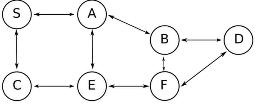
Figure 2.1: Example of a wireless network
In fig.2.1 is shown a MANET composed by some nodes. They are able to communicate each other and this can be done directly or through other
2.2 Main features of a device 8
devices. Due to its transmission range, the sender “S” cannot reach in one-hop the receipt “D”, so it has to ask its neighbours to forward the message. The request of collaboration can be performed only if others share their resources, but on the other point of view, a forwarder pays something in terms of resources during the sharing. According to this, not always a node wants to forward data for others and this way to behave as selfish could be very dangerous for a MANET.
Another feature mentioned before is the lack of a prefixed infrastructure. The latter can be classified as the biggest difference between traditional ca-bled networks and ad hoc wireless ones. In the first one, a node performs only the role either of sender or of receiver. In particular, when it wants send a message, it uses just a gateway node, such as a router. Instead, since in a MANET devices run the same role, they have to forward data for others.
Mobility is an important characteristic of a wireless network and it makes the topology of a network very dynamic. In particular, this feature requires that the routing protocol used in MANETs must be as reliable as possible. According to this protocols that build paths on-demand are proposed.
2.2
Main features of a device
A node of a MANET is characterised by its light weight. That is why smart-phones nowadays are perfect candidates to take part in this network, even though they have a limited lifetime due to their battery. Sending and re-ceiving information are activities in which a node can waste a lot of energy. Especially, when a node is running out of energy it could decide to stop
2.3 Taxonomy of Routing Protocols 9
collaborating in order to save the remain lifetime.
Short-coverage range is the reason why a node needs collaboration of others. Today a traditional smartphone can cover a transmission range for one-two hundred meters and only close devices can be reached. Also, a com-munication range depends on the position of a node. For example, an indoor communication is more limited because of walls that can reduce drastically the transmission. Instead, when a network is built in a free space, this can allow participants to cover a larger area.
From the security point of view, a device should adopt a cryptographic layer during communications since wireless traffic can be easily “observed”. In spite of this, a cryptographic layer to add to a MANET cannot be high because low computation processor embedded in each device could not be able to perform heavy operations. That is why in the majority of situations a message is sent unencrypted.
2.3
Taxonomy of Routing Protocols
As we said before a MANET is composed only by nodes that accomplish a same role. Routing of messages is not done by routers but devices have to discover paths. In literature are presents different routing protocols that are classified in: Flat Routing, Hierarchical Routing and Geographic Position Assisted Routing.
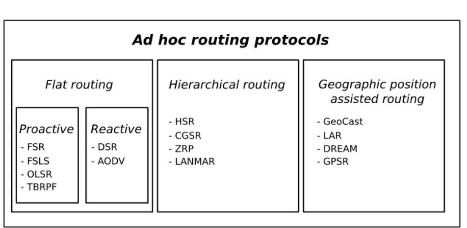
Following in fig.2.2 we show the complete classification of all routing protocols:
2.3 Taxonomy of Routing Protocols 10
Ad hoc routing protocols
Flat routing Hierarchical routing Geographic position assisted routing Proactive Reactive - DSR - AODV - FSR - FSLS - OLSR - TBRPF - HSR - CGSR - ZRP - LANMAR - GeoCast - LAR - DREAM - GPSR
Figure 2.2: Classification of Ad hoc routing protocols
2.3.1
Flat Routing
In this set of protocols all nodes are part of the same hierarchical level. Indeed, a message can be broadcasted towards others without following a particular pattern.
Proactive
As part of flat routing protocols the proactive ones are characterised by the presence of routing tables inside each node. Each node of a network contains a table with the majority of paths already known. When a device wants to send a message in a quick fashion, it searches the path for a receipt inside its own local table. As disadvantage, each node must update regularly its own table in oder to obtain reliable paths. This happens through tables exchange between nodes and, when a participant receives a new update it must replace its own older data with the newer ones.
2.3 Taxonomy of Routing Protocols 11
Reactive
On the contrary these protocols adopt a different approach. A node does not know a priori the route to follow to reach another device. When this happens it must discover the right path in real time. Using a special routine, called Route Discovery, a node is able to discover the most reliable path. According to this a device knows only paths that it needs.
Benefits of these protocols is the possibility to get the most updated path because mobility is very frequent. That is the reason why recently this branch of protocols are privileged respect to the proactive ones.
2.3.2
Hierarchical Routing
Although a MANET is composed by a limited number of devices, scalability of the participants must be guarantee. To prevent problems of overloaded links a routing protocol must be able to overcome this threat. Due to this factor, hierarchical routing is more suitable. The main idea of these protocols is to split all set of nodes into clusters and, each group keeps a leader, called clusterhead. When a node wants to communicate with another device out of the cluster, it must pass through the clusterhead.
Using this approach a node can contain a reduced number of items inside its own routing table. Indeed, it has to know only links towards its clus-terhead. Moreover, this idea decrease the amount of maintenance data that travels across the net.
2.4 Survey of MANET’ Routing Protocols 12
2.3.3
Geographic Position Assisted Routing
Nowadays, majority of smartphone are equipped with a Global Positioning System (GPS), that is very cheap and small. Also, today precision to locate a device is becoming more and more accurate.
Since, a GPS is used to find the location of a node, geographic position assisted protocols manage this information to discover paths in a quick man-ner. By knowing the position of receipt, a sender is able to select a priori which nodes must forward the packet. Moreover, due to high mobility of de-vices, positions of them must be often updated. However, this strategy could overload a network since participants must exchange their new positions.
On the other hand a node can keep its table very light. This because they don’t need to save routes in their tables. According to this GPAR protocols are suitable for sensor network. Indeed, within this environment devices are characterised by the presence of weak resources.
2.4
Survey of MANET’ Routing Protocols
During these years researchers developed different routing protocols for MANETs. In this section we are going to present the most important routing protocols that can be used throughout communications. In particular, we decided to argue only one for each family in a deep way and for a detailed description of others, we refer the reader to the original papers.
2.4 Survey of MANET’ Routing Protocols 13
2.4.1
Flat Routing
Following the list of protocols that are part of proactive family.
Proactive Routing Protocols • Fisheye State Routing (FSR) [4]
• Optimized Link State Routing Protocol (OSLR) [5]
• Topology Broadcast Based on Reverse Path Forwarding (TBRPF) [6]
Optimized Link State Routing Protocol
Since a path is not obtained on-demand each node must discover all in-terested paths before starting a communication. This is done in the following way: first of all through a HELLO message a node explores its neighbour-hood and it is sent in a broadcast way towards all neighbours. In particular, an HELLO message contains a list of paths already known. When a node receives the message, it just stores the information contained without for-warding the packet. All data obtained from an HELLO message are kept only for a limited period beacuse mobility of nodes pushes them to refresh their neighbourhood frequently.
Messages to find neighbours are sent in a flooding manner. This technique could be counterproductive but in order to limit it, OLSR uses a mechanisms, which is explained in [7], that reduce the problem. Moreover, when nodes receive data regarding the topology of a network, they are able to keep this information in order to store available routes. After that, a node uses the Shortest Path First SPF strategy to select a path.
2.4 Survey of MANET’ Routing Protocols 14
Reactive Routing Protocols
Following the most important reactive protocols are listed: • Dynamic Source Routing (DSR) [8]
• Ad hoc On-Demand Distance Vector Routing (AODV) [9]
Dynamic Source Routing
This protocol is deeply used for the aim of this thesis and for this reason why we preferred to dedicate Chapter (3) for the whole description.
Ad hoc On-Demand Distance Vector Routing
AODV was realised in order to obtain a routing as light as possible. Ac-cording to this a node is used to keeping a table with just the most used links. In particular, a device disowns a route until it does not run the proce-dure to discover a path for a destination node. The latter proceproce-dure is done by means a Route Request (RREQ). A RREQ packet contains the following fields:
• Source: address of a sender;
• Source-Sequence: list of nodes that forward the RREQ; • Destination: address of a destination;
• Hop-Counter : counter of hops;
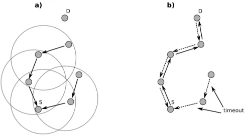
When a node receives a RREQ, it forwards the request to its neighbours adding the reference of the previous forwarder into the packet. This process is called Revers Path Setup and it is represented in fig.2.3a. However, this
2.4 Survey of MANET’ Routing Protocols 15
information is kept just for a shot period but enough to create a reply message to the source. D S a) S b) D timeout
Figure 2.3: Reverse (fig.a) and forward path (fig.b) in AODV
If a forwarder, during a RREQ forwarding, knows the path to reach a destination, it uses this information to build the whole route. After that, it creates a Route Replay (RREP) and sends back this packet with the path discovered. In particular, the RREP travels through the route found by Revers Path Setup process, fig.2.3b.
When the sender receives a RREP, it extrapolates the path from the packet. According to this the route obtained is used by the sender to reach the receipt. However, the new path got by the source node is valid only for a period. Indeed, if its lifetime is not updated the path will be removed from the cache table of the node.
As we said before, AODV is a reactive protocol, this allows nodes to keep light routing table storing only minimal information regarding to paths.
2.4 Survey of MANET’ Routing Protocols 16
Another characteristics of the routing protocol is the lack of periodical messages. Adopting this feature the protocol avoid to overload a network with maintenance data.
2.4.2
Hierarchical Routing
The following protocols adopt the hierarchical approach to route information in a MANET:
• Clusterhead Gateway Switch Routing (CGSR) • Hierarchical State Routing (HSR) [10]
• Landmark Ad-hoc Routing Protocol (LANMAR) [11]
Clusterhead Gateway Switch Routing
This protocol uses the clustering algorithm called Least Clusterhead Change (LCC). The latter one is used to split a network into different clusters. Inside each cluster a clusterhead is elected. If a node can be reached by a cluster-head, it belongs to clusterhead’s cluster. In particular, whether a node is covered by two clusterheads it assumes the role of gateway.
When a clusterhead changes its cluster, it could lose its role. Indeed, it is impossible that two clusterheads ”live” inside the same cluster. According to this one of them must lost its role. So, the clusterhead with the bigger numbers of active links belonged to it can become the only clusterhead
CGWR adopts the distant vector routing DV algorithm. For routing a packet each node has two tables. The first one contains the clusterhead of
2.4 Survey of MANET’ Routing Protocols 17
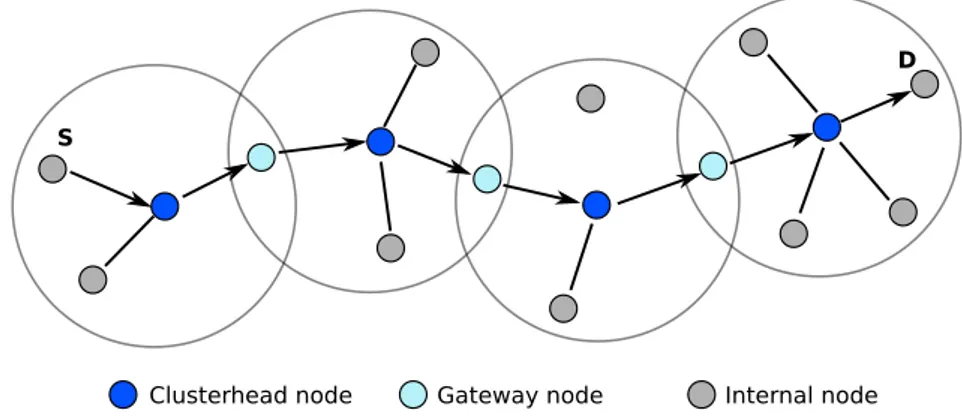
each destination node. Instead, the other one reveals to a node the right path to reach a cluster. When a node wants to send a packet to a destination one, it looks for the clusterhead of a destination node. After that, it sends the packet to its clusterhead. Then, the latter one forwards the packet to the gateway that know how to reach the destination’s clusterhead. However, it is possible that the packet must pass through other clusters before reaching the destination. In fig.2.4 is shown an example of packet forwarding until a destination node.
S
D
Clusterhead node Gateway node Internal node
Figure 2.4: Forwarding of a packet using CGSR
2.4.3
Geographic Position Assisted Routing
Below routing protocols that use a GPS device to discover node’s position are listed:
• Distance Routing Effect Algorithm for Mobility (DREAM) [12] • Geographic Addressing and Routing (GeoCast) [13]
2.4 Survey of MANET’ Routing Protocols 18
• Greedy Perimeter Stateless Routing (GPRS) [15]
Distance Routing Effect Algorithm for Mobility
DREAM is a proactive protocol and it uses a node’s position to route information. Each node contains a table in order to store the position of others. So that information about position of nodes are accurate, a partici-pant must send its update position periodically. In particular, the bigger is mobility, the more frequent is sent an update message of a node’s position.
This protocol adopts special features to refresh the localisation of a device. Indeed, a participant prefers to send an accurate position to close nodes because a device is less interested in a accurate information of far away nodes. This idea was implemented to reduce the cost due to the information exchange across the network.
C
A
C
B
B
Figure 2.5: Inserire caption con il nome dell’effetto
To explain better the concept, in fig.2.5 are shown three nodes. Node B and Node C are moving in the same way. In particular, Node C is farer to Node A respect to Node B. It is possible to observe that the movement of Node C looks like ”less important” of the other one. Indeed, from the point
2.4 Survey of MANET’ Routing Protocols 19
of view of Node A the degree of movement of Node C seems lower of Node B one. Due to this phenomenon Node A can recognise the position change of Node C even though the latter one provides an information less accurate.
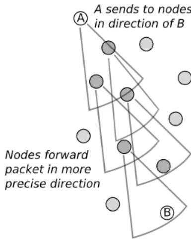
A B A sends to nodes in direction of B Nodes forward packet in more precise direction
Figure 2.6: Partial flooding in DREAM
When a node collected all localisation positions of others, it is able to start to send a message using a partial flooding, fig.2.6.
A sender selects a number of neighbours that are in the same direction of the destination node. Nodes selected by a sender are added in the header of the message. In this way, when one-hop neighbour receives the message, it will forward the latter one only if it is present in the header, otherwise the device will discard it. Each forwarder will repeat the same procedure done by the sender. Following this idea the message is delivered to the destination. In case that a forwarder does not find any neighbours in the same direction of the receipt, it will forward the message using a flooding.
2.5 MANETs like P2Ps? 20
2.5
MANETs like P2Ps?
P2P networks and MANETs can be considered very close each other because they need collaboration for working. In particular, a P2P is a distributed network composed only by participants that share resources. Respect to the client-server paradigm, where only a server provides information, in P2P net-works all devices can provide something in terms of resources; these usually are, memories, CPUs or just documents. Moreover, the P2P topology respect to the client-server one avoids that nodes overload the provider, i.e. a single server. This feature makes P2P networks more scalable respect to the older paradigm.
Nowadays, P2P networks are used especially for sharing of documents. The first P2P software developed was Napster [16], it was developed to share music files, like mp3 [17] but its life was not easy since sharing of mp3 was illegal. Indeed, people was able to get music without paying and this phe-nomenon is, clearly, not allowed.
Working of Napster was very easy: a user could share its files to the com-munity or it could search other music files using different keywords. Doing so a list of downloaded files was available and a peer was able to download the desired file using the P2P protocol.
It is clear that this mechanism cannot be legal and as consequence the life of Napster was short. In fact, the application was closed but at the same time other P2P applications were developed. After some years, Napster was re-open but as a online music store, and today people are able to buy music legally using the same software.
2.5 MANETs like P2Ps? 21
Nevertheless, after Napster a lot of other P2P protocols were born. The most famous are Kazaa [18], Gnutella [19], FastTrack [20], FreeNet [21], Skype [22, 23], Bittorrent [24], Emule [25] and so on. All these listed protocols are different each other although they belong all within the P2P family. Respect to Napster, the others are more complete softwares. These allow peers to share a huge quantity of documents, such as movies, musics, books etc, but as it happened for Napster all of them are often blamed to allow illegal download of files.
On the other hand, these applications can be seen as a very easy way to share resources. Indeed, shared files can be legal and companies often use P2P protocols to provide a faster download of free software. This is a perfect alternative to the client-server paradigm that could make a company’s server overloaded easily denying to get the files to others.
Main strength of P2P networks is the collaboration and peers sharing their files allows the network to work properly. In order to reduce the situa-tion in which users would avoid collaborasitua-tion, P2P protocols adopts mecha-nisms to push peers to collaborate. For example, Emule introduced a system that works using credits. Indeed each user keeps an amount of credits that increase when a peer uploads any type of file. Doing so, the user is able to get a faster download spending its own credit acquired previously.
When peers discovered that just sharing files their obtained credit, dishon-est users decided to share documents with false names. Using this approach a peer who downloads, got a fake document, whereas a peer who uploads, got credit wrongly. This is a strong weaknesses of that protocol and to tackle that problem, Bittorrent decided to use a different approach. The main
dif-2.5 MANETs like P2Ps? 22
ference is that when a peer earns credits from another one, it can spend the credits acquired only with that peer. In this way, a user has less interest to share fake files since it cannot re-spend the credit acquired with others. The idea used by Bittorrent got very success and nowadays the latter protocol is becoming more and more used.
In the last years, P2P protocols are not used just for sharing of docu-ments. Skype, which is the application that allows people to call each other using Voice Over IP (VOIP) [26], uses a P2P strategy to link peers. Today, this application is often used and peers are able to call both landline and mobile numbers in a very cheap price. Since Skype is a P2P network, it does not use a server to keep peers’ information. Moreover, all data exchanged be-tween peers are encrypted and the algorithm used to encrypt is the Advanced Encryption Standard (AES) [27].
Although MANETs and P2Ps share some aspects, like collaboration and lack of a fixed infrastructure, they have been developed for different aims. MANETs were thought for small-medium networks, where devices create links of communication and these last for a short time. Then, participants are mobile users constrained by their own battery.
On the other hand, P2Ps manage a large number of peers who are con-nected each other to exchange an huge amount of data. Here, users can use different machines to connect to a network, such as desktops, laptops and so on. Moreover, they do not have the battery limitation and this allows a P2P network to persist for long time.
Chapter 3
Dynamic Source Routing
Given the frequency of node mobility, it is important to keep routing tables updated and Flat Routing protocols of MANETs fall into two families. The first are proactive protocols, which use a table-driven approach to establish paths and the reliability of routing paths depends on how frequently tables are refreshed. If this is done too often, control traffic can overload connection links. To overcome this problem reactive protocols are often used to manage the routing. These protocols build paths on-demand and Dynamic Source Routing (DSR) is one example. It employs a lighter weight route discov-ery scheme, consisting of two sub-procedures: Route Request (RREQ) and Route Replay (RREP), which are used to build a path. To manage the case when links on current routes are broken, DSR implements a separate Route Maintenance procedure.
3.1 Route Discovery 24
3.1
Route Discovery
Here we review the main features of DSR. For a complete description, we refer the reader to the original paper [8].
3.1.1
Route Request
At the start of any activity, a node does not know paths to other devices. To find out new routes it uses a special packet called Route Request (RREQ). The main structure of the packet is as follows:
• A destination node.
• An identification number (ID) of the RREQ.
When the packet is received by a neighbour, it can proceed in two different ways:
1. If it knows how to reach the destination, it will take the path from its route cache table and sends back, using a Route Replay (RREP) the whole path.
2. Otherwise, it forwards to its neighbours the packet generated by the sender appending its own address to the route record.
This two last points are repeated by each node. If this packet arrives to the receipt, the latter is able to read in the RREQ which nodes have been forwarding the request. At this point the path is established and is sent back to the sender using a RREP.
3.2 Route Maintenance 25
S
A
B
D
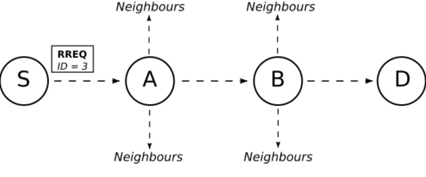
RREQ ID = 3 Neighbours Neighbours Neighbours NeighboursFigure 3.1: Path Discovering with RREQ
The fig.3.1 shows how the RREQ travels through the intermediate nodes until it reaches the destination. Moreover, the ”ID” number avoid that a node can forward a RREQ for multiple times, generating an infinite loop.
3.1.2
Route Replay
The RREP contains the path built from ”S” to ”D” and it is sent back using those nodes that forwarded the previous RREQ.
In case of unidirectional link, the destination must find an alternative path to send its RREP back. First of all, it checks other ways from its route cache table. If no alternatives are available, it will create a new route discovery for ”S”. But just in this situation it is able to piggyback the discovered path in the new RREQ.
3.2
Route Maintenance
Mobility is one of the strongest aspects of the MANETs. As consequence, links between nodes change continuously and according to this paths stored
3.2 Route Maintenance 26
in a node’s cache table must be reliable. To guarantee this point DSR uses the Route Maintenance procedure.
S
A
B
D
RERR
x
Figure 3.2: Route Maintenance with RERR
Every node is responsible to check if the link between itself and the next one is still active, e.g. in fig.3.2 Node ”A” checks for the link {A - B} and Node ”B” for {B - D}. If ”A” recognizes that there is a link problem in its link, it will wait for a maximum number of times the acknowledgement message from ”B”. If the message does not arrive, ”A” removes from its cache route table the link {A - B}. Moreover, it will spread this information using a Route Error (RERR) to the other nodes that use the same link too.
Chapter 4
Network Simulator 2
NS2 is a discrete event simulator targeted at networking research. It is of-ten used in university environments especially by researchers, students and particularity of this simulator is its development. Periodically, NS2 under-goes updates from different sources, it can be downloaded with a GNU [28] license and according to this a skilled user could realise modifications to the simulator in order to improve the product itself. Nevertheless, every change to the simulator must be approved and validated by the NS2 Committee.
Using NS2 is possible to run the majority of networking features for wired and wireless environment. NS2 has implemented all stack of network layers, from the physical to the application one and also, and to set up a simulation a user can choose different routing protocols, numbers of nodes, the type of device and other important features.
NS2 was born in the 1989 as part of the project ”REAL Network Sim-ulator” [29] and in the last years it is undergoing important modifications. Today, it is developed by different organisations: Defense Advanced Research
4.1 How NS2 works 28
Projects Agency (DARPA) [30] with the project Simulation Augmented by Measurement and Analysis of Networks (SAMAN), NFS with Collaborative Simulation for Education and Research (CONSER). Also a contribution has been given by the UCB Daedelus, CMU Monarch projects and Sun Microsys-tems for the wireless module of the simulator.
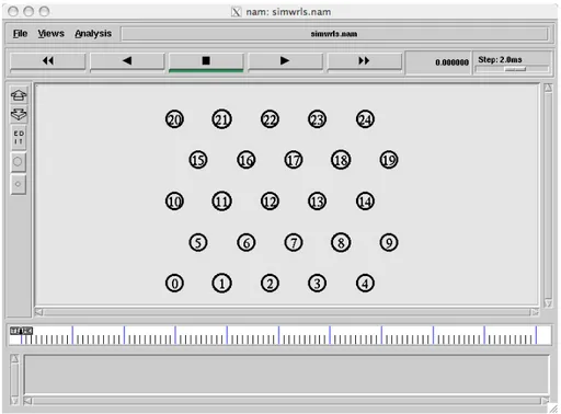
In order to perform a graphical simulation, a research can use Network Animator (NAM). It is an application that reads the output of NS2 and parsing its data traces, NAM generates graphical simulations. This allows a user to observe all devices involved in the network, their movement and when nodes send packets to others. Moreover, other features can be enabled or disabled to get an accurate observation.
4.1
How NS2 works
By far the most important feature to know about NS2 is that the simulator can be programmed using two different languages: tcl/TK and C++. The reason way developers decided to follow this mechanism is to provide more flexibility during the developing phase. A script done only with tcl/TK uses the standards modules, written in C++, already ready for NS2. Instead, when it is needed to add or realise new functionalities to the simulator a developer has to work inside the kernel, and it can be done through the knowledge of C++.
When a simulation written in OTcl is run, the script is interpreted during its execution and modifications can be done easily without recompiling all code. On the other hand, a reader should know that C++ must be compiled
4.1 How NS2 works 29
each time that a programmer makes a change and this process requires more time.
Although we said that NS2 is composed by two main languages, these two are strongly linked each other. In order to give an easy understanding how the linkage works, we introduce this example of C++ class:
c l a s s MobileNode : p u b l i c Node { [ . . . ]
}
In this case the MobileNode class inherits all the functions of the Node class and, also it implements new methods. Going through the hierarchy, the class ParentNode appears:
c l a s s ParentNode : p u b l i c T c l O b j e c t { [ . . . ]
}
This class, i.e. TclObject, is used to link the C++ and Tcl language and it is defined in the following way:
c l a s s T c l O b j e c t : p u b l i c T c l O b j e c t { [ . . . ]
v i r t u a l i n t command ( i n t a r g c , const char ∗ const ∗ a r g v ) ; void b i n d ( const char ∗ var , T r a c e d I n t ∗ v a l ) ;
[ . . . ] }
4.2 The structure of NS2 30
We consider only two functions in this part of code and they are inherited by all the classes of the hierarchy. Each time that a developer uses a OTcl method the function command is invoked.
The command to move an agent using the OTcl code is:
s e t x 1 0 ; s e t y 2 ; s e t s p e e d 5
$node ( 1 ) s e t d e s t $x $y $ s p e e d }
The method setdest is not implemented in OTcl but in C++ and ac-cording to this the system invokes the following function with argc=5 and argv={ o32, setdest, 10, 2, 3}.
MobileNode : : command ( i n t a r g c , const char ∗ const ∗ a r g v ) ; [ . . . ]
}
Inside the class MobileNode is present the method setdest that contains the implementation to move a node from a place to another within the net-work space. It is implemented using C++ and can be modified changing its source code.
4.2
The structure of NS2
4.2 The structure of NS2 31
• Event Scheduler;
• Network Component Object; • Trace.
The Event Scheduler is the component that manages all activity of the network’s objects. Every time that an object performs a new action, this is put in a data structure, such as a list or heap. An action can be a new packet generated by an application or the movement of a device. When the scheduler extracts the event from the list, the action for that event is run by the simulator. Moreover, it is possible that an event can create a new event as consequence of that. For example when an application generates a packet this travels through different layers until it goes down to the network layer.
NS2 is not able to run parallel events and if more events are scheduled in the same time, they are run in a sequential way. This is a strong weakness of the simulator since a simulation can be speeded up using multithreading technique. During our work we recognised that if NS2 had been multithread-ing we would have saved a lot of time in phase of testmultithread-ing. Especially, if a user implements a large network with a huge amount of devices and connections simulations could be long.
In order to give this feature to NS2, throughout my Ph.D. with other students and my supervisor, we tried to move NS2 into a multithreading ar-chitecture. After spending months on this work we realised that NS2 cannot be adapted to a similar architeture since all system has been created for a serial scheduling.
4.2 The structure of NS2 32
The Network Component Object is an entities that can be used as part of a network. This is either hardware or a software components, the first ones are like routers or switches, instead the latter ones can be application protocols, such as HTTP, FTP.
All components are part of a main class, then using the object paradigm they created an hierarchy of classes. Doing so, each object has different parameters that can be changed, for example the queue of a router, the speed of a mobile device or the bit rate of a communication channel.
4.2 The structure of NS2 33
The objects are split in the following way:
• Nodes (Node, MobileNode, SRNode, etc...)
• Links (SimpleLink, DelayLink, FQLink, CBQLink, etc...) • Agents (UDP, TCP, SCTP, SRM, etc...)
• Applications (FTP, HTTP, CBR, etc...)
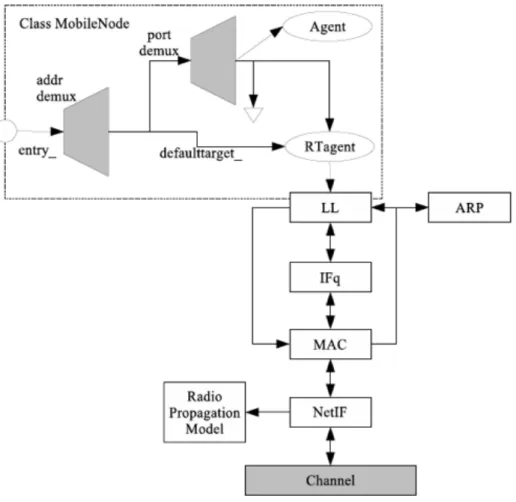
The most important network object is the class Node. It represents a device that could be a PDA, smartphone or a mobile generic object. The Node object has implemented all layers that the stack protocol needs: from the network layer to the application one. Every time that a device receives packets from its own network layer, it moves the packets towards its above layers. If the packet is not intended for it, the receiver will put the packet again in the network. This procedure is repeated until the packet does not arrive to the destination.
The last component is Trace; it is the output interface of the network and allows a user to know in a detailed way how the simulator has worked. Every time that an object creates a new event this is written in the trace file. Analysing the file a user can observe all the activity of the simulator, for example, if a FTP packet has been sent or whether a node changed its position. In particular NS2 provides three different trace files, that are used for different goals. These are:
1. NS2 trace: the simulator stores all the information concerning the net-work simulated;
4.3 Wireless networking in NS2 34
2. NAM trace: it is used by NAM. This is an application that shows in a graphic way the behaviour of the network’s objects. For example, it is possible to observe the movement of a device or a packet that travels from a node to another one.
3. CMU trace: this file is used to trace only information regarding to wireless networks.
4.3
Wireless networking in NS2
The wireless module has been introduced in 1992 as part of the CMU Monarch Project. Developers of this project decided to use the standard NS2 object adding the wireless module and this has been done implementing the wireless interface, the radio propagation module and routing protocols. Subsequently, they added features like mobility and energy consumption.
During our research work, we used only the wireless part of NS2 and according to this we chose DSR as routing protocol. In order to use that, NS2 provides a set of objects that implement the protocol.
The following code, in a tcl script, enables NS2 to use DSR:
s e t v a l ( rp ) DSR . . .
$ns node−c o n f i g −adhocRouting $ v a l ( rp ) \ . . .
The main features of DSR are implemented in the class (dsragent.c), which can be found under the subdirectory ./ns2/dsr/ . The method that we
4.3 Wireless networking in NS2 35
explored and used in a deep way is recv and it manages each packet received by a node. In particular, its signature is:
void DSRAgent : : r e c v ( Packet ∗ p a c k e t , H a n d l e r ∗ )
When a node receives a packet from the physical layer, this goes up following the protocol stacks until it is managed by the dsragent. The packet received is processed by the receiving function. In particular, it controls the packet’s content in order to decide how to handle it. For example, if a node receives a packet that is not for itself, probably it should be forwarded to another node. On the contrary if it is for the node, the packet is managed in another way. Anyway, in both cases the dsragent has been implemented to lead both situations.
Since dsragent is an open source code a researcher can modify or add some features. For example adding the following code into the dsragent::recv method a node will check the topology of the packet, if it results CBR-like, then dsragent performs a particular action.
i f ( cmh−>ptype ( ) == PT CBR) {
. . . }
Always within the receiving method, a node is able to manage a Route Error (RERR) generated by another node as it is explained in the chapter (3.2). A RERR is sent by a node as a particular packet when it wants to
4.3 Wireless networking in NS2 36
inform neighbours about one or more link broken. When the packet is made, the sender adds into the header all information required by a (RERR) packet. On the other side, when a node receive that packet, the latter one is processed inside the receiving function. In particular, the condition that triggers the function for managing that packet is the following:
i f ( . . . && s r h −>r o u t e e r r o r ( ) ) {
p r o c e s s B r o k e n R o u t e E r r o r ( p ) ; }
The method called processBrokenRouteError(p) handles the RERR and its main task is to remove from the connection’s table of the receiver the link or links that now are not available anymore.
Finally, going towards the end of the method recv after all the controls listed before, an agentDSR manages the forwarding of a packet done during a Route Request (RREQ) or a normal packet forwarding.
. . .
h a n d l e F o r w a r d i n g ( p ) ; . . .
All methods listed before have been deeply analysed during our research. Moreover, new code has been added in order to insert some relevant features for our goals.
Another model of wireless networking that we considered is the energy one. Respect to a wired device a wireless one must take into account its own
4.3 Wireless networking in NS2 37
energy and to manage this NS2 provides an energetic model. For example each time that a node sends or receives a packet its own energy decrease. In order to make that as real as possible, developers of NS2 created the object energy-model.cc.
To adopt it in a simulation a user must add the following lines of code into the TCL script:
. . .
s e t v a l ( e n e r g y m o d e l ) EnergyModel . . .
$ns node−c o n f i g
− energyModel $ v a l ( energymodel ) \
To give to the energy model more accuracy it is possible to specify other parameters, such as the initial value of energy, the energy used for sending or receiving a packet. These values can be always inserted using the TCL script. . . . s e t v a l ( rxPower ) 1 . 0 s e t v a l ( txPower ) 2 . 0 s e t v a l ( i n i t i a l e n e r g y ) 200 . . . $ns node−c o n f i g . . . − i n i t i a l E n e r g y $ v a l ( i n i t i a l e n e r g y ) \ − rxPower $ v a l ( rxPower ) \ − txPower $ v a l ( txPower ) \
4.3 Wireless networking in NS2 38
. . .
The majority of those parameters are optionals and if a user does not how to set them, then NS2 will apply the default values. However, the initialEnergy parameter is used to initialise the amount of energy (in Joule) that each node has at the begin of the simulation. Instead, the other two parameters rxPower and txPower, which are measured in Watt, express the amount of energy used for sending or receiving a packet.
Nevertheless, we want to point out that the energy model used in NS2 is quite simple. Indeed, the model misses in some aspects respect to the real way of handle the energy in a device. For example, in the simulator, when a node send or receive a packet its current value of energy is decreased only of a constant value. Instead, considering in the real case the model considers the distance between nodes too.
Going to the C++ implementation of the energy model, part of code is shown below:
void EnergyModel : : DecrTxEnergy ( double t x t i m e , double P t x ) { double dEng = P t x ∗ t x t i m e ; i f ( e n e r g y <= dEng ) e n e r g y = 0 . 0 ; e l s e e n e r g y = e n e r g y − dEng ; i f ( e n e r g y <= 0 . 0 ) God : : i n s t a n c e ()−>ComputeRoute ( ) ;
4.3 Wireless networking in NS2 39
void EnergyModel : : DecrRcvEnergy ( double r c v t i m e , double P r c v ) { double dEng = P r c v ∗ r c v t i m e ; i f ( e n e r g y <= dEng ) e n e r g y = 0 . 0 ; e l s e e n e r g y = e n e r g y − dEng ; i f ( e n e r g y <= 0 . 0 ) God : : i n s t a n c e ()−>ComputeRoute ( ) ; // T h i s v a r i a b l e k e e p s t r a c k o f t o t a l e n e r g y // c o n s u m p t i o n i n RECV mode . . e r =e r +dEng ; }
As it is possible to observe in both situations the current level of energy it is decreased of the amount of energy set before in the TCL script. It is also true that when the value of energy of a node is less than zero, it cannot send or receive any other packet.
We tested for long time this class and during the simulations we found that the following row of code is not run as it should be.
God : : i n s t a n c e ()−>ComputeRoute ( ) ;
In particular, God is an object of the wireless part of NS2, it has been implemented to manage wireless devices in order to keep trace of them in a easy way. In the frame of code above case the energy model calls God for
4.3 Wireless networking in NS2 40
establishing a new route that avoids devices without energy. Anyway, we recognised that this is not really done since the object God is not properly created by the simulator and as consequence that task is performed in a different way.
Using always the energy model, a node has the ability to switch its state during its activity: for example a device in order to save energy can switch its own state from active to sleep. The reason why a node changes its state is to save part of its energy because a node looks apparently unreachable and it cannot receive or send any packet.
The energy spent for each change can be set using the following code:
. . . $ns node−c o n f i g . . . − s l e e p P o w e r 0 . 1 0 0 \ − t r a n s i t i o n P o w e r 0 . 2 0 0 \ − t r a n s i t i o n T i m e 0 . 1 0 0 \ − i d l e P o w e r 0 . 0 5 0 . . .
The C++ class that implements the changing of a state it is shown in the next frame.
void EnergyModel : : s e t n o d e s t a t e ( i n t s t a t e ) {
switch ( s t a t e ) { case POWERSAVING: case WAITING :
4.3 Wireless networking in NS2 41 s t a t e = s t a t e ; s t a t e s t a r t t i m e = S c h e d u l e r : : i n s t a n c e ( ) . c l o c k ( ) ; break ; case INROUTE : i f ( s t a t e == POWERSAVING) { s t a t e = s t a t e ; } e l s e i f ( s t a t e == INROUTE) { // a d a t a p a c k e t i s f o r w a r d e d , // n e e d s t o r e s e t // s t a t e s t a r t t i m e s t a t e s t a r t t i m e = S c h e d u l e r : : i n s t a n c e ( ) . c l o c k ( ) ; } break ; d e f a u l t : p r i n t f ( ”Wrong s t a t e , q u i t . . . \ n” ) ; a b o r t ( ) ; } }
In this section we presented some of the main features that we used for long time throughout our research. Although in the last years the simulator has been updated and, especially, the wireless part improved a lot, we have noticed that the simulator misses in some aspects. In particular, we think that the structure, in terms of classes, is not well detailed. In fact, every time that a developer has a new module ready to add into NS2, it is checked by the NS2 committee in order to check if there are important bugs or lacks.
4.3 Wireless networking in NS2 42
Event though the new module is validated it is not always accurate as it should be and because NS2, nowadays, has become a large software it is not easy to keep trace of all modules, and as consequence sometimes it happens that the real validation of a new module is done by users.
Using NS2 we found different weird problems, above we presented the problem of the object GOD and although this one should be used during the simulations, in reality for unknown reason it was not initialised at all.
Then, when we started to use the energy model we noticed another strange behaviour of the simulator. As we shown before each node that re-ceives or sends a packet decreases its amount of energy of a particular value. When the current amount of energy is zero a node should be disconnected from the network. That behaviour works properly if the energy is decreased “naturally” and as consequence of this disconnection the routing protocol acts in order to create a new path.
In our research work we needed to change manually the current value of energy of a selected node and according to this we decided to add into the energy model of NS2 a banal method. That was able to change the current energy in a different value expressed as parameter. Although that one is a negligible modification of the model, we observed that the system did not work in the right way. In fact, the routing protocol did not change the path and it forced to go towards the same node, even if it ran out of energy.
We investigated for a long time this problem but we did not find the way to fix it. Finally, in order to follow our research project we had to undertake another way and this strategy is described in the chapter (7).
Chapter 5
How to establish the reputation
of nodes
With the proliferation of mobile lightweight terminals, like smartphones or PDAs, demand of communication using wireless short/middle-range channels is grown. As we said before, one of the main features of a MANET is the collaboration between its participants. Collaboration is necessary to allow multi-step communication. In fact, the physical layer of a wireless system imposes strict limitations to a direct connection. So that pairs of nodes, which are too far, can exchange information only through the cooperation of other intermediate nodes. According to this the packets flow through the network via hop-by-hop routing. This clearly requires that a transit node uses its own energy to provide the connectivity used by other nodes. The transit node does not receive any direct advantage in such a collaboration: if it does not forward packets, it saves its energy, but the network falls down. Because energy, in mobile devices, is often provided by a small battery, nodes
5 How to establish the reputation of nodes 44
are attracted to assume a selfish behaviour, using energy only for personal convenience.
In such a scenario, it is important to focus our attention on the conduct of the nodes, analysing their behaviour in order to define policies that en-courage collaboration. A way to summarise the behaviour of a node is to establish its reputation, observing its involvement in other communications. The literature features various definitions of reputation. For example, in [31] J. Liu and V. Issarny say that the reputation toward an agent can be seen as a prediction on that agent’s future actions. It is also true that the meaning of reputation and trusting in the literature has changed repeatedly and there is no a global consensus [32]. It depends on the context in which is used. March [33] was the first to advance a formal concept of trusting and a model that does not include reputation.
In [34] Bistarelli and Santini give a definition of reputation ”based on recommendations received also from other nodes” advancing the concept of multitrust. The trust that a node puts in another node will vary when the latter collaborates with other nodes.
S. Buchegger and J. Le Boudec in [35] introduce a model to help the iso-lation of misbehaving nodes and to avoid that good nodes do not collaborate with malicious ones.
To enforce collaboration, Michiardi and Molva [36] suggest a protocol to prevent and to individuate selfish nodes. The method CORE calculates the reputation of all nodes and detects selfish behaviour. It also helps the nodes to share such information.
5 How to establish the reputation of nodes 45
fact, E. Papalilo and B. Freisleben in [37] introduce a mechanism to analyse the behaviour of the participants within Grid Computing. They consider nodes that can be good or bad, defining the first one as node that after an interaction with another one, it gives a normal expectations from the request of collaboration. Otherwise, the node is considered bad. The analysis of the behaviour of a participant is called by the authors direct behaviour trust and it is calculated under different trust elements, such as availability, accuracy, throughput and others.
In our work the concept of ”node reputation” is essentially a measure of the collaboration provided to maintain the network connectivity, forwarding messages of different senders. According to these requirements we defined the following definition of reputation:
Reputation of a node is the degree of collaboration (in terms of packets forwarding) that a node provides to the network.
With this definition, the value of the reputation can be used as a starting point to generally incentive collaboration, or to define a power-save routing protocol. Quite simply, if a node with a low reputation wants to initiate a communication, its request obtains a low priority and therefore low resources. This idea is not far away from the strategy used in P2P protocols, like [24, 25]. In the latter field, if a node takes a low reputation, because it does not share its resource, then it will suffer a low Quality of Service (QoS). Within the MANET the QoS plays a fundamental role since a node can obtain a good service only if the other ones give their availability. The relationship between helpfulness of collaboration and reputation is strong and the improvement of
5 How to establish the reputation of nodes 46
one depends on the other.
A way to analyse how much a node is collaborative is through its observa-tion. Especially, the neighbourhood of a node can represent a good starting point to observe a device. Moreover, the result of this observation must be as accurate as possible and it must be similar in order to realise a sound mechanism.
An evaluation of the neighbour reputation can be quite simple using di-rect observation. The main problem in using reputation in a distributed environment without central coordination such as a MANET is the circula-tion of the reputacircula-tion informacircula-tion over the network. A network node must have values respectively indicating the node’s perceived reputation of each another node. A viable reputation protocol should keep the reputation values of all nodes about a specific node as similar as possible.
A node can take a selfish behaviour in a position, and then move into another region of the network taking a collaborative one. The circulation of its reputation towards all network nodes can disincentive such a double-face conduct.
Generally speaking, in a distributed environment an agent (a node for us) can take one out of three different behaviours, according to the BUG threat model [38]. By recasting that model when the goal is reputation, if follows that each node can be:
• good: when it uses its resources, as energy, to provide services to other nodes without any direct interest;
intention-5.1 The Proposed Protocol 47
ally by neglecting or limiting particular communications.
• ugly: when it essentially assumes a good or bad behavior according to its cost/benefit analysis of the context.
It is clear that only when acting as good, does a node provide support to the network, forwarding packets of other nodes. When a node takes a bad role, it can cause loss of data and the network can be split, isolating a number of nodes. This type of behaviour strongly depends on the context where ugly nodes operate, as they may decide to collaborate or not.
5.1
The Proposed Protocol
In order to assess reputation, we introduce a protocol to evaluate the be-haviour that a node keeps. The protocol initially relies on the local percep-tion of a node, and then refines it by the recommendapercep-tions provided by other nodes.
5.1.1
Reputation by Direct Observation
The basic idea of our protocol is that a node reputation grows only if it for-wards packets of another sender, calling ”sender” the node which the com-munication starts from. The node under analysis has no interest in that connection: on the contrary, it uses its energy only to forward others pack-ets.
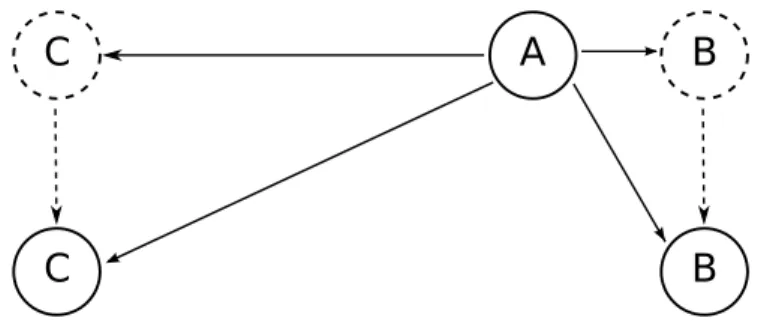
Let us consider a simple scenario: a node with only two neighbours (node B in fig.5.1) into the route of a multistep communication (A→C). It forwards
5.1 The Proposed Protocol 48
packets received from node A to node C (because communications are often bidirectional, the roles of A and C are inverted in the response phase).
A
Observed by AB
C
Observed by C
Figure 5.1: A simple model of comunication
Node A can compute B’s reputation observing the packets it receives from B. A cannot perform a direct measure of the packet it sends to B that must be forwarded to C; it can obtain an indirect response of this step observing the return traffic, which is composed by packets that B forwards to A. With this method, a unidirectional traffic in a multistep communication, involves a growth in the reputation of the j-th node known by the (j-1)-th. Clearly, a bidirectional traffic provides more information. It is obvious that a node considers its incoming traffic for reputation computation only if the origin is at least two steps far. This means that a node discards, for reputation purposes, any traffic starting from its direct neighbours because these have direct interest in those communications. So this traffic is normally forwarded, but it does not contribute to the reputation measurement.
The information acquired by direct observation are stored in a table, called Neighbour Reputation Table (NRT), which keeps track of the data amount received from closest nodes. The data that are stored in that table are separated into two different categories: forwarded and generated (fig.5.2 can help to understand better the difference).
5.1 The Proposed Protocol 49
Figure 5.2: Different packet handling
to send message to other devices. When a node i receive a message from a node j, it checks the content of the packet. If i sees that the sender of the message is j, then it stores the size of the packet as generated, otherwise as forwarded.
Due to the fact that packets in a bidirectional communication can be constituted also by a simple ack, the values stored in the NRT must consider the number of packets received and their size.
void R e p u t a t i o n T a b l e : : i n c r F o r w a r d e d ( i n t i d , long i n t B) { T c l& t c l = T c l : : i n s t a n c e ( ) ; i n t e x i s t i n g e n t r y = f i n d ( i d ) ; i f ( e x i s t i n g e n t r y >= s i z e ) e x i s t i n g e n t r y = g e t E n t r y ( i d ) ; t a b l e [ e x i s t i n g e n t r y ] . DF += B ; t a b l e [ e x i s t i n g e n t r y ] . PF++; return ; } void R e p u t a t i o n T a b l e : : i n c r G e n e r a t e d ( ID i d , long i n t B) { T c l& t c l = T c l : : i n s t a n c e ( ) ; i n t e x i s t i n g e n t r y = f i n d ( i d ) ; i f ( e x i s t i n g e n t r y >= s i z e )
5.1 The Proposed Protocol 50 e x i s t i n g e n t r y = g e t E n t r y ( i d ) ; t a b l e [ e x i s t i n g e n t r y ] . DG += B ; t a b l e [ e x i s t i n g e n t r y ] . PG++; return ; }
The two methods above implemented in C++ for NS2 allow a node to distinguish between packets generated and forwarded during a direct obser-vation. The amount of a data packet is expressed in Byte and when one of two methods is called the observer node increments the counter for that observed node, which is defined by an ID. As we are going to show later, the table of each node contains two different entries for counting the data generated or forwarded. The first one stores the packet size, instead the last one only counts each packet received by that node, e.g. a simple ack.
The following figure shows an example NRT:
Node Forwarded Generated Rloc
B 47 10 60 20 3,74
D 160 109 40 8 30,10
E 15 8 20 5 5,70
P 30 9 203 157 0,34
Table 5.1: NRT of a generic node
The C++ implementation of the previous table is the following:
s t r u c t RepTable {
ID n e t i d ; long i n t DF ;