ANTONIO COSTANZO
COMPACT AND WIDEBAND
ANTENNAS FOR RADAR
APPLICATIONS
October 2014
Developed in the framework of the project PON 01-01503, Landslides Early Warning
To my Grandfather Pietro,
who learned me to look around.
Acknowledgements
To my supervisor Prof. Sandra Costanzo. She puts a lot of effort into trying to make me a good researcher.
To Prof. Giuseppe Di Massa, Mr. Ennio Marozzo and the staff of Microwave Laboratory. I learned a lot from you-all.
To Francesco, for his everlasting friendship and to Antonio, for his irreplace-able and omnipresent support.
To all my friends. The time we spent together made me a better person. To my family...
homeland of my heart and temple of my spirit.
To all the people believing in Science. Antonio
Preface
This work provides novel antenna designs and implementation techniques, in which the main goal is the satisfaction of strict requirements necessary for their integration in modern radar systems.
Modern radars, especially the ones used in sounder applications, work in the microwave frequency range. In particular, low frequencies are suitable for early warning applications and in each system needing a long range track-ing. The most important motivation concerns the attenuation of the power associated to the signal during the path between radar and targets and vice versa; the attenuation, in general, increases with the frequency of the signal transmitted by the radar. However, the use of low frequencies, e.g. P-Band or L-Band frequency ranges, entails the employment of large antennas which dramatically waste the compactness, the practicality and the costs of the entire system, especially when the constraints require a very narrow beam, achievable only with an array composed by a large number of elements. An excessive weight of the antenna system causes a significant over-evaluating of the pointing system (engines, adapters, etc.) and protection structures for avoiding damages related to atmospheric agents, with additive costs.
In the emerging trend of software defined radar systems, most of the op-erations are delegated to software modules; this approach significantly stress classical drawbacks, as the versatility of the whole radar is mainly influenced by few hardware components, especially by the antenna device. An impor-tant aspect about the design of antennas for radar applications is related to the available bandwidth of the operations. Improving the bandwidth of the system means improving its resolution, so the use of a narrow band antenna often represents a significant bottleneck for the entire radar device. Unfor-tunately, antennas fabricated in microstrip technology, which probably are the most suitable in terms of costs and versatility, classically perform a few percent bandwidth; most of the techniques used to enlarge the bandwidth of a microstrip patch antenna deteriorate the behaviour in terms of radiation pattern, especially to the ratio of co-polar and cross-polar field components, symmetry of the field and gain.
So, the main aim of this research is to provide novel structures and tech-niques which assure a good trade-off between all these features, but maintain-ing low costs and easy designs.
The first structure proposed in this work has been designed starting by modifying the well known U-slotted Patch Antenna, one of the most-used de-sign techniques in the recent literature. The novel structure has been produced in order to easy achieve a better compromise between large bandwidth, com-pactness of the device and quality of the radiation pattern. A mathematical model has been developed in order to find the correct geometrical param-eters of the antenna and some prototypes for radar applications have been fabricated and tested in the Microwave Lab at University of Calabria, Italy.
The second structure proposed in this research is based on simplifying the geometrical features of the first one, in order to achieve almost the same behaviour but applying a simpler design. In this case two different prototype have been developed, fabricate and tested in our laboratory; the first prototype has been integrated in a radar system developed in the European Project P ON01 − 01503, whose aim is the prevention, the early warning and the analysis of landslides, while the second one, developed with a novel scheme for a dual polarized antenna, has been integrated in a mode and multi-frequency airborne radar system, developed by the research team CoRiSTA ( Consorzio di Ricerca sui TeleSensori Avanzati), under the supervision of the Italian Space Agency.
A bandwidth enlargement of the radar antenna, according to a significant size reduction, is the main goal also for the third structure here proposed, which is composed of a modified Fabry Perot Cavity Antenna fed by a rectan-gular wave-guide. In this case, a double layer structure composed of patches on a dielectric slab, acting as a meta-material, has been used to flatten the phase profile on the cavity screen, achieving a bandwidth several times larger than most of the ones already existing in literature. In particular, a novel synthesis technique mixing equivalent transmission line approach, method of moments and paraxial approximation of the wave equation in open resonators has been developed. A validation of this method, using both FEM and MoM full wave simulation analysis, has been performed and compared to the performance of similar structures.
Sommario
Il lavoro di ricerca ha inizialmente riguardato il raffinamento di una config-urazione di antenna a microstriscia da noi proposta, basata sull′utilizzo di
un doppio sistema di fenditure nell′elemento radiante. La prima fenditura, a
corona circolare, `e posta intorno al punto di alimentazione, la seconda, invece, `e assimilabile ad una U modificata. L′antenna presenta una buona banda di
funzionamento, dimensioni ridotte rispetto al patch classico ed un buon com-portamento in termini di riduzione della componente cross-polare. Partendo dai modelli matematici esistenti per la configurazione con slot ad U semplice, si `e proposto un modello empirico per questa nuova tipologia di antenna, con il quale sono stati progettati, realizzati e testati due prototipi a banda larga, uno in banda P ed uno in banda C. La fenditura a corona circolare `e stata inoltre utilizzata come base di una versione semplificata dellantenna, di-mostrando una buona estensione di questa tecnica anche per antenne a doppia polarizzazione. Un primo prototipo a polarizzazione verticale, composto da una schiera 8x4 di elementi in banda L, `e stato realizzato ed integrato in un modulo radar atto a rilevare le frane (Landslides Early Warning Radar Module). Un secondo prototipo, operante a 450MHz e sostanzialmente iden-tico al primo, `e stato utilizzato per un radar a multifrequenza sviluppato dal Consorzio di Ricerca sui Sistemi di Telesensori Avanzati (CORISTA). Per lo stesso radar, inoltre, `e stato progettato un prototipo innovativo a doppia po-larizzazione, usando come base lo stesso schema, operante in questo caso ad una frequenza di 900 MHz. Sia le misure, sia i test in volo, hanno confermato le performance di tutte le antenne progettate. L′ultima parte della ricerca ha
prodotto una tecnica di sintesi anche per le antenne per applicazioni radar basate sui risuonatori Fabry Perot. La tecnica proposta riguarda la sintesi di metasuperfici a due strati che mostrano un andamento piatto della fase del coefficiente di riflessione in una banda molto ampia. Questa struttura, di di-mensioni nettamente minori rispetto a tutte le altre presenti in letteratura, `e stata quindi utilizzata per progettare un′antenna Fabry Perot con una banda
Contents
1 Modified U-Slotted Antenna. . . 1
1.1 Introduction . . . 1
1.2 Microstrip Antennas . . . 3
1.3 U-Slotted Patch Antenna . . . 6
1.4 Modified U-Slotted Antenna . . . 10
1.4.1 Geometry . . . 10
1.4.2 Empirical model for design . . . 12
1.5 Experimental results . . . 19
1.5.1 P-Band Prototype . . . 19
1.5.2 C-Band Prototype . . . 24
2 Ring Slotted Patch Antenna for radar applications . . . 29
2.1 Ring Slotted Patch Antenna: Generalities . . . 29
2.2 Ring Loaded Patch Array for Landslides Early Warning Radar Design . . . 31
2.2.1 System Description . . . 31
2.2.2 Antenna Design and Experimental Results . . . 33
2.3 Dual Polarized Ring Loaded Patch Array for Multi-Mode and Multi-Frequency Airborne Radar Design . . . 41
2.3.1 System Description . . . 41
2.3.2 450 MHz Vertical Polarized Ring Slotted Antenna Array: Design and Experimental Results . . . 44
2.3.3 900 MHz Dual Polarized Ring Slotted Antenna Array: Design and Experimental Results . . . 50
3 Wideband Fabry Perot Cavity Antenna, Based on Metasurfaces, for Radar Applications. . . 57
3.1 Fabry Perot Cavity Antennas . . . 57
3.2 Open Resonator Theory and Wave Analysis by Parabolic Approximation . . . 59
3.3.1 Geometry . . . 62
3.3.2 A novel synthesis technique for Phase Reversing Design 65 3.3.3 Numerical results . . . 68
3.4 Compact and Wideband Fabry-Perot Cavity Antenna . . . 71
3.4.1 Geometry . . . 71
3.4.2 Results . . . 73
4 Conclusions. . . 77
References. . . 79
List of Figures
1.1 Feed techniques for microstrip patch antennas . . . 4
1.2 Feed compensation through chip resistor for microstrip patch antennas . . . 6
1.3 Basic U-slot Antenna: front view and lateral view . . . 7
1.4 Modified U-slot Antenna . . . 10
1.5 Basic U-slot Antenna: Surface currents . . . 11
1.6 Modified U-slot Antenna: Surface currents . . . 11
1.7 Simulated return loss of MUSA @ 1.8 GHz . . . 16
1.8 Simulated return loss of MUSA @ 3.5 GHz . . . 16
1.9 Simulated return loss of MUSA @ 7 GHz . . . 17
1.10 Simulated radiation pattern @ 1.8 GHz . . . 17
1.11 Simulated radiation pattern @ 3.5 GHz . . . 18
1.12 Simulated radiation pattern @ 7 GHz . . . 18
1.13 Simulated Return Loss performed by designed Classic U-Slot Antennas . . . 20
1.14 Simulated Radiation Pattern performed by designed optimized Classic U-Slot Antenna . . . 21
1.15 Photograph of P-Band Prototype during a far field measurement . . . 22
1.16 Simulated and measured return loss of P-Band Modified U-Slot Antenna Prototype . . . 22
1.17 Simulated and measured return loss of P-Band Modified U-Slot Antenna Prototype . . . 23
1.18 Measured gain vs frequency of P-Band Modified U-Slot Antenna Prototype . . . 24
1.19 C-Band prototype: comparison between simulated and measured return loss . . . 25
1.20 C-Band Prototype: far field measurements . . . 26
1.21 Measured gain vs frequency of C-Band Modified U-Slot Antenna Prototype . . . 26
2.1 Single-Polarization Ring Slotted Antenna: Top Layer Layout . . 30
2.2 Dual-Polarization Ring Slotted Antenna: Top Layer Layout . . . 31
2.3 Software Defined Radar System: block diagram . . . 32
2.4 Top layer of L-Band Ring Loaded Microstrip Patch Array . . . . 34
2.5 Simulated Return Loss for port 1 of L-Band Ring Slotted Patch Array . . . 34
2.6 Simulated S parameters from port 1 to the contiguous ports of L-Band Ring Slotted Patch Array . . . 35
2.7 Simulated Radiation Pattern @ 1.8 GHz . . . 35
2.8 Simulated Radiation Pattern @ 1.6 GHz . . . 36
2.9 Simulated Radiation Pattern @ 2.0 GHz . . . 36
2.10 Ring slotted patch array for Landslides Early Warning Application during the fabrication . . . 37
2.11 Ring slotted antenna array: fabricated modules after assembly . 38 2.12 Ring slotted antenna array: feed network . . . 39
2.13 Ring slotted antenna array: Measured Return Loss . . . 39
2.14 Ring slotted antenna array during a Far Field test @ 1.8 GHz . 40 2.15 E-Plane Far field measurements of ring slotted antenna array @ 1.8 GHz . . . 40
2.16 L-band Ring Slotted Antenna Array integrated in the Software Defined Radar for Landslides Early Warning . . . 41
2.17 Block diagram of the radar system . . . 42
2.18 General architecture of the radar system . . . 43
2.19 Four way power divider feeding the vertical polarized ring slotted array . . . 45
2.20 Polycarbonate protection of the vertical polarized ring slotted array . . . 46
2.21 Vertical polarized ring slotted array: simulated and experimental result comparison . . . 46
2.22 SAR antenna mounted into the anechoic chamber at University of Calabria . . . 47
2.23 Measured radiation pattern of SAR antenna: co-polar and cross-polar components @ 450 MHz . . . 47
2.24 Measured radiation pattern of SAR antenna: co-polar components at various frequencies, normalized respect to the one measured at 450 MHz . . . 48
2.25 Measured gain of SAR-Low antenna versus frequency at boresight . . . 49
2.26 Imager P-Band SAR antenna in flight configuration . . . 49
2.27 SAR image obtained over a coastal zone in Southern Italy (Paestum) . . . 50
2.28 UHF-High dual polarized ring slotted antenna prototype . . . 52
2.29 Single element Return Loss measurements of UHF-High dual polarized prototype . . . 52
List of Figures XVII
2.31 SAR-High antenna mounted into the anechoic chamber at
University of Calabria . . . 53
2.32 Far Field measurement at the central frequency @ 900MHz . . . . 54
2.33 Gain measurements for different frequencies: comparison between vertical and horizontal polarization . . . 54
2.34 Dual polarized SAR antenna mounted on a military helicopter for a flight campaign . . . 55
3.1 Fabry Perot Cavities . . . 57
3.2 Fabry Perot Cavity Antenna: Basic Layout . . . 58
3.3 EBG structure for antenna directivity enhancement . . . 59
3.4 AMC basic cell . . . 63
3.5 Dual layer PRS acting as a bulky metamaterial inserted as a Fabry Perot Cavity mirror . . . 64
3.6 Equivalent circuit for phase optimization . . . 66
3.7 Reflection coefficient phase in proximity of the first PRS, varying the distance between patch arrays . . . 68
3.8 Reflection coefficient phase transported near ground plane, varying the distance between patch arrays . . . 69
3.9 Reflection coefficient phase transported near ground plane, varying the varying the dimension of the patches in the first array . . . 69
3.10 Reflection coefficient phase transported near ground plane, varying the varying the dimension of the patches in the second array . . . 70
3.11 Fig. 4. Reflection coefficient phase near the ground plane after optimization . . . 71
3.12 Lateral view of the proposed Fabry-Perot Cavity antenna . . . 72
3.13 Front view, seen from the ground-plane, of the left handed Partially Reflecting Surface . . . 72
3.14 Return Loss at the beginning of the feeding waveguide varying its height . . . 73
3.15 Radiation pattern at the peak frequency @13.5GHz . . . 74
3.16 Gain at the boresight direction vs frequency . . . 75
3.17 Gain patterns on the azimuth plane at the extreme frequency values of the wideband Fabry-Perot Cavity Antenna . . . 75
3.18 Gain patterns on the elevation plane at the extreme frequency values of the wideband Fabry-Perot Cavity Antenna . . . 76
List of Tables
1.1 Common substrates for antenna design. . . 4 1.2 Modified U-Slot Antenna dimensions @ 1.8 GHz and α = 0.92 . 15 1.3 Modified U-Slot Antenna dimensions @ 3.5 GHz and α = 0.91 . 15 1.4 Modified U-Slot Antenna dimensions @ 7 GHz and α = 0.90 . . 15 1.5 Designed Classic U-Slot Antennas main dimensions . . . 19 1.6 Modified U-Slot Antenna: dimensions of P-Band Prototype . . . . 21 1.7 Modified U-Slot Antenna: dimensions of C-Band Prototype . . . . 25 2.1 Geometrical parameters of horizontal polarized ring slotted
antenna . . . 33 2.2 Geometrical parameters of horizontal polarized ring slotted
antenna array . . . 38 2.3 Geometrical parameters of P-Band vertical polarized ring
slotted antenna single element . . . 44 2.4 Geometrical parameters of horizontal polarized ring slotted
antenna array . . . 45 2.5 Geometrical parameters of dual polarized ring slotted antenna
1
Modified U-Slotted Antenna
1.1 Introduction
Microstrip antennas, shortly described in Section 1.2, are widely used in the field of radar technology since many years due to their inherent advantages in terms of low cost, small size, easy integration and low profile characteristics [1]. However, the intrinsically narrow impedance bandwidth, caused by sur-face wave losses, strongly limits their application for modern radar systems, where multiband and/or broadband operations [2, 3, 4, 5, 6] are required to guarantee high data rate, while preserving at the same time the structure compactness [7, 8]. Various approaches have been proposed in literature to improve the bandwidth of standard patch antennas, such as the adoption of thicker substrates with low permittivity, the use of multi-layer and/or copla-nar [9] configurations, based on the inclusion of parasitic elements above or around the primary radiator [10], which however causes an enlargement of the structure in the thickness or lateral direction [11]. An interesting single-layer configuration which preserves the thin profile characteristics of a standard mi-crostrip patch, while assuring wideband and/or multiband operations, is based on the use of a coaxially fed rectangular patch with a U-shaped slot. First in-troduced in [12], it has been extensively studied in literature [12, 13, 14], with claimed impedance bandwidths in excess of 30 % for air substrate thickness of about 0.08 o ad in excess of 20 % for microwave substrates of similar thickness [15]. A description of the U-Slot Antenna is given in section 1.3. The basic idea of U-slot patch antenna is to exploit the reactive cancellation between the U-slot capacitance and the feed inductance, as well as the additional U-slot resonances, to obtain a broadband frequency response. Wide impedance band-widths have been demonstrated for both linear and circular polarization [16], with a larger frequency band in the presence of an air or foam substrate, how-ever a high cross-polar radiation has been also observed due to the complex combination of U-slot and patch resonant modes [17, 18].
Approximate formulas have been introduced [18] for the ratios between the vertical and the horizontal U-slot arms, as well as between the vertical U-slot
arm and the patch width, however high cross-polar levels have been observed at the same frequencies, even if satisfying these design rules. As a matter of fact, the major drawback of U-slot patch configuration is the strong sensitiv-ity of the antenna behavior to the variation of different parameters describing the antenna geometry and the substrate. In this configuration, the currents on the patch surface cannot be separated into pure modes of either the slot or the patch, so each parameter variation causes a change in all resonant fre-quencies and could dramatically modify the antenna behavior [18]. Most of existing papers treat the design of U-slot configuration on the basis of numer-ical simulations which however precludes an easy process repeatability and a frequency scaling of the prototype. The finite-difference time domain method is adopted in [12], with the near-field to far-field transform [19, 20, 21, 22] applied to obtain the far-field radiation pattern. At the authors knowledge, the only significant attempt to establish design criteria for the U-slot patch configuration is reported in [18], where empirical formulas are presented on the basis of an accurate analysis of all structure resonances and their relations with the geometry parameters. However, design rules proposed in [18] give an approximate tool which may not work in all situations, and provide only a good starting point for successive optimization to be performed for achieving the prescribed broadband features. Starting from the insight study of the an-tenna behavior described in [18], the original U-slot geometry we propose in section 1.4 is properly modified to accomplish for a wideband response, but reducing cross-polarization effects due to the complex combination of the an-tenna and the slot modes. Cross-polarization levels represent a critical aspect for the design of broadband antennas, especially for the ones composed by single layer radiating elements, because unwanted higher-order modes excita-tion dramatically increase polarizaexcita-tion impurity. High cross polarizaexcita-tion not only leads to a distortion in the co-polarization pattern, but also reduces the gain of the antenna. A significant work was provided in [23], where a design for a dual L-strip lines exciting a triangular patch antenna, to obtain a wide operating bandwidth with cross-polarization level reduction, was presented In [24] a novel meandering probe was used to fed a wideband patch antenna on a thick substrate. Even if these technique are very effective on decreas-ing the cross-polar level on a wide band, feed designs lead to complicated structure, losing the compactness and easy feasibility that usually character-ize microstrip patch antennas. A truncated ground-plane has been employed in [25], while a novel corner-fed microstrip square patch antenna, working at millimetre frequencies, is presented in [26], where surface currents have been studied to reduce the cross polarization components without complicating the design. However, in this case, bandwidth has been prominently sacrificed to improve differences between co-polar and cross-polar levels. In our work, a sin-gle layer slotted radiating element has been employed, without complication due to particular feed design or ground-plane, in order to maintain a high level of practicality, feasibility and robustness, which represent fundamental aspects in several scenarios, like in radar applications. Maintaining the complexity of
1.2 Microstrip Antennas 3
the design only on the radiating element allowed to find simple formulas for dimensioning all the geometrical parameters, avoiding further optimizations on the structure to decrease cross-polar levels. As a matter of fact, the modi-fied U-shaped slot is introduced to properly minimize the unwanted currents giving rise to cross-polar radiation. As a further improvement with respect to the study presented in [18], the problem of thick substrates, usually required to satisfy bandwidth requirements in those applications such as P-sounding radar, is properly considered in this section.
The problem of large inductance due to the presence of a longer probe is accurately faced by adopting a proper annular gap around the coaxial feed, in order to reach a good impedance matching in the broad frequency range. Pre-liminary results have been discussed in [27, 28], an extensive theoretical dis-cussion with a detailed description of the design rules derived for the antenna synthesis is presented in Section 1.4, with numerical validations at various frequencies up to 10 GHz. Finally, experimental results on compact P-band and C-band prototypes are discussed in Section 1.5 in order to demonstrate the effectiveness of the proposed approach.
1.2 Microstrip Antennas
Microstrip antenna was first introduced in the 1950s, with the earliest studies carried out by Grieg and Englemann [29], and by Deschamp [30]. However, the first successful results started to appear only 20 years later, when By-ron described conducting strip radiators separated from a ground-plane by a dielectric substrate [31] and Munson patented the first microstrip antenna element [32]. In 80s, microstrip patch antennas were becoming much more widely known and used in a variety of communication systems. Since then, this class of antennas has been the subject of intensive research and develop-ment, so a particular attention was paid to improving mathematical models suitable for the design of the devices. Nowadays, there are several thousand papers published on the subject, as well as a number of books.
A basic microstrip antenna is composed by a metallic element supported above a large metallic ground plane by a thin dielectric substrate.The sub-strate thickness for the basic geometry is in the range of 0.01 to 0.05 free-space wavelengths. The dielectric constants of substrates are usually chosen in a range 1 to 10; for achieving low permittivity, air, polystyrene foam, or dielec-tric honeycomb are mostly employed, while ceramic or quartz based materials are usually chosen for their high values of permittivity . Common substrates used for microwave antenna design are provided in Tab. 1.1.
Dielectric constant is the ratio of the amount of electrical energy stored in an insulator, when a static electric field is imposed across it, relative to vacuum. A high dielectric constant will result in a smaller patch size which is good in most circuits though it will result in tighter fabrication tolerances. A high dielectric constant generally reduce the bandwidth. Loss tangent refers to
Table 1.1.Common substrates for antenna design. Material Permittivity Loss Tangent Arlon DiClad 870 2.33 0.0013
Arlon 25FR 3.58 0.0025
FR4 Epoxy 4.4 0.02
Teflon 5 0.03
Alumina 92 pct 9.2 0.008
the ratio of imaginary part of permittivity with real part of permittivity. A low loss tangent substrate will increase antenna efficiency and reduces microstrip losses. Thick substrate thickness will maximize bandwidth and efficiency but when it is too thick, surface-wave excitation will occur.
Several patch shapes can be considered in order to obtain a particular radiation pattern, polarization of the fields and input impedance behavior. An important aspect of the design of patch antennas is the feed technique (see Fig. 1.1) [10].
Fig. 1.1.Feed techniques for microstrip patch antennas
The simplest feeding method is represented by the use of a microstrip line, terminating with an inset in order to easily tune the value of in-put impedance.At the edge of a patch, the impedance is generally much higher than 50 ohm (e.g. 200 ohm). To avoid impedance mismatch, sections of quarter-wavelength transformers can be used to transform a large input impedance to a 50 ohm line. With the microstrip-line feed approach, an array of patch elements and their microstrip power division lines can all be designed
1.2 Microstrip Antennas 5
and chemically etched on the same substrate with relatively low fabrication cost per element. However, the leakage radiation of the transmission lines may be large enough to raise the sidelobe or cross-polarized levels of the array radi-ation. Microstrip antennas can also be fed from underneath via a probe. The outer conductor of the coaxial cable is connected to the ground plane, and the center conductor is extended up to the patch antenna. The position of the feed can be altered to control the input impedance.The coaxial probe usually has a characteristic impedance of 50 ohms. Thus the location of the probe should be at a 50 ohm point of the patch to achieve impedance matching. There are a number of terms associated with the coaxial probe. Type N, TNC, or BNC connectors are for VHF, UHF, or lower microwave frequencies. OSM or OSSM connectors can be used throughout the microwave frequencies. OSSM, OS-50 or K-connector are for millimeter-wave frequencies. The coaxial feed intro-duces an inductance into the feed that may need to be taken into account if the height h gets large, and, in addition, the probe will also radiate, leading to radiation in undesirable directions. In the case of proximity feed the line does not directly touch the antenna. For example, the open end of a 100 ohm line can be placed underneath the patch at its 100 ohm location. An open-ended microstrip line can also be placed in parallel and very close to the edge of a patch, to achieve excitation through fringe-field coupling. Another method of feeding microstrip antennas is the aperture feed. In this technique, the feed line is shielded from the antenna by a common ground plane with an aperture to transmit energy to the antenna. The upper substrate can be made with a lower permittivity to produce loosely bound fringing fields, yielding better radiation. The lower substrate can be independently made with a high value of permittivity for tightly coupled fields that don’t produce spurious radia-tions. The disadvantage of this method is increased difficulty in fabrication, but usually is the method which allows a larger bandwidth. Different defini-tions of bandwidth have to be taken into account in an antenna design. The first definition is strictly related to the reflection loss at the input terminal, in this case bandwidth is the frequency range over which the input VSWR is less than 2 (or, equivalently,over where the return loss is less than -10dB). A second definition of bandwidth is instead related to the power radiated by the antenna at different frequencies in the main direction. In this case bandwidth is the frequency range in which the radiating power, normalized respect to its maximum, is higher than -3dB. However, this two definitions are strictly related each other. Since the basic configuration allows very narrow fractional bandwidth (usually no more than 5 %) and patch dimensions near to an half wavelength, attempts to achieve compact or wideband microstrip antennas have been widely studied in recent literature for each feeding scheme. The operating bandwidth of a single linearly polarized patch antenna depends by its input reflection loss, which is inversely related to the Q-factor of the patch resonator, and by the quality of radiation. Since Q factor of a patch antenna directly depends on its volume, an effective method to enlarge the bandwidth consists into enlarge the distance between the radiating element
and the ground plane, a very practical solution involves the use of a foam substrate with low permittivity. Usually a coaxial feed is employed and some techniques in order to balance the high inductance of the probe can be con-sidered. As example, in Fig. 1.2, a coaxial fed patch with a thick substrate is shown, with a chip resistor between patch and ground-plane in order to improve input impedance [10].
Fig. 1.2.Feed compensation through chip resistor for microstrip patch antennas
In Section 1.4 and Chapter 2 of this work, in order to maintain a simple planar design, a capacitive annular slot has been cut in the patch instead of a discrete component to achieve the similar return loss features. As described in Section 1.1, a slot cut into the radiating element introduce additive resonances leading to a wideband behavior. Several slot shapes have been studied in the literature [32, 33], sometimes combined to multi-layer structures based on stacked patches[34]. However in this work a single layer approach has been proposed in order to preserve low profile, and the U-slotted configuration, described in Section 1.3, has been studied as starting point for the proposed innovative design.
1.3 U-Slotted Patch Antenna
Slotted patch antennas have been profusely studied in recent literature be-cause of their low profile preserving and easier fabrication respect to stacked configurations, modified feeding schemes, or other techniques of bandwidth enlargement. U-Slotted antennas are probably the most popular of this cate-gory, because their are symmetrical and there are few parameters to optimize in order to achieve an acceptable input impedance. The first experimental
1.3 U-Slotted Patch Antenna 7
study on this typology of antenna was published in 1995, by Huynh and Lee [11] , who developed the basic design provided in Fig. 1.3.
Fig. 1.3. Basic U-slot Antenna: front view and lateral view
The feeding point location is chosen to achieve a good input impedance without dramatically waste linear polarization and a foam substrate is inserted between patch and ground-plane in order to further enhance the bandwidth. Even if lots of articles have been written about this topic, few rigorous design procedures and theoretical analysis have been carried out. An equivalent sim-ple circuit has been provided in [35] while a deep analysis, which represent the starting point of the procedure proposed in section 1.4,has been devel-oped in [18], where a qualitative tailoring on the resonant frequencies which cause a wideband behavior are provided. In particular, a first resonant fre-quency depends on the first slot resonance in the dielectric substrate. Since the input impedance related to this resonance is very high, it does not radiate in a proper way. A second resonant frequency is related to T M01 mode of
the patch, but since the U-Slot disturbs current path, this frequency is lower than the one performed in the plain patch. A third resonance, due to both x-directed and y-directed modes and mainly related to T M20patch mode, it’s
a critical aspect of the design, because it can be associated to possible high cross polarization levels within the operative bandwidth of the antenna. The last frequency resonance is mainly the first resonant frequency of the slot in air, moderated by a x-directed resonance of the small pseudo-patch formed inside the U-slot. Approximated formulas relating geometrical parameters of the antenna and these resonant frequency are also provided in [18] and
ini-tial values for the main geometrical parameters of the antenna have been calculated modifying the classic patch antenna design based on transmission line analysis [36]. Patch length may be calculated as follows. The first step is the determination of the effective permeability of the substrate, which can be considered a constant at low frequencies and monotonically increase until its regime value. The initial value is also referred as the static value of the dielectric constant and can be calculated as:
ǫref f = ǫr+ 1 2 + ǫr+ 1 2q1 + 12h W (1.1) Once ǫref f has been defined, one can calculate the effective length
exten-sion due to the fringing effect of the fields at the border of the microstrip. ∆L= 0.412h(ǫref f+ 0.3)(
W
h + 0.264)
(ǫref f− 0.258)(Wh) + 0.8
(1.2) Since the length of the patch is effectively incremented in both sides, the effective length can be expressed as
Lef f = L + 2∆L (1.3)
So, the length of the patch can be calculated by Eq.1.1 and Eq.1.2 once the substrate height and patch width are known. In particular, patch width, for obtaining a good radiation, can be generally expressed for a microstrip patch antenna as: W = 1 2fr√µ0ǫ0 s 2 ǫref f+ 1 (1.4) being fr the frequency of resonance. In [18], eq 1.4 is considered as a starting
value, in fact a back calculation of L is necessary for the design. So:
W = 1.5(L + ∆L) (1.5) and the thickness of the substrate h is chosen as:
h= 0.06√λ0 ǫr
(1.6) Considering the geometric variables as in Fig. 1.3 and the design proposed in [18], the width of the vertical arms of the slot E,the width F and the length D of the horizontal one can be chosen as:
E= F = λres3
60 (1.7) D= √λres2
ǫref f − L + ∆L− E
1.3 U-Slotted Patch Antenna 9
being λres2and λres2referred to the second and the third resonances described
in [18]. Following this design, it is necessary to respect specific constraints for the ratio between the length C and the width D of the slot, in order to force the correct path of currents avoiding x-directed components which cause cross-polarization. In particular:
C
D ≥ 0.75 (1.9) and between the length of the slot and the width of the patch
C
W ≥ 0.3 (1.10) For obtaining the distance H between the patch and the horizontal arm of the slot, the effective permittivity and the effective length extension of a pseudo-patch with width
Wp= D − 2F (1.11)
which corresponds to a patch with the same resonance frequency of the slot. So, replacing Eq. 1.10 into Eq. 1.1 and Eq. 1.12, one obtains
ǫref f P P = ǫr+ 1 2 + ǫr+ 1 2q1 + 12 h D−2F (1.12) and ∆Lp= 0.412h (ǫref f + 0.3)(D−2Fh + 0.264) (ǫref f − 0.258)(D−2Fh ) + 0.8 (1.13) So, H can be calculated as:
H = L − E + 2∆Lp+ 1 √ǫ ref f P P (λres4 4 − 2C − D) (1.14) The value C must be chosen in order to respect the condition
L ≥ H + E + D (1.15) for achieving a consistent geometry. Even if this study represents an excellent starting point for design, it does not take into account the influence of position of the feed point in both return loss and polarization behavior, and do not solve some drawbacks due to high cross-polar levels caused by horizontal current path if geometry does not respect very strict constraints.
Following the design in [18] is precluded the possibility to design an an-tenna with reduced size respect to the classic patch.
In order to solve these problems, a new typology of slot is presented in our work, in this case current paths are balanced in order to avoid cross-polarization without complicating the design and in order to achieve a signif-icant compactness respect to both classic patch and U-Slotted patch. In this particular configuration the optimal feeding point is always in the center of the patch and a simple design procedure is proposed in Section 1.4.
1.4 Modified U-Slotted Antenna
1.4.1 Geometry
As discussed in [18], the combination of antenna and slot modes gives rise to undesired x-directed currents, which produce a high cross-polar field compo-nent unless the ratio between the vertical arm C and the horizontal arm D does not satisfy a specific criterion. This means that bandwidth requirements cannot always be satisfied while guaranteeing, at the same time, a low cross-polar effect.The antenna configuration proposed in this work is illustrated in Fig. 1.4. The basic U-slot geometry is properly modified to maintain its band-width features, but reducing at the same time the high cross-polar radiation often present at some frequencies within the operating range.
Fig. 1.4.Modified U-slot Antenna
As illustrated in Fig.1.4, the U-slot arms are properly shaped to minimize the paths of unwanted x-directed modes. In particular, a cut is realized along the horizontal U-slot direction, thus reducing the extent Ht of the new hor-izontal arm. To have a better tuning of the operating bandwidth, unequal lengths are chosen for the two U-slot vertical arms, and in order to achieve compactness, current path length has been increased enfolding the vertical arms on themselves. Geometry has been chosen also in order to be suitable for a central feeding point, avoiding the complexity of the effects due to different paths of the current on the slot which cause mismatch and cross-polarization. As a further variation with respect to the existing U-slot design [18], a proper capacitive anular ring is introduced around the feed [36] to compensate for the large probe inductance due to the presence of thick substrates, which could prevent the impedance matching. This problem is particularly evident
1.4 Modified U-Slotted Antenna 11
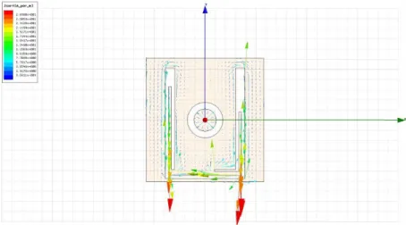
at low frequencies, for applications such as P-band radar, where broadband operations impose the use of a large dielectric thickness, with a consequently increased feed inductance strongly limiting the achievable bandwidth to less than 10 %. For comparison purpose, a plot of surface currents distribution of both classic U-Slot Antenna and Modified U-Slot Antenna working at the same central frequency are provided in Fig. 1.5 and 1.6. The simulations have been carried out by Finite Element Method trough the commercial software HFSS 12.
Fig. 1.5.Basic U-slot Antenna: Surface currents
In the case of Classic U-Slotted Antenna, a relevant x-directed current circulation can be observed, due to the transition of the current flow around the slot thus causing a more relevant cross-polar level with respect to the con-figuration proposed in this work where a strong y-directed current component is enforced into the metal stripes inside the vertical arms of the slot. The asymmetrical configuration of the cut permit to balance the flows in order to dramatically decrease the average x-directed current component which causes cross-polarization.
Since the position of resonances is similar in both antennas, simulations in the entire working bandwidth have been performed, achieving the same behavior shown in Fig. 1.5 and Fig. 1.6. Since the scope of the two simulated structure is identical, so one can qualitative note how, achieving the same working frequency range, a dramatic decreasing of patch surface size (about 50 %) is obtained. Once validate the effectiveness of the design, a campaign of extensive simulations have been carried out through Method of Moments analysis in order to find a model, similar to the one proposed in [18] , which quantitative describes an effective design technique for the Modified U-Slot Antenna.
1.4.2 Empirical model for design
While the behavior of the resonant frequency is similar in both classical and modified U-Slot Antennas, an improved design strategy has been developed in this work to face the problems due to the frequency shift and high cross-polar radiation, both caused by the hybrid combination of the patch and the slot modes, without introducing particular constraints in the design once calcu-lating the geometrical parameters. Starting from the studies in [18] , cited in Section 1.3, a simple empirical method, based on the adaptation of the ex-isting formulas for microstrip patch antenna and microstrip U-Slotted patch antenna to the proposed design, has been proposed. At this purpose, the an-tenna layout is properly modified as described in Subsection 1.4.1, with the further inclusion of a proper anular ring to guarantee the prescribed wide-band features even in the presence of thick substrates, usually required at low frequencies for an effective Q factor lowering and a significant bandwidth improvement. The details of the proposed design procedure are described by the following steps:
❼ Fixed the design central frequency f, compute the shifted frequency f0to
be adopted in the successive parameters evaluation, by the expressions: f0= 1.101f − 0.043[GHz], f ≤ 2.75GHz (1.16)
f0= 1.214f − 0.3539[GHz], 2.75GHz ≤ f ≥ 4.975GHz (1.17)
1.4 Modified U-Slotted Antenna 13
❼ From the knowledge of the shifted frequency, compute the value of the patch width W by the expression:
W = c 3.55f0
√ǫ
ref f (1.19)
and the value of the patch length L solving equation 1.3 , but using, for substrate thickness, the equation:
h= c 11f0
(1.20) From the equations reported above, a significant reduction of the overall antenna dimension (up to 40 %) is obtained with respect to the designs existing in literature [18]. Furthermore, the new expression provided for the substrate thickness automatically satisfies the rule imposed in [18], fixing a lower limit below which a broadband operation is not obtainable. On the basis of the proposed empirical formulas, it is straightforward to derive that, in the presence of low permittivity substrates, the values of patch dimensions W and L are quite similar and the patch is almost square. ❼ Compute the geometrical parameters E , F , HT , G , WT , WT1, G1and
H by the following expressions:
E= F = c 35f0 (1.21) Gǫ= G + Gδ (1.22) G=0.0888c f0 (1.23) Gδ = 0.0157 c f0 (√ǫr− 1) (1.24) W t=E 3 (1.25) Wt1= H = G1= Ht (1.26)
Compute the U-slot width D according to the existing model [18], but adopting the new geometrical parameters as:
D= c
αf0√ǫr − 2(L + 2∆L− E)
(1.27) where the term α is the only tuning parameter adopted in the synthesis procedure, whose values can be chosen in the range between 0.8 and 0.92 to guarantee an adequate matching in the operating frequency range.
❼ Compute the total U-slot vertical length C by the new expression: C= L − ∆L (1.28)
and the parameters C1 and C2 of the Modified U-Slot by the following expressions: C1= ( c 4f0√ǫr − E 2)(1 + Dαf0 c ) (1.29) C2= ( c 4f0√ǫr − E 2)(1 − Df0 αc ) (1.30) ❼ Compute the values of the inner and outer radii R1 and R2 as follows:
R1= 6.189 ∗ 106f0−0.9535[m] (1.31)
R2= 2.577 ∗ 105f0−0.8166[m] (1.32)
with f0 in Hz.
The outlined method for the synthesis of Modified U-Slotted Antenna highlights a significant difference with respect to the design procedure pro-posed in [18]. As a matter of fact, in the original approach, the operating bandwidth is always fixed equal to the difference between the fourth and the second resonant frequencies of the structure. This criterion does not always guarantee to achieve the desired frequency band operation, and the useful antenna bandwidth could be less than the fixed one, as declared by the same authors in [18]. In our approach, the modified U-slot configuration, together with the adopted circular ring, leads to have a minimum useful bandwidth of 15 %, which can be simply obtained by applying the synthesis procedure outlined into this section. A few iterations with respect to the parameter α are required to optimize the matching in the operating frequency range and the overall design procedure is able to guarantee a frequency band between 15 % and 20 %. The empirical formulas presented in the previous section are numerically validated at different operating frequencies between 1 GHz and 10 GHz. Firstly, three prototypes are designed, respectively working at 1.8 GHz, 3.5 GHz and 7 GHz, by assuming a foam substrate ( ǫr = 1.07). The
synthesis procedure is applied for all assumed designs, starting from a value of α = 0.88 and using a step ∆α = 0.01 . The process is stopped after a few iterations (typically between 2 and 4), when reaching a bandwidth of about 15 %. All designed antennas have a thickness h as given by 1.20. In 1.2, 1.3 and 1.4 the value of all geometrical parameters , according to the proposed model, are presented for each frequency.
The return loss curves for the three prototypes, reported in Fig. 1.7, Fig. 1.8, and Fig. 1.9, properly show a bandwidth of about 15 %, as imposed in the synthesis procedure.
1.4 Modified U-Slotted Antenna 15 Table 1.2. Modified U-Slot Antenna dimensions @ 1.8 GHz and α = 0.92
Parameter Dimension [mm] Parameter Dimension [mm]
L 58.1 D 21.9 W 53.3 E 4.4 C 49.4 F 4.4 C1 39.8 Wt 1.5 C2 29.8 G 11.9 Ht 1.5 R2 8.6 H 1.4 R1 6.7 G1 1.5 Wt1 1.5
Table 1.3. Modified U-Slot Antenna dimensions @ 3.5 GHz and α = 0.91 Parameter Dimension [mm] Parameter Dimension [mm]
L 28.9 D 11.8 W 26.5 E 11.2 C 24.5 F 2.2 C1 20.0 Wt 0.7 C2 14.6 G 6.3 Ht 0.7 R2 4.1 H 0.7 R1 3.6 G1 0.7 Wt1 0.7
Table 1.4. Modified U-Slot Antenna dimensions @ 7 GHz and α = 0.90 Parameter Dimension [mm] Parameter Dimension [mm]
L 13.76 D 6.07 W 12.65 E 1.05 C 11.7 F 1.05 C1 9.58 Wt 0.35 C2 6.81 G 3.05 Ht 0.35 R2 2.18 H 0.34 R1 2.07 G1 0.34 Wt1 0.34
Fig. 1.7.Simulated return loss of MUSA @ 1.8 GHz
1.4 Modified U-Slotted Antenna 17
Fig. 1.9.Simulated return loss of MUSA @ 7 GHz
A plot of far fields, for each frequency range design, is provided in Fig. 1.10, Fig. 1.11, and Fig. 1.12
Fig. 1.11.Simulated radiation pattern @ 3.5 GHz
Fig. 1.12.Simulated radiation pattern @ 7 GHz
Far-field patterns (H-plane), indicate a cross-polar level, at the central op-erating frequency, properly below the co-polar one, with a difference of about 33 dB between them along the main beam direction. This good cross-polar behavior is maintained within the full frequency range, as it can be observed in the same figures at different operating frequencies. Similar behavior have been obtained in the E-Plane.
1.5 Experimental results 19
1.5 Experimental results
1.5.1 P-Band Prototype
In order to assess by experimental results the validity of the proposed synthesis procedure on Modified U-Slot Antenna, two different prototypes suitable for P-band and C band radar applications have been realized and successfully tested in the Microwave Lab at University of Calabria. A first prototype is assumed to work at a central frequency f0 = 450M Hz, with an operating
bandwidth of about 15 %, useful for P-sounding radar. A foam substrate (ǫr=
1.07) is assumed, with an upper thin layer (0.762 mm) of dielectric Diclad870 (ǫr = 2.33), uniquely adopted for robustness reason, to better support the
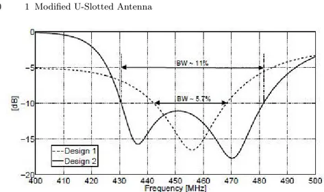
U-shaped slot. Design rules presented in [18] are considered to have a starting (and reference) point for developing two different classic U-slot antennas, the first one without optimization respect to the model proposed in [18] (Design 1) and the second one after an optimization of both bandwidth and dimensions (Design 2), as reported in Tab. 1.5; these designs are produced in order to directly compare the performance of the existing U-Slot Antenna with the prototype proposed in this study.
Table 1.5.Designed Classic U-Slot Antennas main dimensions Configuration name Patch Width [W] Patch Length [mm]
Design 1 49.26 27.50
Design 2 36.10 26.12
Fig. 1.13.Simulated Return Loss performed by designed Classic U-Slot Antennas
Simulated return loss (Fig.8) shows a reduced bandwidth of about 5.7 % with respect to the imposed constraint, thus requiring an optimization refinement to obtain Design 2 configuration also reported in 1.5. A larger bandwdith of about 11% is obtained in this case, but lower again with respect to the prescribed goal of 15 %. Furthermore, when approaching the frequency band extremes, a cross-polar field level in the H-plane comparable to the co-polar component is produced, as yet observed in [18], thus indicating a reduction of the effective useful bandwidth, as shown in Fig. 1.14, where both co-polar and cross-polar field components of Design 2 configuration, are shown at different frequencies belonging to the operative Return Loss bandwidth of the antenna.
1.5 Experimental results 21
Fig. 1.14. Simulated Radiation Pattern performed by designed optimized Classic U-Slot Antenna
To overcome cross-polar limitations of Standard U-Slot Antenna design, the modified structure presented in 1.4.1 has been developed using the pro-cedure described in 1.4.2, without further optimization steps. The values as-sumed by the geometrical parameters, obtained through the empirical model proposed, are indicated in 1.6, while a photograph of the fabricated proto-type, during a far field measurement in the anechoic chamber at University of Calabria, is shown in Fig. 1.15.
Table 1.6. Modified U-Slot Antenna: dimensions of P-Band Prototype Parameter Dimension [cm] Parameter Dimension [cm]
L 24.3 D 15.6 W 23.1 E 1.8 C 21.8 F 1.8 C1 18.1 Wt 0.5 C2 23.1 G 5.9 Ht 0.5 R2 3.5 H 0.6 R1 2.2 G1 0.5 Wt1 0.5
Fig. 1.15.Photograph of P-Band Prototype during a far field measurement
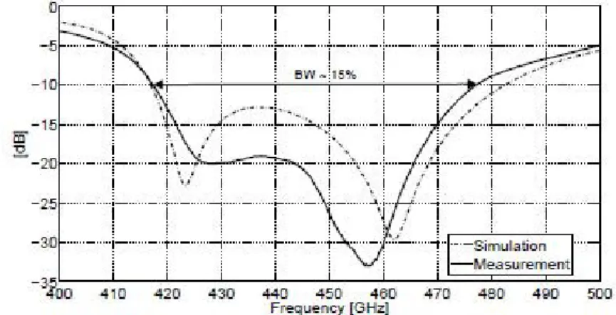
The P-band antenna is tested into the Microwave Laboratory at University of Calabria, in terms of return loss response as well as radiation pattern be-havior. A bandwidth of about 15 % is successfully obtained, with a very good agreement between simulated (Ansoft Designer Version 3.5) and measured data, as reported in 1.16.
Fig. 1.16.Simulated and measured return loss of P-Band Modified U-Slot Antenna Prototype
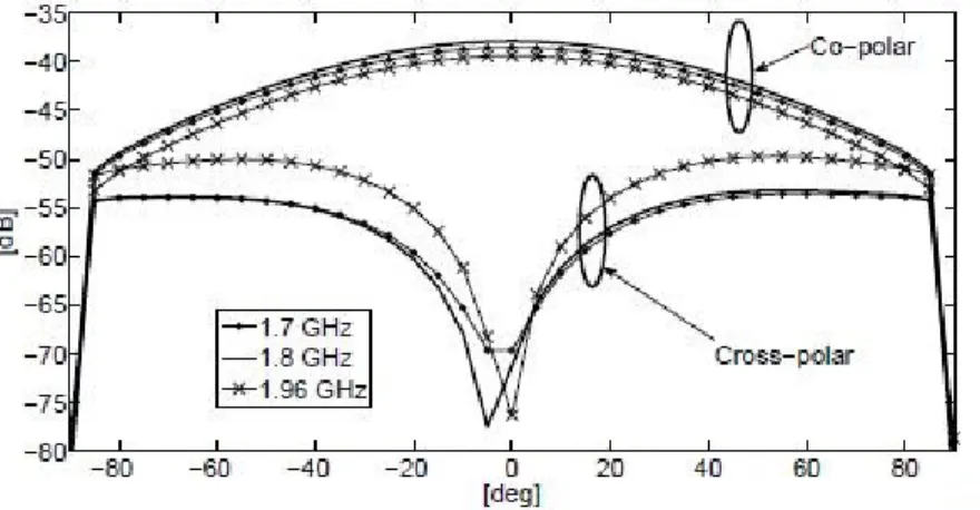
Furthermore, the wideband response is confirmed by the radiation features, illustrated in 1.17, for both H-Plane and E-Plane.
1.5 Experimental results 23
Fig. 1.17.Simulated and measured return loss of P-Band Modified U-Slot Antenna Prototype
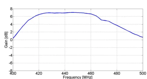
The cross-polar component remains properly below the co-polar field at the frequency band extremes, while in the original reference design [65] a poor difference of about 6dB between the co-polar and cross-polar ones is performed in the upper bound frequency limit. As a further improved feature with respect to Standard U-Slot Antenna, is the strong size reduction of the prototype, equal to 50 % of the total area surface. In order to provide a final verification of the wideband behavior of the fabricated prototype, a multi-frequency radiation pattern measurement has been performed in the anechoic chamber, the measured gain in the azimuth plane vs frequency is shown in Fig. 1.18
Fig. 1.18.Measured gain vs frequency of P-Band Modified U-Slot Antenna Proto-type
A wideband -3dB frequency range has been performed, thus confirming the wideband feature of the measured return loss.
1.5.2 C-Band Prototype
In order to further experimentally validate the empirical model, the same de-sign process to that adopted for the P-band prototype is applied to synthesize a C-band antenna, working at a central operating frequency fo = 4.3 GHz.
A foam substrate ( ǫr = 1.07) is again assumed, with an upper thin (0.762
mm) layer of standard dielectric Di-Clad 870 ( ǫr = 2.33) to mechanically
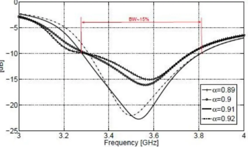
enforce the radiating structure, as in the previous case. The synthesis proce-dure outlined in Section 3 is applied by initially assuming a value α = 0.89 , and obtaining, after a few iteration steps ( α = 0.91), the final configuration whose dimensions are reported in 1.7.
The correct behavior of C-Band prototype (Fig. 1.19 ) is firstly tested by measuring the return loss, which is successfully compared in Fig. 1.14 with the simulation results (performed with Ansoft Designer v 3.5).
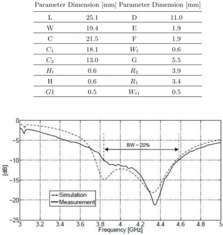
1.5 Experimental results 25 Table 1.7.Modified U-Slot Antenna: dimensions of C-Band Prototype
Parameter Dimension [mm] Parameter Dimension [mm]
L 25.1 D 11.0 W 19.4 E 1.9 C 21.5 F 1.9 C1 18.1 Wt 0.6 C2 13.0 G 5.5 Ht 0.6 R2 3.9 H 0.6 R1 3.4 G1 0.5 Wt1 0.5
Fig. 1.19.C-Band prototype: comparison between simulated and measured return loss
In this case the fabricated antenna shows a large measured bandwidth approximately equal to 20 %. The wideband feature is further confirmed by the measured radiation patterns in Fig. 1.20 .
Fig. 1.20.C-Band Prototype: far field measurements
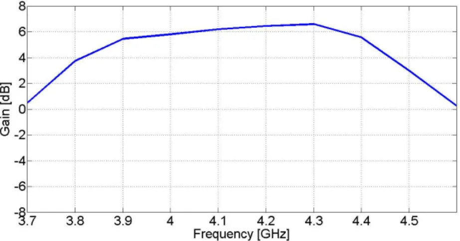
Cross-polar components properly remain at an acceptable level below the co-polar field within the operating frequency range, like with P-Band Pro-totype. Also in this case, a compact antenna (about half-size in respect to the standard configuration) with broadband features and reduced cross-polar effects is obtained. In order to further validate the wideband behavior of the proposed antenna, radiation patterns have been tested at different frequencies in -10dB frequency range. A plot of measured gain vs frequency in H-Plane is shown in 1.21, while identical results have been performed in E-Plane mea-surements.
Fig. 1.21. Measured gain vs frequency of C-Band Modified U-Slot Antenna Proto-type
Wideband behavior is confirmed by gain measurement, with a peak value around 7dB, similar to classic microstrip antenna configurations, according to a -3dB gain bandwidth even larger than the -10dB return loss one. So, the
1.5 Experimental results 27
new geometry layout for compact U-slotted patch proposed in this chapter, with improved features in terms of cross-polarization effects, may represent a valid antenna design in those radar applications which require a broadband behavior without wasting its performance in terms of quality of the radiation pattern but maintaining reduced surface area and an easy fabrication process. Arrays made up by a simplified version of the proposed antenna have been integrated in two different innovative radar system. The design of the antenna, the experimental validation of the simplified design and a brief discussion on the feature of the whole radar systems, are provided in Chapter 2 of this work.
2
Ring Slotted Patch Antenna for radar
applications
2.1 Ring Slotted Patch Antenna: Generalities
A correct design of antennas is a critical aspect for a generic radar system, especially for modern devices which allow the possibility to switch different operative modes. Software Defined Radar Systems and Mode Multi-Frequency Radars (briefly described in this chapter) allow a huge flexibility in respect to the previous devices, permitting to change some operative pa-rameters on fly in order to practically modify their functions in the strength of the scenario their are operating. Clearly, a reuse of hardware components for different purposes (Multi-Mode Radar) or the substitution of hardware com-ponents with software modules which perform the same function also permit a consistent advantage in terms of costs. As described in Subsection 2.2 and Subsection 2.3 , in order to maintain these features, avoiding performance bot-tlenecks and cost increasing, the radar antenna have to be designed respecting several constraints, usually stronger than the one for other applications.
Since different polarization of the scattered waves give different informa-tion in the scenario under analysis, a particular atteninforma-tion have to be paid to the cross-polar level, especially if the radar is designed to operate with a linear polarization and the signal process modules need a very clean received signal to obtain significant results . Bandwidth is another critical aspect, es-pecially for Software Defined Systems, in fact a broadband antenna does not reduce the flexibility of the radar system if new signal processing algorithms are gradually added after final hardware design. A large bandwidth is also nec-essary to achieve the high resolution required by most of modern applications. Compactness and low profile are also required if the operating frequency is rel-atively low (as P-Band applications) or an array of lots of elements is needed in order to have a sufficient narrow beam width. Small differences in weight and size of antennas, for some specific scenarios (like aerospace applications), may lead to a huge increment of implementation and management costs, so a good trade-off between electromagnetic properties and geometric properties of transmitting and receiving antennas, are necessary for their suitability in
the radar field. In this section, a simplified version of the Modified U-Slotted Antenna proposed in Chapter 1, has been integrated in two different radar systems. The basic layout is shown in Fig. 2.1
Fig. 2.1.Single-Polarization Ring Slotted Antenna: Top Layer Layout
Basic equation for Microstrip Rectangular Patch length (Eq. 1.3) and the proposed one for Modified U-Slot Antenna patch width (Eq. 1.19) have been used as a starting point for the design. A starting point for finding the geo-metrical parameters of the ring are provided, like proposed in Chapter 1 for the complete configuration, in Eq. 1.31 for the outer radius and Eq. 1.32 for the inner one. Even if in this case an optimization of the geometric parame-ter is required, achieving a good trade-off between large bandwidth behavior and compactness of the surface area is possible after few tuning of the main geometrical variables.
Even if the first theoretical analysis of the ring shaped slot around the feeding point has been developed in [37], the structure proposed in this chap-ter is, by our knowledge, the first one allowing a dual-polarization design. In particular, the layout outlined in Fig. 2.1 has been properly modified to simultaneously allow both vertical and horizontal polarization, as shown in Fig. 2.2.
2.2 Ring Loaded Patch Array for Landslides Early Warning Radar Design 31
Fig. 2.2.Dual-Polarization Ring Slotted Antenna: Top Layer Layout
Starting from the design of a single polarized antenna, with the duplication of the feeding and the annular slot, after few variations of the geometrical parameters a large bandwidth can be obtained, according to a significant size reduction and an acceptable isolation between the two polarization, quite improved by the circular ring. This simple design represent the basic element for design of the antenna arrays integrated into the two radar system described in Section 2.2 and Section 2.3.
2.2 Ring Loaded Patch Array for Landslides Early
Warning Radar Design
2.2.1 System Description
Military operation, like target detection, target recognition, surveillance, and other specific applications, like meteorology and air-traffic control, had rep-resented, in the early development of radar technology, the main field of ap-plication. However, in the same way as other electronic devices, in the recent years a large amount of new possible applications, in different disciplines (au-tomotive, medical science, biology), have been outlined. In order to satisfy requirements due to large-scale commercial applications, modern radar sys-tems have to perform the same operations typical of a classical radar, but according to significant cost reduction and a strong adaptability. A new con-cept of design, called Software Defined Radar (SDRadar), may lead to new interesting developments in radar technology because of the possibility of per-forming most of the basic operations (i.e., mixing, filtering, modulation and demodulation) employing software modules in order to eliminate most of the specific hardware and their costs [38].
Since signal generation and signal processing parameters may be easily adapted on the fly to the task under consideration, another important advan-tage due to the Software Defined approach is related to a significant improve-ment in the versatility of the system. The solution proposed by the team of Microwave Lab at University of Calabria, for a low cost SDRadar system de-velopment, has been obtained by the adoption of the Universal Software Radio Peripheral (USRP) transceiver. A first attempt to apply USRP for target de-tection was performed in [39], in which a SDRadar system was implemented through the use of first generation USRP, but the narrow bandwidth imposed by the available USB connection limited the resolution. So, USRP NI2920, which allows a larger bandwidth respect to the USRP of first generation, has been considered for developing a Software Defined Radar [40]. The design proposed in [39] has been developed to create a low cost, compact and flex-ible solution; potentially this scheme can be easily employed in different use cases without significant hardware modification, with the possibility to create a multi-purpose radar system. A simplified block diagram of the SDRadar system is reported in Fig. 2.3.
Fig. 2.3.Software Defined Radar System: block diagram
The USRP 2920 platform is used to transmit and receive data by a lin-ear array antenna composed by the element proposed in this chapter. The whole system is controlled by a LabVIEW application running on a compact Single Board Computer (SBC). It is able to perform the signal processing useful for the characterization of the area under analysis, but it is designed also to control a motor system permitting to rotate the antenna, thus giving a scanning feature useful for an accurate surface monitoring in different di-rections. A Power Amplifier (PA) and a Low Noise Amplifier (LNA) increase the signal power along both the transmission and the receiving paths and a
2.2 Ring Loaded Patch Array for Landslides Early Warning Radar Design 33
circulator has been used in the indoor test to employ a unique antenna both in transmission and in receiving path, further reducing the total hardware costs and the size of the entire device. In particular, by signal processing point of view, a Stretch Processing approach has been implemented in the system to fully take advantage of the benefit of NI2920 enhanced bandwidth. In order to penetrate vegetation, L-Band frequency range as been chosen, according to an horizontal polarization of antennas.
In outdoor tests, however, two distinct antennas have been adopted in transmission and receiving path in order to improve Signal to Noise Ratio. The final prototype has been successfully integrated in the project P ON 01 − 01503, financed by European Community , in which several Italian teams have collaborated, most of them belonging to University of Calabria. The main aim of the project is related to the landslide Early warning on Italian highways. 2.2.2 Antenna Design and Experimental Results
Starting by the design method developed in Chapter 1 of this work, but ap-plied to the simplified version proposed in 2.1, an array of antennas has been synthesized, fabricated and tested in order to be easily integrated in the soft-ware defined radar for landslides early warning application briefly described in the first part of this section. So, according to layout in Fig. 2.1, a large band ring slotted patch antenna, with horizontal polarization has been developed, and the dimensions of main geometrical parameters on the basic cell are pro-vided in Tab. 2.1. Dimensions are related to a L-Band prototype, working at the central frequency of 1.8 GHz, according to the radar operative frequency. Starting by dimensions outlined in Tab. 2.1, an array composed by 8x4
ele-Table 2.1.Geometrical parameters of horizontal polarized ring slotted antenna Parameter Value [mm]
Ground Plane Length 100 Ground Plane Width 100
Patch Length 72
Patch Width 55
External Ring Radius 7 External Ring Radius 4.55 Feed Point Coordinates ( -17, 0)
Foam Height 20
Support Substrate Height 0.762
the integration with the rest of the radar system. In particular, the top layer of the entire array is provided in Fig. 2.4 .
Fig. 2.4.Top layer of L-Band Ring Loaded Microstrip Patch Array
Total dimensions of the array are 80x40 cm, while the distance between contiguous elements is 10cm, equal to 0.6 wavelengths at the central frequency 1.8GHz. Simulations were carried out with both Method of Moments (using the commercial software Ansoft Designer V. 3.5) and Finite Element Method (using Ansoft Hfss V. 12), but results were substantially the same. A plot of the return loss at port 1 (referred to the design in Fig. 2.4 ), produced by using MoM, is provided in Fig. 2.5.
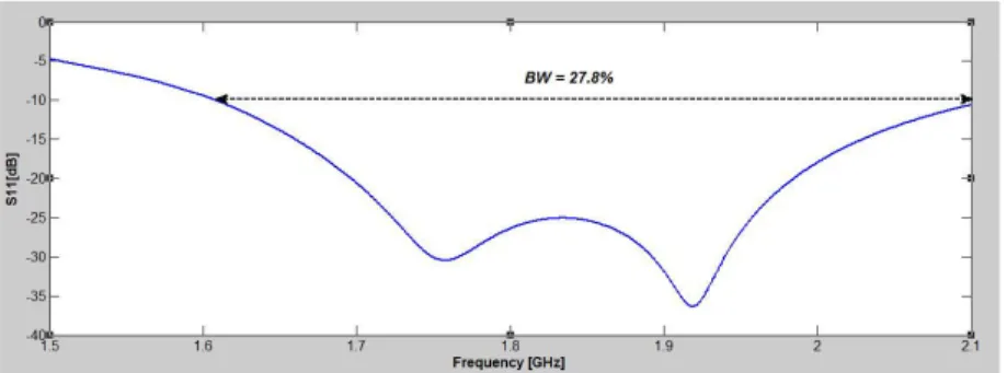
Fig. 2.5. Simulated Return Loss for port 1 of L-Band Ring Slotted Patch Array
As in the case of Modified U-Slotted Antenna outlined in Chapter 1 of this work, wideband operations are achieved (27.8 % respect to the central
2.2 Ring Loaded Patch Array for Landslides Early Warning Radar Design 35
frequency), according to a significant size reduction of the radiating element. Clearly, dimensions of the single radiating elements does not affect signifi-cantly total dimensions of the array (since the total number of elements in a column or in a row is established in order to obtain a certain beam width in the elevation plane or in azimuth plane), however, a small size element dramatically reduce coupling between contiguous elements when the distance between them is fixed a priori. So, in Fig. 2.6 is shown the transmission coef-ficient between Port 1 and the contiguous ports.
Fig. 2.6. Simulated S parameters from port 1 to the contiguous ports of L-Band Ring Slotted Patch Array
One can notice how the simulated transmission coefficients between con-tiguous port remain under the threshold of -15dB, maintaining a flat behavior, in the entire operation bandwidth. How explained in Chapter 1, a fundamen-tal aspect of a radar antenna design deals with the maintaining of a low cross-polar level in both E-Plane and H-Plane, especially in the angle range effectively scanned by the radar system, in the entire frequency range. In Fig. 2.7 is shown the simulated radiation pattern, in both E-Plane and H-Plane, at the central operating frequency of 1.8GHz.
How shown in 2.7, proposed array achieves a beam width of 10 degrees in the azimuth plane and 21 degrees in the elevation plane, how required by the application. Cross-polar electric field components are properly below the co-polar one for both E-Plane and H-Plane in the whole useful scanning angle range, especially in broadside direction, radiation pattern maintains its symmetry neitherless the presence of the annular slot with contributes to radiation. Peak gain is about 21 dBi. In order to further validate results obtained by this design, radiation pattern has been simulated in the lower extreme of -10dB Return Loss bandwidth (Fig. 2.8) and in the upper one (Fig. 2.9).
Fig. 2.8.Simulated Radiation Pattern @ 1.6 GHz
Fig. 2.9.Simulated Radiation Pattern @ 2.0 GHz
Cross-polar level of field components is properly maintained below the co-polar level, no significant variations between radiation patterns at the different frequencies in the operative bandwidth can be appreciate neither in the radia-tion shape nor in the peak value, so a -3dB radiaradia-tion pattern bandwidth larger than the return loss bandwidth has been achieved. The designed prototype has been fabricated in the Microwave Lab of University of Calabria.
2.2 Ring Loaded Patch Array for Landslides Early Warning Radar Design 37
For practicability, two identical square modules of 4x4 elements have been realized and placed side by side. The two realized modules have been real-ized through an LPKF numerical control machine while coaxial feed have been manually soldered to the ground-plane and further connected to the plane containing the radiating elements, by piercing the foam block. Different blocks have been assembled using a thin adhesive substrate of Arlon CuClad 870, with the same permittivity of the support substrate (Arlon DiClad 870) in order to avoid to introduce useless discontinuity in the structure. An ad-ditive substrate composed by fiberglass has been inserted under the ground-plane for increasing the robustness of the structure. In Fig. 2.10 is provided a photograph of a module, before assembly.
Fig. 2.10. Ring slotted patch array for Landslides Early Warning Application dur-ing the fabrication
In Tab. 2.2 are outlined the main geometrical parameters of each fabricated module. Since radar antenna has been designed for an outdoor application, copper radiating elements have been covered by a thin silver film in order to preserve them from oxidation processes. A photograph, showing the two modules, once assembly was completed, is provided in Fig. 2.11.
Table 2.2. Geometrical parameters of horizontal polarized ring slotted antenna array
Parameter Value [mm]
Module Length 400
Module Width 400
Vertical distance between edges 28 Horizontal distance between edges 45 Number of radiating elements 16 Adhesive thickness 0.038 Support substrate thickness 0.762 Fiberglass Thickness 1.6
Foam Thickness 20
Copper thickness 0.036
Fig. 2.11.Ring slotted antenna array: fabricated modules after assembly
Another important aspect involving the design of the final array concerns feed network. In particular, the feed network has been provided by two com-mercial power dividers with 16 output ports and input connected trough coax-ial cables to a smaller power divided where input is in turn connected or to the circulator (in the configuration using only one antenna in both transmis-sion and receiving path, see 2.3) or directly to the receiving path (in this case a standard 20dB gain Horn was used for transmission). The realized feeding network is shown in Fig. 2.12.
2.2 Ring Loaded Patch Array for Landslides Early Warning Radar Design 39
Fig. 2.12.Ring slotted antenna array: feed network
As shown in Fig. 2.12, an iron shell (painted in white) has been realized in order to fasten the three power dividers and the array to the engine used for angle scanning (which is directly controlled by the Software Defined Radar). A plexiglass cornice has been used to secure the two modules to the shell. For preserving connections and feed network from atmospheric agents, all the edges of the iron shell are in turn covered by thin plexiglass sheets. Before being integrate in the complete radar system, the ring loaded patch array has been tested in the anechoic chamber of Microwave Lab at University of Calabria. Return Loss measurements have been carried out on the prototype, and results have been provided in Fig. 2.13.
![Table 1.6. Modified U-Slot Antenna: dimensions of P-Band Prototype Parameter Dimension [cm] Parameter Dimension [cm]](https://thumb-eu.123doks.com/thumbv2/123dokorg/2878732.10151/40.918.288.619.671.853/modified-antenna-dimensions-prototype-parameter-dimension-parameter-dimension.webp)