Scuola Dottorale di Ingegneria
Sezione di Ingegneria dell’Elettronica Biomedica, dell’Elettromagnetismo e delle Telecomunicazioni
XXIII Ciclo
Codifica Distribuita di Sorgenti Video 3D
Veronica Palma
Docente-guida:
Prof. Alessandro Neri
Coordinatore: Prof. Lucio Vegni
Scuola Dottorale di Ingegneria
Sezione di Ingegneria dell’Elettronica Biomedica, dell’Elettromagnetismo e delle Telecomunicazioni
XXIII Ciclo
Distributed Coding of 3D Video Sources
Veronica Palma
Advisor:
Prof. Alessandro Neri
Coordinator: Prof. Lucio Vegni
be reproduced or transmitted in any form or by any means, electronic or mechanical, including photocopy, recording, or any information storage and retrieval system, without permission in writing of the author. The University “Roma Tre” of Rome, Italy, has several rights in order to reproduce and distribute electronically this document.
Department of Applied Electronics
Laboratory of Telecommunications (COMLAB) PhD Thesis: Distributed Coding of 3D Video Sources
Author: Veronica Palma
Advisor: Prof. Alessandro Neri (University “Roma Tre” of Rome, Italy) Year: 2011
This thesis describes the research carried out within the COMLAB Laboratory of the University “Roma Tre” of Rome, Italy, from 2008 to 2010.
Codifica distribuita di sorgenti video 3D
Negli ultimi anni, diverse tecniche di codifica video hanno raggiunto una grosso successo a livello commerciale ed ´e oramai chiaro che i sistemi video digitali sostituiranno com-pletamente tutti i sistemi video analogici. Le strategie di codifica video convenzionali sono basate sull’ idea che ´e compito del codificatore calcolare le statistiche della sorgente, creando cos´ı un codificatore complesso che interagisce con un semplice decodificatore. Broadcasting, video on demand e video streaming si basano proprio su questo paradigma. La codifica video distribuita (DVC) adotta invece un concetto differente poich´e sposta la complessit´a computazionale della parte del decoder che ha il compito di sfruttare le statis-tiche delle sorgenti (parzialmente o totalmente) per ottenere una compressione efficiente. Questo nuovo approccio ´e particolarmente ideale per tutte quelle nuove applicazioni per cui ´e richiesto un basso consumo di energia e di potenza come video-camere wireless, reti di sensori, acquisizione multi-view dell’ immagine, etc..
Come introdotto poc´anzi, la codifica video distribuita ´e un nuovo approccio basato su due importanti risultati della teoria dell’ Informazione: il teorema di Slepian-Wolf e quello di Wyner-Ziv.
Il teorema di Slepian-Wolf fa riferimento al caso in cui due sequenze random discrete e statisticamente dipendenti, X e Y , sono codificate in maniera indipendente, a differenza delle tecniche predittive tradizionali, MPEG e ITU-T, dove le due sorgenti sono codificate insieme. Il teorema afferma che il rate minimo per codificare le due sorgenti, tra loro dipendenti, ´e lo stesso che si avrebbe se le due sorgenti fossero codificate unitamente, con una probabilit´a di errore piccola. La codifica di Slepian-Wolf viene riferita, in letteratura, come codifica di sorgente distribuita senza perdita poich´e le due sorgenti, statisticamente dipendenti, sono perfettamente ricostruite al decoder unico (trascurando una arbitraria-mente piccola probabilit´a di errore nella decodifica). Inoltre tale teorema ´e fortemente legato alla codifica di canale: la dipendenza fra le due sequenze, X e Y , pu´o essere vista come un canale virtuale dove X rappresenta l’ informazione originale non corrotta, mentre
cando tecniche di codifica di canale alla sequenza X (generando cos´ı i bit di parit´a) con l’idea che al decoder Y assuma il ruolo di informazione sistematica. Tuttavia il teorema di Slepian-Wolf ha un limite molto forte poich´e si riferisce ad una codifica senza perdita ed ´
e quindi poco adatto per scenari reali infatti la codifica lossless (senza perdita), raggiunge fattori di compressione piuttosto bassi poich´e non elimina l’ informazione video che non ´e percepibile dal sistema visivo umano. Nel 1976, A. Wyner e J. Ziv hanno studiato il caso corrispondente di codifica con perdita (lossy) e ne hanno derivato il teorema di Wyner-Ziv. Tale teorema afferma che in alcune condizioni ´e possibile effettuare una codifica delle due sorgenti indipendente senza perdita di efficienza rispetto al caso congiunto, anche se la codifica ´e con perdita. ´E dunque possibile comprimere, secondo i teoremi di Slepian-Wolf e Wyner-Ziv, due sorgenti statisticamente dipendenti, in maniera distribuita (codificata separata, decodifica congiunta), ottenendo una efficienza di codifica pari a quella di schemi pi´u tradizionali (codifica unita, decodifica separata).
Sebbene le fondamenta teoriche della codifica di sorgente distribuita sono state stabilite negli anni ’70, solo ultimamente sono stati proposti schemi pratici di DVC. La ragione maggiore del recente sviluppo si pu´o rintracciare nell’ evoluzione ultima che ha subito la codifica di canale e in particolare nell’ introduzione dei Turbo-Codici e dei codici Low-Density-Parity-Check (LDPC).
L’ analisi degli aspetti basilari del DVC, il suo approccio statistico e le principali strate-gie pratiche portano a concludere che l’ architettura DVC presenta i seguenti vantaggi:
1. Una allocazione flessibile della complessit´a generale del codec: infatti l’ approccio DVC permette di spostare parte della complessit´a del codificatore al decoder. ´E quindi applicabile in tutti quei casi in cui il codificatore deve essere semplice, poco costoso e consumare al minimo l’ energia.
2. Robustezza all’ errore migliorata. ´E legata al fatto che i codec DVC sfruttano le propriet´a statistiche piuttosto che la predizione.
3. Scalabilit´a indipendente del codec. Mentre negli attuali codec scalabili, c’´e tipica-mente un approccio predittivo dagli strati pi´u bassi a quelli superiori, richiedendo
da migliorare il successivo, nella codifica DVC non viene richiesta una conoscenza deterministica del livello precedente ma solo un modello di correlazione. Ci´o implica che, per i vari strati, i codec possono essere non noti e differenti.
4. Uso della correlazione multivista. La tecnica DVC pu´o essere estesa anche al caso multivista dove ´e necessario tener conto anche dell’ informazione inter-vista (oltre a quella intra-vista). In questo caso, la codifica DVC introduce dei benefici signi-ficativi poich´e a differenza dell’ approccio convenzionale che richiede che le sequenze catturate da viste differenti siano simultaneamente disponibili dalla parte del codifi-catore con la conseguenza che le varie telecamere comunichino fra loro, un codifica-tore basato sul paradigma DVC non necessita di eleborare congiuntamente i frame appartententi alle varie viste e n´e di una comunicazione tra le varie telecamere. Di seguito vengono riportati gli argomenti trattati durante il Dottorato di Ricerca:
1. Valutazione degli artefatti video introdotti in un sistema di codifica distribuita stereoscopico, Capitolo 2;
2. Codifica distribuita ”joint” sorgente-canale per sorgenti 3D, Capitolo 3; 3. Sistema di codifica distribuita multivista, Capitolo 4;
4. Trasmissione di contenuti multimediali basate sui codifici a fontana in reti MANET, Capitolo 5.
5. Ricerca di immagini in database multimediali basata sui momenti di Zernike e sui polinomi di Laguerre-Gauss, Capitolo 6.
Nel Capitolo 2 saranno valutati gli arteffati introdotti dalla codifica distribuita per sequenze steroscopiche. L’ obiettivo di questo lavoro ´e valutare la qualit´a delle immagini stereo attraverso modelli oggettivi e soggettivi e discutere i posibili artefatti introdotti da questo particolare approccio di codifica. Le valutazioni delle prestazioni di un sistema di codifica distribuito saranno confrontate con le prestazioni della codifica H.264/AVC che rappresenta ad oggi un sistema di codifica video altamente sfruttato.
gradevole ma allo stesso tempo creano malessere al sistema visivo umano. Per questa ragione, la comunit´a scientifica si sta focalizzando sulla definizione di metrica di qualit´a percettiva che possa quantificare la distorsione tipica introdotta in sequenze video 3D.
´
E quindi necessario classificare gli artefatti presenti in un contenuto stereoscopico o pi´u generalmente 3D. Ogni fase che va dalla acquisizione, alla codifica, alla trasmissione fino alla visualizzazione di sequenze video stereo introduce artefatti tipici di quello step:
• Acquisizione: la maggior parte dei video 3D sono ottenuti da video-camere doppie
o da configurazioni multi-vista dove ogni vista ´e registrata separatamente. Un al-tro approccio consiste nel trasformare il contenuto 2D in 3D tramite algoritmi di conversione che sfruttano le mappe di profondit´a. Una terza possibilit´a prevede l’ aumento della profondit´a tramite la presenza di un sensore addizionale. Per tutti questi approcci, una non corretta impostazione dei parametri quali, ad esempio, la distanza fra le due video-camere, la lunghezza della lente focale o la distanza di convergenza, pu´o creare una visione non corretta della profondit´a cos´ı come rumore, aliasing, e l’effetto puppet theater.
• Rappresentazione dei dat acquisiti: in particolare la conversione del formato da 2D
a 3D pu´o causare artefatti come il ghosting e aliasing temporale e spaziale.
• Codifica: le sequenze 3D sono generalmente codificate secondo schemi di codifica
multi-vista o algoritmi di codifica 2D adattati per lo stereo. Questa fase pu´o alterare importanti dettagli dell’immagine per la percezione della profondit´a.
• Trasmissione: da una parte, la perdita dei pacchetti dati e la presenza di canali
rumorosi possono essere cause di una qualit´a percepita del contenuto 3D degradata; dall’ altra parte, gli algoritmi che tentano di correggere questi errori possono a loro volta introdurre nuovi artefatti.
• Visualizzazione: la qualit´a video stereoscopica dipende fortemente dall’ approccio
adottato per la visualizzazione 3D, cio´e dipende dagli artefatti che caratterizzano i display 3D. Effetti di flickering, cross-talk e puppet theater possono essere presenti
Considerando ci´o, lo scopo di questo capitolo ´e lo studio e l’ analisi degli artefatti in-trodotti da una sistema di codifica stereo distribuita e valutare la qualit´a video attraverso metriche oggettive e soggettive. In particolare un’ analisi sulla sensisbilit´a dei parametri che controllano il bitrate verr´a affrontata.
Nel Capitolo 3 viene dato spazio alla codifica congiunta sorgente-canale. Il principio di separazione sorgente-canale di Shannon afferma che ´e possibile ottenere prestazioni ottime adottando un approccio separato per la codifica di sorgente e per la codifica di canale. Sulla base di questo principio, i sistemi di comunicazione moderni si sono sviluppati se-condo una rigida architettura a strati per cui la codifica di sorgente ´e effettuata al livello applicativo mentre quella di canale a livello fisico. Se da una parte questo tipo di imple-mentazione permette di sfruttare un design modulare, dall’ altra parte ci sono casi in cui la codifica congiunta sorgente-canale pu´o avere maggiori vantaggi.
Secondo lo schema tandem, una sorgente Wyner-Ziv passa attraverso un quantizzatore e un codificatore di Slepian-Wolf (SW). I bit risultatnti vengono poi protetti tramite tecniche di codifica di canale. Tuttavia ´e possibile ottenere una codifica unita sorgente-canale, e a tal fine ´e necessario combinare due codifiche di canale, una relativa alla codifica SW and l’ altra alla codifica di canale, in una singola codifica.
´
E possibile considerare per la sorgente X, il problema della codifica su due canali.
• Il primo canale ´e il canale rumoroso attraverso cui passano i bit sorgente-canale e
rappresenta la distorsione subita dai bit di parit´a.
• Il secondo ´e il canale virtuale di correlazione tra la sorgente e la side information
disponibile al decoder e rappresenta la distorsione dei bit sistematici.
In questo capitolo viene proposta un’ analisi dello stato dell’ arte dei sistemi DVC che introducono una codifica congiunta sorgente-canale e viene presentato un modello di codi-fica distribuita sorgente-canale per video 3D basato sui turbo-codici che preservi la qualit´a visiva percepita e allo stesso tempo mantenga una bassa complessit´a computazionale.
delli per sequenze stereoscopiche, il passo successivo preveder´a l’ introduzione di pi´u di due sorgenti e cio´e lo studio sistemi di codifica distribuita multi-vista.
Negli ultimi anni, i sistemi video multivista sono diventati sempre pi´u popolari grazie alla presenza di applicazioni multimediali ed interattive, come ad esempio la TV 3D, o scenari con reti di sensori wireless. Inoltre, la grossa diffusione di smart phone corredati di videocamere ad alta definizione e la disponibilit´a di connessione 3G, come HSPA e LTE, ´
e uno dei fattori chiave per la co-creazione di contenuto multimediale per applicazioni a valore aggiunto.
Tuttavia, l’ impiego di camere multivista aumenta la quantit´a di dati da eleborare. La compressione dei dati diventa quindi, in tali sistemi, un fattore estremamente importante. Rispetto a codec tradizionali, un approccio di codifica distribuita multi-vista ha i seguenti vantaggi:
• Non ´e necessario che le video-camere comunichino fra loro, a differenza delle codifiche
multi-vista convenzionali dove la correlazione inter-vista viene calcolata dalla parte dell’ encoder. In scenari reali risulta difficile scambiare una tale quantit´a di dati e la codifica distribuita si propone come una soluzione molto interessante, sopratutto quando si lavora con un sistema composto da un alto numero di video-camere.
• La bassa complessit´a computazionale permette di trasmettere i dati video con un
basso ritardo. In un sistema di codifica distribuita , la complessit´a computazionale ´
e spostata dalla parte del decoder permettendo cos´ı che il codificatore abbia un design leggero e semplice mentre la complessit´a del decoder non ´e una questione fondamentale in uno scenario DVC.
• La selezione delle viste che devono essere codificate ´e pi´u flessibile. In approcci
convenzionali, i frame di riferimento sono predefiniti durante tutta la codifica. Tutti i frame di riferimento devono essere decodificati in anticipo rispetto al frame corrente. Invece, nel nostro caso, questa ridondanza pu´o essere evitata poich´e la predizione inter-viste viene fatta al decoder e la decodifica delle viste differenti viene scelta liberamente.
tribuita multivista. In particolare grande attenzione verr´a data alla generazione delle side information e della fusione dell’ informazione temporale proveniente fra frame della stessa telecamera e dell’ informazione spaziale proveniente da frame di telecamere diverse.
Nel Capitolo 5, l’ attenzione ´e rivolta alla realizzazione di un sistema di trasmissione multicast di contenuto multimediale in una rete MANET.
L’ idea ´e di proporre un sistema di codifica unita sorgente-canale basata sui codici LT che permette di fornire un servizio per contenuti multimediali che sia al tempo stesso affidabile e real-time. Lo scenario considerato ´e una rete MANET (Mobile Ad-hoc NETwork) dove sono presenti sensori wireless distribuiti sul territorio e che possono muoversi.
Con rete MANET si intende un sistema autonomo e mobile composto da router e da host legati tramite distribuzioni wireless arbitrarie. La posizione dei router e degli host pu´o cambiare continuamente e in modo impredicibile.
Gli elementi caratterizzanti una rete MANET sono l’ assenza di una infrastruttura dedi-cata, la presenza di nodi mobili in grado di auto-configurarsi e la presenza di link a bassa capacit´a e fragili.
Da una parte lo sviluppo di reti ad-hoc pu´o essere portato avanti rispetto alle variazioni dei requisiti grazie alla loro propriet´a di scalabilit´a; dall’ altra parte, ´e necessario fare i conti con prestazioni ridotte dovute a tecniche di routing multi-hop e ad un controllo dis-tribuito. Non solo, ma la presenza di link instabili e la scarsa qualit´a del canale wireless, pone una sfida ai tradizionali schemi di routing. In questo contesto, i codici LT rappre-sentano una valida soluzione per trasmissione dati su reti a perdita di pacchetti.
In questo capitolo, viene analizzato l’ uso dei codici LT per un sistema di codifica joint sorgente-canale in trasmissioni a perdita di pacchetti caratterizzate dalla mobilit´a. Pi´u specificatamente, consideriamo uno scenario MANET con nodi che si muovono randomi-camente e una singola sorgente che trasmette dati multimediali a N nodi riceventi. Per il rilancio delle informazioni viene impiegato PUMA come algoritmo di routing.
PUMA (Protocol for Unified Multicast Announcement) ´e un algoritmo che fa routing in reti MANET e che trasmette pacchetti in flooding, inondando cio´e la rete. Si basa su
caratterizzato da una alta robustezza alle perdite e ai guasti dei collegamenti.
Ogni nodo trasmittente invia pacchetti dati attraverso il percorso pi´u breve e quando un pacchetto dati deve raggiungere una rete mesh, l’ informazione viene mandata in flooding e ogni nodo mantiene aggiornata una propria cache con l’ identificativo del pacchetto con il fine di buttare i duplicati.
Quando un flusso informativo, protetto dai codici LT, viene inviato al nodo destinatario intermedio, quest’ ultimo deve collezionare una quantit´a minima di pacchetti, eventual-mente inviati da differenti vicini ad un hop, che permette la decodifica LT e pu´o ricostruire l’ intero flusso informativo. A questo punto, il nodo codifica il flusso ricostruito sulla base dei codici LT. L’ ordine dei pacchetti viene randomizzato sulla base di un metodo di scrambling e i pacchetti sono ritrasmessi nella sotto-rete successiva.
Il Capitolo 6 ´e incentrato sullo studio di algoritmi di riconoscimento di oggetti all’ interno di immagini presenti in database (image retrieval). Le funzionalit´a base di un servizio Internet basato sul contenuto sono l’ invio e la trasmissione del contenuto insieme alla ricerca di contenuti che pu´o avvenire tramite utente o tramite dispositivo di ricerca. Inizialmente gli algoritmi di ricerca si basavano sull’ uso di metadati che descrivevano il contenuto semantico estratto da un dato contenuto multimediale, anche attraverso proce-dure manuali. Tuttavia i futuri servizi Internet richiederanno sempre di pi´u funzionalit´a atte all’ ispezione, al riconoscimento, alla categorizzazione e indicizzazione del contenuto multimediale che richiedano il minimo intervento umano. Da qui la necessit´a di imple-mentare algoritmi che siano al tempo stesso veloci ed affidabili, in grado di localizzare ed inseguire oggetti complessi all’ interno di una scena indipendentemente dall’ orientazione e dalla scala. Diverse tecniche sono state adottate e tra queste le pi´u efficaci risultano quelle basate su invarianti che permettono la rappresentazione di template invariante rispetto alla scala e alla rotazione. Un vettore di feature invariante rispetto alla scala e alla ro-tazione viene estratto dall’ oggetto complesso che si vuole indagare. Per ciascun punto, la somiglianza tra il template e il vettore di feature ´e calcolata e viene estratto il mas-simo. Queste tecniche differiscono per la scelta degli invarianti e tra queste quella basata sui momenti di Zernike risulta essere molto interessante per la buona performance totale.
basate entrambe sulla decomposizione Quadtree e applicando in un primo caso le funzioni di Laguerre-Gauss e nell’ altro caso l’uso dei momenti di Zernike. Sia l’ immagine tem-plate sia l’ immagine di riferimento sono decomposti nelle basi delle funzioni di riferimento (funzioni di Laguerre-Gauss o funzioni di Zernike). L’ immagine template ´e analizzata se-condo una procedura a blocchi tramite decomposizione quadtree. La ricerca di un pattern complesso in un database multimediale ´e basata su una procedura sequenziale che veri-fica se ogni immagine candidata contiene ciascun quadrato della lista quadtree ordinata e migliorando, passo dopo passo, la stima della posizione, dell’ orientazione e della scala (caso Laguerre-Gauss).
I momenti di Zernike si ottengono decomponendo il template nel dominio delle funzioni circolari armoniche (CHF), e sono definiti su un disco di raggio unitario. Le propriet´a delle CHF permettono di calcolare un pattern semplicemente moltiplicando i coefficienti dell’ espansione per un fattore esponenziale complesso la cui fase ´e proporzionale all’ angolo di rotazione. Di conseguenza, gli invarianti alla rotazione possono essere facilmente ottenuti considerando l’ ampiezza dei coefficienti dell’ espansione.
Nelle metodologie proposte nel dominio di Zernike e nel dominio di Laguerre-Gauss, viene selezionato un cerchio contenente l’ oggetto da localizzare e la porzione di pattern che cade all’ interno del cerchio approssimata da una versione troncata dei coefficienti del polinomio considerato (sia esso Zernike o Laguerre-Gauss) fino ad un dato ordine. Il matching tra le immagini ´e calcolato tramite funzionale di verosimiglianza che in questo caso ´e espresso in termini di coefficienti dei momenti di Zernike o coefficienti della trasfor-mata di Laguerre-Gauss. Molte applicazioni richiedono il riconoscimento e la localizzazione di pattern complicati che devono essere distinti da oggetti simili che differiscono per pochi dettagli. In questa situazione l’ uso dei momenti di Zernike per il calcolo del funzionale di verosimiglianza richiede un gran numero di termini. Per localizzare oggetti di forma arbitraria e al contempo ridurre il carico computazionale, il pattern viene partizionato in blocchi usando la decomposizione quadtree. La grandezza di ogni blocco ´e adattata all’oggetto da analizzare ed ´e controllata dalla norma quadrata dell’ errore corrispondente all’ espansione troncata dei momenti di Zernike o dei coefficienti di Laguerre-Gauss. I
basso.
Per il procedimento basato sui momenti di Zernike, la stima a massima verosimiglianza della posizione e dell’ orientazione del primo blocco ´e calcolata attraverso una procedura iterativa di quasi-Newton. Rispetto alle tradizionali tecniche di massima verosimiglianza basate sul matching di una immagine candidata con l’ intero set di pattern ruotati, questo procedimento richiede la massimizzazione locale del funzionale derivato dai coefficienti di Zernike. La posizione e l’ orientazione stimate sono poi utilizzate per verificare se l’ immagine corrente contiene o meno il secondo blocco della lista quadtree ordinata. La procedura viene ripetuta iterativamente e finisce quando tutti i blocchi della lista sono stati processati o in alternativa quando l’ energia della differenza eccede una determinata soglia.
Rispetto al caso dei momenti di Zernike, sfruttando la trasformata di Laguerre-Gauss ´e possibile tramite funzionale di verosimiglianza stimare posizione, rotazione dell’ immagine ma anche la scala. Anche in questo caso, il funzionale ´e applicato ai coefficienti dell’ es-pansione permettendo cos´ı un costo computazionale ridotto.
Entrambe le tecniche permettono la ricerca di immagini all’ interno di ampi database con un successo superiore ai metodi gi´a esistenti in letteratura. Permettono altres´ı la possibilit´a di individuare esattamente l’ immagine cercata a partire da una regione di in-teresse di riferimento, e di stimarne posizione, orientazione e scala, a differenza dello stato dell’ arte dove viene individuata la classe di appartenenza dell’ immagine e non tanto l’ immagine stessa.
Premessa i
Abstract 1
1 Distributed Video Coding 4
1.1 Introduction . . . 4
1.2 Theoretical Background . . . 5
1.2.1 Wyner-Ziv theorem . . . 12
1.3 State of Art . . . 13
1.4 The Considered DVC Architecture . . . 15
1.4.1 Transformation . . . 17
1.4.2 Quantization . . . 18
1.4.3 Slepian-Wolf Encoder . . . 18
1.4.4 Parity bit Request Channel . . . 20
1.4.5 Side Information Creation . . . 21
1.4.6 Slepian-Wolf Decoder . . . 24
1.4.7 Reconstruction . . . 27
1.5 Application Scenarios for DVC . . . 27
1.5.1 Wireless Video Cameras . . . 28
1.5.2 Wireless Low-Power Surveillance . . . 30
1.5.3 Mobile Document Scanner . . . 30
1.5.4 Video Conferencing with Mobile Devices . . . 31
2 Stereo Video Artifacts in a Distributed Coding Approach 34
2.1 Introduction . . . 34
2.2 Artifacts introduced in stereo video coding . . . 37
2.2.1 Artifacts in image structure . . . 39
2.2.1.1 Blocking effect . . . 39
2.2.1.2 Blurring effect . . . 39
2.2.1.3 Ringing effect . . . 40
2.2.1.4 Staircase effect . . . 40
2.2.1.5 Mosaic pattern effect . . . 40
2.2.2 Artifacts in Image Color . . . 41
2.2.2.1 Color Bleeding . . . 41
2.2.3 Artifacts related to motion . . . 41
2.2.3.1 Mosquito Noise . . . 41 2.2.3.2 Judder . . . 41 2.2.4 Binocular Artifacts . . . 42 2.2.4.1 Cross-distortion . . . 42 2.2.4.2 Cardboard effect . . . 42 2.2.4.3 Depth Bleeding . . . 42 2.3 Quality metrics . . . 42
2.3.1 Objective Quality Evaluation . . . 43
2.3.1.1 PSNR . . . 44
2.3.1.2 SSIM . . . 45
2.3.1.3 VQM . . . 45
2.3.2 Subjective Video Quality Measurements . . . 46
2.3.2.1 Mean Opinion Score (MOS) . . . 47
2.4 Experimental Results . . . 47
3.1 Introduction . . . 53
3.2 Theoretical Background . . . 54
3.2.1 Distributed Joint Source-Channel Coding . . . 55
3.3 Related Works . . . 57
3.4 Distributed Joint Source-Channel Coding for 3D Videos . . . 59
3.4.1 Turbo codes . . . 60
3.4.2 Joint Source-Channel Decoding . . . 62
3.5 Experimental Results . . . 63
3.6 Conclusions . . . 65
4 Multiview Distributed Video Coding 67 4.1 Introduction . . . 67
4.2 Related Works . . . 69
4.3 Side Information Techniques . . . 70
4.3.1 Multiview Motion Estimation (MVME) . . . 70
4.3.2 Side Information with encoder driven fusion . . . 72
4.3.3 Side Information with Motion Compensated Temporal Interpolation and Homography Compensated Inter-view Interpolation . . . 72
4.3.4 View Synthesis . . . 73
4.4 The proposed method with only one WZ camera . . . 74
4.5 Multi-view Side Information Creation . . . 75
4.5.1 Temporal information in Zernike domain . . . 76
4.5.2 Spatial Information . . . 78
4.5.3 Fusion scheme . . . 80
4.6 Experimental Results . . . 81
4.7 Proposed Approach with all WZ Cameras . . . 82
4.8 Experimental Results . . . 85
5.1 Introduction . . . 88
5.2 MANET . . . 90
5.3 Puma Protocol . . . 92
5.4 LT code . . . 94
5.5 The proposed approach . . . 96
5.6 Experimental Results . . . 97
5.6.0.1 First Scenario (no PLR) . . . 99
5.6.0.2 Second scenario (with PLR) . . . 102
5.6.0.3 Third Scenario (Increased number of pkts and with PLR) . 102 5.6.1 Remarks . . . 106
5.7 Conclusion . . . 106
6 Image Search 108 6.1 Introduction . . . 108
6.2 Zernike polynomial expansion . . . 111
6.3 The Proposed approach in Zernike domain . . . 114
6.3.1 The quadtree decomposition . . . 114
6.3.2 Rotation and Location Estimation Procedure . . . 119
6.4 Experimental Results . . . 122
6.4.1 Experiments and performance evaluation . . . 122
6.4.2 Comparison with other methods . . . 123
6.4.3 Computational complexity . . . 124
6.5 The proposed method in Laguerre-Gauss domain . . . 128
6.5.1 Laguerre-Gauss Transform . . . 128
6.5.2 Maximum Likelihood Localization . . . 130
6.5.3 Quadtree Decomposition . . . 132
6.6 Experimental Results . . . 134
6.7 Conclusions . . . 136
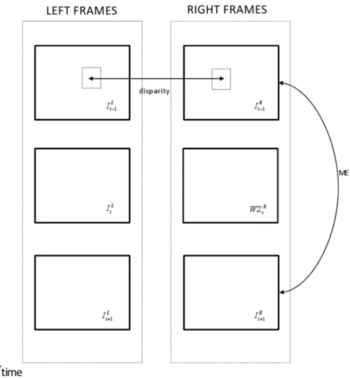
1.1 Distributed source coding. . . 6 1.2 Admissible rate ”Slepian-Wolf Region” . . . 11 1.3 Lossy compression with side information . . . 12 1.4 Stereo video coder architecture. . . 15 1.5 Turbo encoder structure . . . 19 1.6 A pseudo-random interleaver with L = 8 . . . 20 1.7 Side information creation as merging of disparity and temporal motion
es-timation for stereoscopic video sequence . . . 22 1.8 Stereo side information generation architecture using a mask-based fusion
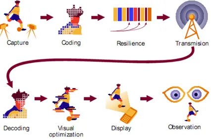
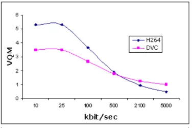
approach. . . 24 1.9 Turbo Decoder scheme. . . 25 1.10 wireless camera and monitor . . . 29 1.11 Traffic management center at Tokyo . . . 29 1.12 Document scanning with mobile phone . . . 31 1.13 Video Streaming solution over Internet . . . 32 1.14 Free viewpoint Television scheme . . . 33 2.1 Data flow of 3D TV . . . 36 2.2 Artifacts affecting various stage of 3D video delivery . . . 38 2.3 MOS scores for perceived stereo video quality. . . 48 2.4 RD performance by PSNR evaluation. PSNR is averaged on the whole right
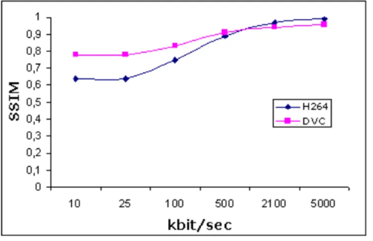
sequence. . . 49 2.6 RD performance by SSIM evaluation. SSIM is averaged on the whole right
sequence. . . 50 3.1 Channel model with uncoded side information . . . 54 3.2 The system model for Distributed Joint Source-Channel Coding . . . 56 3.3 Achievable rate region defined by Slepian-Wolf bounds . . . 57 3.4 Turbo encoder structure in DVC approach. . . 61 3.5 Turbo decoder structure in DVC approach. . . 61 3.6 parallel channel model for DJSCC scheme . . . 63 3.7 Rate-distortion comparison with different schemes. . . 64 3.8 SSIM comparison with different schemes . . . 64 3.9 RD comparisons by PSNR evaluations between our proposed method and
conventional H.264 coding. PSNR is averaged on the whole right sequence. 65 3.10 RD comparisons by SSIM evaluations between our proposed method and
conventional H.264 coding. SSIM is averaged on the whole right sequence. . 65 4.1 General scheme of multi-view distributed video acquisition . . . 68 4.2 4 different paths obtained with two H.264 cameras and two reference frames
in each H.264 cameras. . . 71 4.3 Motion estimation and disparity estimation. . . 71 4.4 fusion scheme at the decoder for [1] . . . 73 4.5 Multi-view distributed video coder architecture . . . 76 4.6 Multi-view distributed video coder architecture . . . 78 4.7 spatial side information based on homography . . . 79 4.8 Fusion scheme of side information . . . 80 4.9 RD performance by PSNR evaluation. PSNR is averaged on the whole
central camera sequence. . . 82 4.10 RD performance by SSIM evaluation. SSIM is averaged on the whole central
4.12 Multiview scheme with frame repartition. WZ frame and KF frame are alternated for each camera. . . 84 4.13 Distributed multiview video coding. . . 85 4.14 PSNR evaluations of the proposed method respect to the state of art. . . . 86 4.15 RD by SSIM evaluation. The SSIm has been averaged on the all video
sequence. . . 87 5.1 Example of MANET applications . . . 91 5.2 Mobile Ad-hoc NETwork . . . 92 5.3 Example of network composed by three main sub-layers used for simulations. 97 5.4 Comparison of the arrival time of k(1+ε) packets between network that
performs scrambling and the case where scrambling is not performed for the second step. . . 100 5.5 Comparison of the arrival time of k(1+ε) packets between network that
performs scrambling and the case where scrambling is not performed for 3A sub-network of the third step. . . 100 5.6 Comparison of the arrival time of k(1+ε) packets between network that
performs scrambling and the case where scrambling is not performed for 3B sub-network of the third step. . . 101 5.7 Comparison of the arrival time of k(1+ε) packets between network that
performs scrambling and the case where scrambling is not performed for the second step. . . 103 5.8 Comparison of the arrival time of k(1+ε) packets between network that
performs scrambling and the case where scrambling is not performed for 3A sub-network of the third step. . . 103 5.9 Comparison of the arrival time of k(1+ε) packets between network that
performs scrambling and the case where scrambling is not performed for 3B sub-network of the third step. . . 103 5.10 Arrival times comparison at different PLRs in network step 2. . . 104
5.12 Arrival times comparison at different PLRs in network 3B of the third step. 104 5.13 Comparison on arrival times for 10000 packets between network that
per-forms scrambling and the case where scrambling is not performed for the second step. . . 105 5.14 Comparison on arrival times for 10000 packets between network that
per-forms scrambling and the case where scrambling is not performed for 3A sub-network of the third step. . . 105 5.15 Comparison on arrival times for 10000 packets between network that
per-forms scrambling and the case where scrambling is not performed for 3B sub-network of the third step . . . 106 6.1 Zernike filters with order up to n = 3 and m = 3, real part and imaginary
part, respectively. . . 113 6.2 The architecture of the proposed image retrieval system. First, salient
points are extracted by means of Harris detector and a Zernike moments quadtree decomposition is applied. Then a sequential detection and esti-mation procedure is performed to retrieve the candidate image inside the database. . . 114 6.3 Example of how an image can be split in more blocks according to a quadtree
decomposition. . . 115 6.4 Example of quadtree decomposition by means of Zernike moments
compu-tation on Lena image. . . 116 6.5 In this Figure, the original image (a), the obtained neighborhoods with
Zernike expansions (b) and the reconstructed neighborhoods (c) of the salient points are shown. The size of the neighborhoods is chosen according to the quadtree decomposition. . . 118 6.6 Examples of images for each categories present in the database
COREL-1000-A. . . 126 6.7 Three database samples with different orientations . . . 136
2.1 Objective/subjective results for a low bit-rate channel. . . 51 5.1 Decoding time in the first step . . . 100 5.2 Encoding time in the second step . . . 100 5.3 Decoding time in the second step . . . 101 5.4 Encoding time for 3A in the third step . . . 101 5.5 Decoding time for 3A in the third step . . . 102 5.6 Encoding time for 3B in the third step . . . 102 5.7 Decoding time for 3B in the third step . . . 102 6.1 Performance results of the proposed method. . . 123 6.2 Average retrieval precision of the proposed ZM method compared with
con-ventional (global and regional search, color-texture, and SIMPLIcity) and recent methods (Genetic Algorithm GA). The simulations have been tested on COREL-1000-A Database. . . 124 6.3 Number of the additions and multiplications performed during the
compar-ison between the query image and the image in the DB. . . 127 6.4 Angle and scale estimate error for some images from the database . . . 135
Multimedia communication over wireless networks has generated a lot of research interests in the last years. Limited network bandwidth and the requirement of real-time playback on one hand, and severe impairments of wireless links on the other represent the main challenge. The additional issue has to do with the time-varying nature of wireless links and network heterogeneity, which make the channels between the sender and the clients extremely diverse in their available bandwidths and packet loss ratios. These diverse transmission conditions and bandwidth scarcity require an efficient scalable multimedia compression. Therefore, a robust scalable video coder is needed. Although standard video coders (e.g., H.264) can offer high coding efficiency in the scalable mode, they are very sensitive to packet loss, which results in error propagation. Motivated by its potential applications in distributed sensor networks, video coding, and compressing multi-spectral imagery, there has been a flurry of recent research activities on distributed source coding. Distributed video coding (DVC) has been proposed as a promising new technique because it adopts a completely different coding concept respect to conventional codec shifting the complexity to decoder who has the task to exploit - partly or wholly - the source statistics to achieve efficient compression. This change of paradigm also moves the encoder-decoder complexity balance, allowing the provision of efficient compression solutions with simple encoders and complex decoders. This new coding paradigm is particularly suitable for emerging applications such as wireless video cameras and wireless low-power surveillance networks, disposable video cameras, certain medical applications, sensor networks, multi-view image acquisition, networked camcorders, etc., i.e. all those devices that require low-energy or low-power consumption.
The Slepian-Wolf theorem and the Wyner-Ziv theorem state that it is possible to sepa-rately encode and jointly decode two different sources obtaining a perfect reconstruction at the decoder. The compression efficiency is comparable to conventional predictive coding systems.
Although the theoretical foundations of distributed video coding have been established in the 1970s, the design of practical DVC schemes has been proposed only in recent years. A major reason behind these latest developments is related to the evolution of channel coding, in particular Turbo and Low-Density Parity-Check (LDPC) coding, which allow to build the efficient channel codes necessary for DVC.
DVC approach can be very interesting when dealing with 3D video source both for stereoscopic video sequence and multi-view video sequence because it allows to design a simple encoder shifting all the computational complexity to the decoder. In this way, mul-tiple cameras do not need to communicate because respect to conventional codec where inter-view and intra-view prediction is accomplished at the encoder, here inter-view and intra-view data are exchanged at the decoder.
When dealing with stereoscopic sequences, it is important to take into account all the pos-sible artifacts that corrupt the coding phase. At this aim, an investigation on stereoscopic artifacts and video quality of a 3D distributed video coding system is carried out in this thesis. DVC video quality is estimated by means of subjective and objective evaluations. Then two different techniques for joint source-channel coding in distributed environments are introduced. The first is strictly related on distributed 3D video coding and it is based on turbo code. The second approach considers ad-hoc network with mobile and distributed nodes that acquire multimedia contents and exploit a joint source-channel coding system based on LT code for channel protection and information relaying.
Then, a multi-view distributed video coding system based on Zernike moments is ana-lyzed. Specifically a new fusion technique between temporal and spatial side information in Zernike Moments domain is proposed. The main goal of our work is to generate at the de-coder the side information that optimally blends temporal and interview data. Multi-view distributed coding performance strongly depends on the side information quality built at
in Zernike moments domain is applied. Spatial and temporal motion activity have been fused together to obtain the overall side-information. The proposed method will be eval-uated by rate-distortion performances for different inter-view and temporal estimation quality conditions. Finally, image retrieval techniques in multimedia database are re-ported. Two methods based on Zernike moments and Laguerre-Gauss Transform are proposed and compared with the state of art.
Distributed Video Coding
1.1
Introduction
Implementations of current video compression standards, e.g. ISO MPEG schemes or ITU-Recommendations H.26X require a more computational cost at the encoder than the decoder; typically the encoder is 5-10 times more complex than decoder. This asymme-try can be exploited in several scenarios as broadcasting or streaming video on demand systems where video is compressed once and decompressed many times. However, many systems require the opposite conditions i.e. low-complexity encoders at the expense of high-complexity decoders due to a power/processing limited systems. It is normally as-sumed that the receiver can run a more complex decoder but when the receiver is an-other complexity-constrained device, a more powerful video transcoder somewhere on the network can be used. The research developments in distributed source coding theorem suggest that efficient compression can be achieved by exploiting source statistics partially or wholly at the decoder only. These theorems are referred as Slepian-Wolf (SW) theorem for distributed lossless coding and Wyner-Ziv (WZ) theorem for distributed lossy coding with side information at the decoder. Based upon these two theorems, distributed video coding (DVC) devotes to offer the solutions for above suggested architectures. Particu-larly, Wyner-Ziv video coding, a practical case of DVC based on applying WZ theorem in real video coding has been extensively studied. The most attractive advantage of WZ video coding algorithm is that it moves the computation burden from the encoder to the
decoder but the compression efficiency still can be achieved by performing joint decoding at the decoder.
The Wyner-Ziv theory suggests that unconventional video coding system, which encodes individual frames independently but decodes them conditionally, is feasible. Such systems may achieve a performance that is closer to conventional interframe coding (MPEG) than to conventional intra-frame coding (Motion-JPEG).
Wyner-Ziv video codec has a great cost advantage because it compresses each video frame by itself, thus requiring only intraframe processing. The corresponding decoder in the fixed part of the network has to exploit the statistical dependence between frames, by much more complex interframe processing. Although numerous research achievements around WZ video coding have been made in last few years, the compression performances of WZ video coding still cannot match predictive video coding so far. DVC is still far from mature to be commercialized. There is still a wide space in the DVC field that needs to be explored in the future.
1.2
Theoretical Background
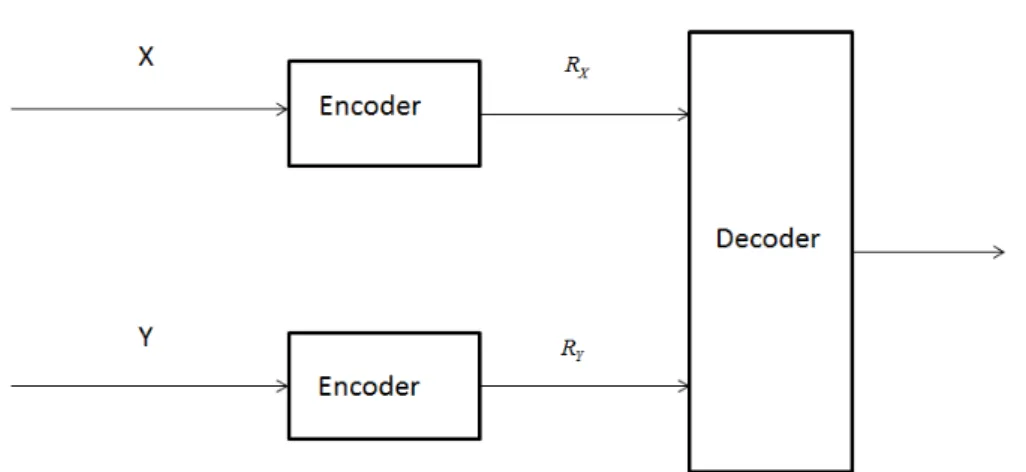
SW defined the Distributed Source Coding (DSC) problem of coding correlated sources as illustrated in Figure 1.1. Let us consider two correlated information sources that are obtained from a bivariate distribution p(x, y), [2]. Encoders for the two sources, X and
Y , operate without knowledge of the other, while the decoders have full information on
both encoded message streams. We want to determine the minimum number of bits per source character required for the two encoded message streams that assures accurate reconstruction by the decoder of the two outputs. We know that when we encode a source
X, a rate R ≥ H(X) is sufficient for accurate reconstruction of X at the decoder. Now,
suppose we deal with two sources (X, Y )∼ p(x, y), then a rate H(X, Y ) is sufficient if we are encoding them together.
Consider the scenario where X and Y have to be encoded separately. In this case, a rate
R = RX+ RY ≥ H(X) + H(Y ) is sufficient. Slepian and Wolf, however, went on to show
the decoder.
Figure 1.1: Distributed source coding.
First, let us briefly review some results for a single source that have long been known, [3]. Let X be a discrete random variable taking values in the set Γ = {1, 2, ..., Γ}. Denote the probability distribution of X by pX(x) = Pr [X = x] , x ∈ Γ. Now, let
X = (X1, X2, ..., Xn) be a sequence of n independent realizations of X so that the
proba-bility distribution for the random n-vector X is given by:
pX(x) = Pr [X = x] = n ∏ i=1 pX(xi) x = (x1, x2, ..., xn)∈ Γn, xi∈ Γ, i = 1, 2, ..., n (1.1)
X can be seen as a block of n successive characters from the output of an information
source producing characters independently with letter distribution pX(x). In a typical
long block, we have letter 1 occurring npX(1) times, letter 2 occurring npX(2) times etc.
The probability of such a long typical sequence is, therefore,
pT = pX(1)npX(1)...pX(Γ)npX(Γ)
= exp [npX(1) log pX(1)] ... exp[npX(Γ) log pX(Γ)]
= exp[−nH(X)]
where
H(X) =−
Γ
∑
i=1
pX(i) log pX(i) (1.3)
is referred as the entropy of the source X. We define these NT = exp[nH(X)] to be
the typical sequences and each of these typical sequences is equally likely and occur with probability exp[nH(X)]. Hence, we can transmit the source information over the channel with a rate R = H(X) that assures an accurate reconstruction at the decoder. This suggests that we can accurately transmit the output of the source information using only
R = (1/n) log NT = H(X) natural bits (nats) of information per character and that allows
accurate recovery of the source output.
A rate R is called admissible if for every ε > 0 there exist for some n = n(ε) an encoder
E(n,⌊exp(nR)⌋) and a decoder D(n, ⌊exp(nR)⌋) such that Pr [X∗̸= X] < ε. Otherwise R is called inadmissible.
The Slepian-Wolf theorem can now be analyzed in detail.
Theorem 1: If R > H(X), R is admissible, if R < H(X), R is inadmissible. In the
latter case, there exists a δ > 0 independent of n such that for every encoder-decoder pair E(n,⌊exp(nR)⌋), D(n, ⌊exp(nR)⌋), Pr [X∗̸= X] > δ > 0. The theorem states that for η > 0, one can achieve arbitrarily small decoding error probability with block codes transmitting at a rate R = H(X) + η; block codes using a rate R = H(X)− η cannot have arbitrarily small error probability. Hence, if the rate of the code is greater than the entropy, the probability of error is arbitrarily small and the information sequence is efficiently decoded at the receiving end.
Theorem 2: For the distributed source coding problem for the source (X, Y ) drawn
i.i.d ∼ p(x, y), an achievable rate point is given by:
RX = H(X|Y ) + εx, εx > 0 RY = H(Y ) + εy, εy > 0
(1.4) The feasibility of the rates in the Slepian-Wolf theorem can be proofed introducing a new coding theorem based on random bins. The underlying idea regarding these random bins is very similar to hash functions,i.e., we choose a large random index for each source sequence. If the number of these typical sequences is small enough, then with high prob-ability, different source sequences will have different indices, and we can reconstruct the
source sequence from the index.
The procedure for the random binning follows these rules: for each sequence Xn, an index randomly chosen from {1, 2, ..., 2nR} is given. The set of sequences that have the same index forms a bin. For decoding the source from the bin index, we look for a typical Xn sequence in the bin. If there is one and only one typical sequence in the bin, we declare it to be the estimate of the source sequence; otherwise, there is an error. In practice, if there is more than one typical sequence in this bin, an error is present. If the source sequence is non-typical, then there will always be an error. The probability of error is arbitrarily small for sufficient R.
Consider the encoding and decoding problem for a single source. The proof for the above coding scheme producing an arbitrarily small probability of error for R > H(X) is as follows: Pe(n)= P [g(X) = X] = P [ (X /∈ A(n)ε )∪ (f(X′) = f (X); (X′, X)∈ A(n)ε , X′ ̸= X) ] ≤ P[X /∈ A(n)ε ] +∑ x P [ ∃x′̸= x : x′ ∈ A(n) ε , f (x′) = f (x) ] p(x) ≤ ε +∑ x ∑ x′∈A(n)ε ,x′̸=x P (f (x′) = f (x))p(x) = ε + ∑ x′∈A(n)ε 2−nR∑ x p(x) ≤ ε + 2−nR2n(H(X)+ε) ≤ 2ε (1.5)
The basic idea of the proof is to partition the space of Xninto 2nRX bins and the space
of Υninto 2nRY bins.
Random code generation: Independently assign every x ∈ Xn to one of 2nRX bins
according to a uniform distribution on {1, 2, ..., 2nRX}. Similarly, randomly assign every
y∈ Υnto one of 2nRY bins. f
1 and f2 are assigned to both the encoders and the decoder.
Encoding: Source 1 sends the index of the bin to which X belongs and source 2 sends
the index of the bin to which Υ belongs.
one pair of sequences (xy) such that f1(x) = i0, f2(y) = j0 and (x, y) ∈ A(n)ε . Otherwise,
declare an error.
The set of X sequences and the set of Y sequences are divided into bins such a way that the pair of indices specifies a product bin. Having done this, the probability of error at the decoder is defined as the union of the following events:
E0 = { (X, Y ) /∈ A(n)ε } E1 = { ∃x′ ̸= X : f1(x′) = f1(X)and(x′, Y )∈ A(n) ε } E2 = { ∃y′̸= Y : f 2(y′) = f2(Y )and(X, y′)∈ A(n)ε } E3 = { ∃(x′, y′) : x′ ̸= X, y′ ̸= Y, f1(x′) = f1(X), f2(y′) = f2(Y )and(x′, Y )∈ A(n) ε } (1.6) Thus Pe(n)= P (E0∪ E1∪ E2∪ E3) ≤ P (E0) + P (E1) + P (E2) + P (E3) (1.7) Extending the result for a single source to two sources, we can say that the cardinality of the set of jointly atypical sequences (xy) is very small compared to that of the jointly typical sequences. It follows that the probability measure of that set → 0 for large n. Hence,
P (E0) = ε
Now lets consider P (E1),
P [E1/(X = x, Y = y)] = ∪ (x′,y)∈A(n)ε ,(x′=x) { f1(x′) = f1(x) } Thus, P [E1] = ∑ (x′,y′) p(x, y)P [E1/(X = x, Y = y)] ≤ ∑ (x,y) p(x, y)· ∑ (x′,y)∈A(n)ε ,(x′̸=x) P [f1(x′) = f1(x)] ≤ ∑ (x,y)
p(x, y)2−nRX|Aε(X/y)|
≤ 2−nRX2n(H(X/Y )+ε)
(1.8)
which→ 0 if RX > H(X|Y ) and n is large. The above result follows from the following: P[f1(x′) = f1(x)/ (f1(x) = i0)
]
This implies that, P [f1(x′) = f1(x)] = ∑ i0 P [(f1(x) = i0)]· P [f1(x′) = f1(x)/ (f1(x) = i0)] = 2−nRX·∑ i0 P [f1(x) = i0] = 2−nRX (1.9)
|Aε(X/y)| is defined to be the set of X sequences that are jointly typical with a particular Y sequence. The proof for the fact that|Aε(X/y)| ≤ 2n(H(X/Y )+2ε)is as follows,
1≥ ∑ x∈A(n)ε (X/Y ) p(X/Y ) ≥ ∑ x∈A(n)ε (X/Y ) 2−n(H(X/Y )+2ε) = A(n)ε (X/Y ) 2−n(H(X/Y )+2ε) Thus we have, A(n) ε (X/Y ) ≤ 2n(H(X/Y )+2ε)
When dealing with large values of n and high rates, the probabilities of the events
E2 and E3 get arbitrarily small. It follows from the above discussion that the overall
probability of error for the joint sequence at the decoder is,
Pe(n)≤ 4ε
which is arbitrarily small. It can, therefore, be seen that the condition for achievability of the rate pair has been satisfied by (RX, RY) = (H(X/Y ) + εx, H(Y ) + εy). Hence, this is
the proof for the theorem.
The rate pair that has been suggested above can change roles i.e, we can have (RX, RY) =
(H(X) + εx, H(Y /X) + εy) and the theorem would still hold. This is equivalent to saying
that the decoder now has complete information about the source and is trying to decode Y based on the joint typical sequence set. Thus, the rate region can be expressed as,
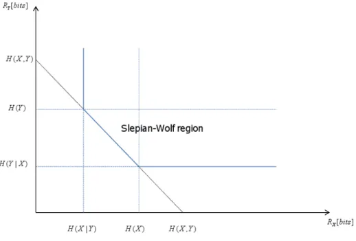
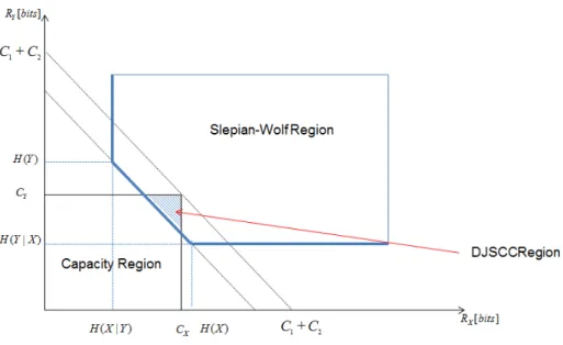
RX ≥ H(X|Y ), RY ≥ H(Y |X) RX+ RY ≥ H(X, Y ).
(1.10) Despite the separate encoding of X and Y , SW proves that the total rate ,RX+ RY , for
Figure 1.2: Admissible rate ”Slepian-Wolf Region”
According to the Slepian-Wolf theorem and equation 1.10, the rate region, called ”Slepian-Wolf region”, for the reconstruction with an arbitrary small error probability of X and Y can be described by Fig. 1.2, where the vertical, horizontal and diagonal lines, corresponding to those three formulas of equation 1.10 respectively, represent the lower bounds for the achievable rate combinations of R(X) and R(Y ). Slepian-Wolf coding generally refers to the lossless distributed source coding. Notice that lossless here is not mathematically lossless but allowing a controlled amount of errors which is approaching the lossless case. One interesting feature of Slepian-Wolf coding is that it is a close kin to channel coding which was already studied by Wyner. Considering two i.i.d. binary sequences X and Y and a virtual correlation channel, the source sequence X and side information sequence Y are modeled as the input and output of the virtual channel re-spectively. Y is therefore a noisy version of X where noise introduced by the channel refers to the correlation between X and Y . Then a systematic channel code can be adopted to encode X and only the resulting parity bits are transmitted. At the decoder, the received parity bits and the side information Y are used to perform error-correcting decoding. In this approach, significant compression is resulted due to the fact that only few parity bits
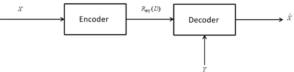
Figure 1.3: Lossy compression with side information are needed to be sent.
1.2.1 Wyner-Ziv theorem
Later on, Wyner and Ziv studied the counterpart of SW theorem for lossy coding and established the bounds for lossy compression with side information at the decoder,[4], where the decoder produces ˆX with a certain distortion D with respect to X as illustrated
in Figure 1.3.
When the SI is available at both, encoder and decoder sides, a rate RX|Y(D) is achieved
for encoding X with a distortion D. Further, there is an increase of (RXW Z|Y(D)−RX|Y(D)) = 0 in rate when the SI is not available at the encoder but only at the decoder side. In other words, the rate in the case where the SI is not available at the encoder is lower bounded by the one when the SI is available at the encoder. However, Wyner and Ziv show that both rates, RW ZX|Y(D) and RX|Y(D), are equal when the sources are memoryless Gaussian and the Mean Square Error (MSE) is used as the distortion metric. With a predefined threshold D, they established the minimum rate necessary to encode X guaranteeing ˆX
with an average distortion below D. The results indicated that for the same threshold D, the minimum encoding rate (for X) of the case when the statistical dependency between
X and Y is only available at the decoder, described by RW Z(D), is bigger than that of
the case when the dependency is available both at the encoder and the decoder, described by RX|Y(D). The Wyner and Ziv theorem also can be described by Eq.1.11:
In the literature, RW Z(D) and RX|Y(D) are called Rate-Distortion (RD) functions.
No-tice that when D = 0, equation 1.11 falls to the Slepian-Wolf result which means that it is possible to reconstruct X with an arbitrarily small error probability even when the correlation between X and Y is only available at the decoder.
Finally, the Slepian-Wolf theorem and the Wyner-Ziv theorem state that is possible com-pressing two statistically dependent sequences in a distributed way (separate encoding, jointly decoding); the difference between them is that in the Slepian-Wolf theorem the de-pendency between two sequences is available both at the encoder and the decoder therefore the coding is lossless with allowing an arbitrary small error probability between the source sequence and the reconstructed sequence, while in the Wyner-Ziv theorem the dependency is only available at the decoder and sequences are lossy coded.
1.3
State of Art
Distributed Video Coding (DVC) states that it is theoretically possible to separately encode and joint decode two or more statistically dependent sources at the same rate obtained when the same sources are joint encoded and decoded, [4][2]. This strategy has been adopted by many authors for the design of high compression rate inter-frame video coding schemes. The common goal is to generate at the decoder a side information that optimally blends temporal and interview data. In other terms, while standard video coders exploit the statistical dependencies of the source signal in order to remove spatial and temporal redundancies, in DVC each video frame is encoded independently, knowing that some side information will be available at the decoder to remove transmission errors and improve the video quality. This approach considerably reduces the overall amount of transmission necessary from the cameras to the central decoder and simplifies the com-plexity of the video encoder by shifting all the complex interframe processing tasks to the decoder. This property can be very interesting for power/processing limited systems such as wireless camera sensors that have to compress and send video to a fixed base station in a power-efficient way. It is normally assumed that the receiver can run a more complex decoder but when the receiver is another complexity-constrained device, a more powerful
video transcoder somewhere on the network can be used.
However, although all these approaches are extremely promising, they are still not as efficient as standard video coders in terms of rate-distortion performance due to the fact that distributed source coding techniques rely on a a-priori knowledge of the correlation structure. These approaches are often not simple in practical applications as asymmetric: in fact some cameras need to transmit their full information to provide side information to the decoder while others only transmit partial information. Finally most of the multi-view DVC approaches do not take advantage of the multi-multi-view geometry to improve the performance of their encoders.
The first attempts to design quantizer for reconstruction with side information were inspired by the information theoretic proofs. Zamir and Shamai , [5], proved that, under certain constraints, linear codes and nested lattices may reach Wyner-Ziv rate-distortion function when source data and side information are jointly Gaussian. This idea has been elaborated and applied by Pradhan et al., [6], who studied both the asymmetric case of source coding with side information at the decoder for Gaussian sources that are statisti-cally dependant and the symmetric case where both sources are encoded at the same rate. Xiong et al., [7] implemented instead a nested lattice quantizer as WZ encoder, followed by a SW coder and proved that Low-Density-Parity-Code (LDPC) can be a powerful solution for DVC.
Yeo and Ramchandran [8] proposed a robust method that exploits inter-view correla-tion among cameras that have overlapping views in order to deliver error-resilient video in a distributed multiple wireless camera sensors scenario. The system has low encoding complexity, satisfies tight latency constraints, and requires no inter-sensor communica-tion. Each video frame is divided into non-overlapping blocks and the syndrome of each quantized block is transmitted with a cyclic redundancy check (CRC) computed on the quantized block. The encoder at each of the video camera sensors does not need any knowledge about the relative positions of any other cameras. The decoder searches over candidate predictors and attempts to decode using the received syndrome and the can-didate predictor as side-information. If the CRC of the decoded sequence checks out, decoding is assumed to be successful. In particular, the decoder first tries to decode a
block using decoder motion search in the temporal dimension; if that fails, then decoder performs the disparity search along the epipolar line in each overlapping camera view.
In [9] the authors propose a practical solution for Wyner-Ziv stereo coding that avoids any communication between the low complexity encoders. The method is based on a pixel-level mask fusion of temporal and interview side information. In particular, the first view is coded in conventional way using H.264/AVC, and DVC principles are applied to the coding of the second, dependent view. The system fuses, pixel-by-pixel, the temporal side information created using a motion-based frame interpolation scheme with the interview side information created using a disparity-based frame extrapolation algorithm. This technique shows the potential of a side information fusion approach performed at the decoding stage. The same approach is followed in [10], where the authors adaptively select either the temporal or the interview side information on a pixel by pixel basis. The system uses also a turbo decoder to detect when decoding is successful and no more parity bits need to be requested via the feedback channel. The proposed algorithm has the advantage to be symmetric with respect to the two cameras.
1.4
The Considered DVC Architecture
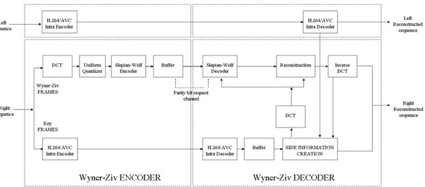
The considered practical DVC architecture used in this research follows Pereira approach, [9], and it is shown in Figure 1.4.
This codec is an evolution of the one initially proposed in [11] and uses a feedback channel based turbo coding approach.
The DVC encoding architecture works as follows: a video sequence is divided into Wyner-Ziv (WZ) frames and key frames. The key frames may be inserted periodically with a certain Group of Pictures (GOP) size or an adaptive GOP size selection process may be used depending on the amount of temporal correlation in the video sequence; most results available in the literature use a GOP of 2 which means that odd and even frames are key frames and WZ frames, respectively. While the key frames are conventionally encoded with video codec such as AVC/H.264 Intra; the WZ frames are DCT transformed and then quantized,[12]. Then, the quantized coefficients are split into bit planes, and one by one are turbo encoded. The reason of the this choice lies in near-channel capacity error correcting capability of the turbo code. The parity bits are stored in the buffer and transmitted in small amounts upon decoder request via the feedback channel.
At the decoder, the frame interpolation module is used to generate the side information frame, an estimate of the WZ frame Xi, based on previously decoded frames, Xi−1 and Xi+1. The side information is treated as noisy corrupted version of coded WZ frame and
used to decode the coded WZ frames at the decoder. For a Group Of Pictures (GOP) length of 2, Xi−1 and Xi+1are the previous and the next temporally adjacent key frames,
Intra coded. The side information (SI) is then fed by an iterative turbo decoder to obtain the decoded quantized symbol stream. The decoder requests for more parity bits from the encoder via the feedback channel whenever the adopted request stopping criteria has not been fulfilled; otherwise, the bitplane turbo decoding task is considered successful. The side information, together with the decoded quantized symbol stream, is also used in the reconstruction module. After all DCT coefficients bands are reconstructed, a block-based 4x4 inverse discrete cosine transform (IDCT) is performed and the result is the reconstructed WZ frame. To finally get the decoded video sequence, decoded key frames and WZ frames are conveniently merged. The statistic dependency between the original WZ frame Xi and the side information Yi is modeled as Laplacian distribution. When Yi,
received parity bits and derived Laplacian distribution parameters, is obtained then it is possible to turbo decode and then reconstruct the quantized symbols.
When dealing with stereo sequence, there are two dependent views to be coded. In a Wyner-Ziv coding framework, the available statistical dependency has to be exploited not only in time as was done for the monoview case, but also in space, i.e. between the two dependent views.
1.4.1 Transformation
The aim of the transformation phase is to make the input video more suitable for com-pression by compacting the signals energy into the lower transform coefficients. The DVC scheme uses the 4x4 separable integer transform in AVC/H.264 with properties similar to the DCT. Given a N xM frame, the DCT transform is defined as follows, Equation 1.12:
XDCT[u, v] = 4 N xMc[u]c[v] N∑−1 n=0 M∑−1 m=0 x[n, m] cos [ (2n + 1)uπ 2N ] cos [ (2m + 1)vπ 2M ] (1.12) where XDCT[u, v] , for u = 0, 1, ..., N − 1 and m = 0, 1, ..., M − 1 represents the DCT
coefficient at (u, v), i.e., line (row, vertical axis) u and column (horizontal axis) v, and:
c[u], c[v] = 1 √ 2, foru, v = 0 1, otherwise
The first cosine term is the vertical basis function generator represented by sampled cosine signal. n sets the sample number and u sets the frequency. For the same reason, the second cosine term is followed as the horizontal basis function generator. Since the DCT is separable, the two-dimensional DCT can be obtained by computing 1-D DCT in each dimension separately. For the implementation view point, most of international standards favor 4x4 block size, considering its complexity and performance. It converts the image block into a form where redundancy or correlation in the image data is reordered in terms of the basis images, so that the redundancy can be easily detected and removed. The detection is possible by the virtue of orthogonal property of the basis images; non-zero coefficients are obtained if an image pattern block coincides with the basis block. Natural image data, of course, may not coincide with the rectangular shaped basis images. Although the DCT shows sufficient performance of compression capability, one major disadvantage of the DCT is the block structure that dominates at very low bit rates, called blocking artifacts transforms. If the difference of quantization errors between two
adjacent blocks is so large, it would be easily detectable by human eye and the block disparity occurs.
1.4.2 Quantization
In general, a Wyner-Ziv coder can be thought as consists of a quantizer followed by a Slepian-Wolf encoder. Quantization of the sampled data is performed with a finite number of levels. It is assumed that the sampling is uniform and sampling rate is above the Nyquist rate so that there is no aliasing in the frequency domain. Some criteria, such as minimization of the quantizer distortion, have been used for quantization of image data. Quantizer design includes input (decision) levels, output (representation) levels and the number of levels. A uniform quantizer is completely defined by the number of levels, step size and if it is a midriser or a midtreader. Instead of the type of quantizers, a quantized output (reconstruction) value is determined in a certain interval (quantization step) where any of the input values happens. Since the reconstruction value represents the whole range of input values, quantization inherently is a lossy process and the lost information may not be recovered. Since, usually, the distribution of image data is concentrated on mean value region and image processing, including predictive coding and transform coding, produces more abundant distribution on smaller levels near zero, which means less energy or variance, the region can be quantized with fine step size, while others can be quantized with coarse step size. A nearly uniform quantizer is designed using these properties, enlarging the step size only in the mean value region, called a deadzone. Except for the deadzone (input range for which the output is zero), the stepsize is constant.
1.4.3 Slepian-Wolf Encoder
The Slepian-Wolf codec can be implemented by a systematic channel code as turbo code. This coding technique consists essentially of a parallel concatenation of two binary con-volutional codes, decoded by an iterative decoding algorithm. These codes obtain an excellent bit error rate (BER) performance by making use of three main components, [13]. A turbo encoder is constructed using two RSC (Recursive Systematic Convolutional) en-coders arranged in parallel and combined with a random interleaver, together with a
Figure 1.5: Turbo encoder structure
multiplexing and a puncturing block. Typically, the two encoders E1 and E2 are RSC
encoders of rate Rc = 1/2, such that c′1 = c1, c′2 = c2 and the lengths of the incoming
sequences m, c1 and c2, and c′1 and c′2 are all the same. Then the overall turbo code rate
is Rc = 1/3. Puncturing is a technique very commonly used to improve the overall rate
of the code. It consists in periodically eliminating one or more of the outputs generated by the constituent RSC encoders. Thus, for instance, the parity bits generated by these two encoders can be alternately eliminated so that the redundant bit of the first encoder is first transmitted, eliminating that of the second decoder, and in the following time in-stant the redundant bit of the second encoder is transmitted, eliminating that of the first. Puncturing is not usually applied to the message (systematic) bits, because this causes a BER performance loss. In this way, the lengths of c′1 and c′2 are half the lengths of c1
and c2, respectively, and the resulting overall rate becomes Rc= 1/2. Puncturing is not
usually applied to the message (systematic) bits, because this causes a BER performance loss. There are two important components of a turbo encoder whose parameters have a major influence on the BER performance of a turbo code: the first is the interleaver, espe-cially its length and structure, and the second is the use of RSC as constituent encoders. The interleaver reads the bits in a pseudo-random order. The choice of the interleaver is a crucial part in the turbo code design in fact the task of the interleaver is to ”scramble” bits in a (pseudo-)random. Two are the purposes. Firstly, if the input to the second encoder is interleaved, its output is usually quite different from the output of the first encoder. This