i
a.a. 2007/2010
Università degli Studi di Catania
Scuola Superiore di Catania
International PhD
in
Energy
XXIII cycle
Energy Storage in Electric Power Generation
Plant from Renewable Sources
Tommaso Scimone
Coordinator of PhD
Tutor
Prof. Alfio Consoli
Prof. Antonio Testa
ii
During last years the utilization of renewable energy resources has received considerable attention because of the adverse environmental impacts and cost escalation of conventional fuel generation plants. Solar photovoltaic and wind energy industries are two sectors very rapidly growing, and both of them are attracting investments of billions of dollars. However, photovoltaic and wind, like most of the renewable energy sources are characterized by high variability and discontinuity. The high unpredictability of the primary resource makes diffi-cult to forecast the energy production. This is a major trouble for network utility grid management and for the final user, especially in the case of systems operated in island mode. Application of high efficiency energy storage techniques could stimulate in a near future a larger exploitation of renewable energy sources. Energy storage, in fact, could not only improve the quality of the produced power, but, it could also make possible the implementa-tion of sophisticated energy management strategies, fully decoupling the power delivery from power generation.
iii
This work has been done in collaboration with the Scuola superiore of catania and Isab Energy of Priolo Gargallo – Siracusa. Acknowledgements are given to afore mentioned institutions for their financial support.
The research activity was carried out under the supervision of my Tutor Professor Antonio Testa from the Dipartimento di Chimica Industriale ed Ingegneria dei Materiali (DCIIM) at Messina University. I would like to express my sincere gratitude to my Tutor for his invalua-ble guidance, encouragement and support throughout the period of my PhD studies. I would also like to thank the Coordinator of PhD, Prof Alfio Consoli, for his support and professional guidance.
I would like to express my sincere thanks to Dr. Luigi Iannitti and Dr. Alberto Rabuazzo from Isab Energy, for their help and support and for their useful discussions.
I’m also grateful to Salvatore De Caro from the University of Catania for his active support and friendship.
I would also like to thank my colleagues Santo Bivona, Vittorio Crisafulli and Marzia Pap-palardo who have always supported and encouraged me during these years.
And, last but not least, I would like to express my immense gratitude to my family for their continued support and assistance during the course of these years.
iv Abstract ... ii Acknowledgments ... iii Table of contents ... iv Chapter 1 Introduction ... 1 1.1 Introduction ... 1
1.2 Objectives and motivations ... 5
1.3 Main Activities ... 6
1.4 Scientific production ... 9
1.5 Attended Conferences ... 10
Chapter 2 Energy Storage System and Renewable Energy Sources ... 11
2.1 Classification of Energy storage technologies ... 11
2.1.1 Hydroelectric storage system ... 13
2.1.2 Thermodynamic accumulation ... 13
2.1.3 SMES and Flywheels ... 14
2.1.4 Batteries ... 14
2.1.5 Fuel-Cells + Electrolyser ... 16
2.1.6 Regenerative fuel-cells ... 19
2.1.7 Flow batteries ... 19
2.1.8 Supercapacitors ... 21
2.2 Renewable energy sources – Overview ... 23
2.2.1 Geothermal energy ... 23
2.2.2 Hydroelectric Energy ... 25
2.2.3 Energy from the sea ... 26
2.2.4 Biomass energy ... 27
2.2.5 Solar energy ... 28
2.2.6 Wind energy ... 30
Chapter 3 Design criteria for energy storage devices for distributed generations system ... 32
3.1 Introduction ... 32
3.2 Analysis of technical literature – Overview ... 33
3.3 Loss of Power Supply Probability (L.P.S.P.) ... 36
Chapter 4 A VRB energy storage system for a tidal turbine generator ... 40
4.1 Introduction ... 40
4.2 Tidal turbine generator prototype ... 41
4.3 VRB- ESS design ... 44
4.4 Conclusions ... 51
Chapter 5 Optimal Design of Energy Storage Systems for Stand-Alone Hybrid Wind/PV Generators... 53
5.1 Introduction ... 53
v
5.4 Hybrid generation system sizing ... 59
5.5 Cost Analysis ... 66
5.6 Conclusions ... 68
Chapter 6 Sizing and stability assessment of grid connected large photovoltaic plants including energy storage systems ... 69
6.1 Introduction ... 69
6.2 Power conversion system for conventional PV plants ... 71
6.2.1 Energy losses due to transformer overloads ... 72
6.2.2 Energy losses due to transformer efficiency ... 74
6.2.3 Energy losses due to grid instability ... 74
6.2.4 Transformer size selection ... 75
6.3 Transformers for PV plants with energy storage ... 77
6.3.1 Energy losses due to transformer overloads ... 77
6.3.2 Energy losses due to transformer efficiency and grid instability ... 78
6.3.3 Transformer size selection ... 79
6.4 Conclusions ... 84
Chapter 7 A VRB ESS for a large Turbogas Power Plant ... 85
7.1 Introduction ... 85
7.2 Day Before Market (MGP) ... 86
7.3 Proposed Approach ... 87
7.4 Simulations results ... 88
7.5 Conclusions ... 93
Conclusions ... 95
1
Chapter 1
Introduction
1.1 Introduction
The availability of fossil fuels has had a crucial role in the development of the modern civilization in the last two centuries. However, the raise of primary energy request caused by the demographic growth in developing countries and by an energy starving style of life in developed countries, will lead to an unsustain able situation in the near future, due to the limited fossil fuel reserves still available. From the oil crisis of the early 70s to date, the progressive exhaustion of the traditional energy sources had become, a major awareness. Therefore, studies and researches oriented to a broader exploitation of renewable energy sources are powered, as a response to difficulties today experienced in industrialized countries in primary energy procur e-ment. Moreover, renewable energy sources represent a quite viable solution to the worrisome increase of air pollution, because of their zero or very low emissions. Among renewable energy technologies, those of photovoltaic cells and wind tu r-bines are indeed the most popular, both featuring no pollution and being advantaged by a large availability of an inexpensive primary energy. In the past, their diffusion was limited by technological shortcomings and higher costs if compared with traditional generation techniques. However, thanks to the technological progresses of the last two decades the efficiency and reliability of photovoltaic and wind generators have been improved while the costs have been noticeably lowered. Although a full commercial competitiveness with conventional systems today is not still reached, potential benefits of large scale production and the c onstant raise of the
2
cost of fossil fuels could result in an acceptable level of competitiveness in a short time.
As can be seen in Figure 1.1, a rapidly growing use of renewable sources (mainly wind) is today experienced. Furthermore, until 2004, nearly 50% of energy world-wide obtained from renewable sources has been produced in Japan, which is still the world leader in manufacturing and installation of photovoltaic systems. The country that has most encouraged the exploitation of renewable energies in Eur ope, is Germany, although Spain and Denmark are remarkably recovering. In these coun-tries noticeable changes were made to traditional electric energy generation and management strategies, also exploiting conventional and innovative storage techno l-ogies. According to the forecasts of the European Union the incidence of the renewable sources on the whole continental electric energy production should reach a 20% within the 2020. In some regions, more suitable where will be able to overcome even the 50%.
Figure 1.1 - Impact of the renewable in the world
Figure 1.2 shows the worldwide projected increase of energy production from renewable sources. In the view of growing public support and government ince n-tives ,in the future years an increase in rated power installed from renewable sources installed higher than estimated expectations can be expected.
3
In Italy, thanks to the significant contribution of government incentives, some renewable sources reached very encouraging developments. The new photovoltaic capacity installed in only 2009 (574 MWp) was far higher than total quantity i n-stalled until the previous year (458 MWp), exceeding the threshold of 1 GWP. For wind energy, Italy is the third country in Europe in 2009, both for new installed capacity (1,113 MW) that for total installed power (4850 MW).
Figure 1.2 - Estimated growth of energy production from renewable sources in the world
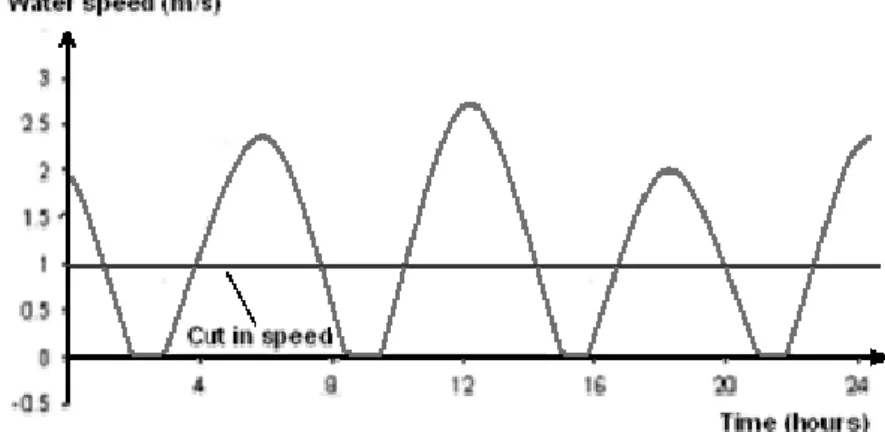
The effective power availability from a renewable energy source depends on the variation of the primary resource over the time, which show seasonal, daily or instantaneous dynamics. The wind undoubtedly is the renewable energy source that more than the others suffers from the variability. As shown in Figure 1.3, it is generally impossible to determine exactly the daily production of a wind farm. In particular it can be seen that variations of the wind speed, results in noticeable fluctuations of the output power. Photovoltaic plants are also heavily influenced by weather conditions, moreover, they feature a limited period of operation over the day. The non fossil source that show the lower variability is the geothermal energy, whose exploitation is however possible only in few areas.
4
Because of the unpredictable availability of power photovoltaic panels and wind turbines cannot ensure the minimum level of power continuity required to supply a generic network of electrical loads. Therefore, they must be integrated with energy storage devices and/or auxiliary generators, in order to decouple the energy gener a-tion from the delivery [1].
Moreover, a distinction must be made between “island” mode of operation, where the generator operates disconnected from the main network and “grid connected” mode of operation, where the generator is permanently connected to the main network. In fact, while in the last case the stability is theoretically guaranteed by the power prevalence of the main network, particularly critical is the first oper a-tion mode, as a suitable accumulaa-tion system is mandatory to balance the differences between the available primary power and the requested load power.
Figure 1.3 - Percentage course of the power in exit from a wind turbine
The stability of the Italian national network is ensured by interaction between a core of fossil fuel (natural gas, oil and coal) generation plants, providing the base power, and a set of peak power generation plants (hydro and gas turbine) distributed throughout the country, supporting rapid load changes. In the rest of the Europe the scenery is different for the presence in some countries of nuclear power stations, that, on one hand guarantee a substantial portion of the basic power but, on the other hand, require complex energy management strategies. Traditional electric systems are however not able to support the expected rapid proliferation of renewable energy generation plants, at least without introducing new management strategies and
5
accumulation plants. In fact, the power generated by wind farms today is limited to 15% of the total power distributed through the network in order to ensure stability. This claims for the introduction of suitable accumulation systems in association with the activation of further generation plants from renewable sources.
In the perspective of a broad use of renewable energy generators and therefore of a proliferation of large size accumulation systems, cost, reliability and durability of these systems could significantly affect the economy and reliability of national electricity system.
1.2 Objectives and motivations
The optimal sizing of energy storage systems for generation plants from renew-able sources is an extremely complex task, that requires an interdisciplinary knowledge and suitable computation and simulation tools. Moreover, standard rules have not be defined and universally accepted until now. Therefore, the design is mainly performed case by case, exploiting the available know-how and the accessi-ble technologies.
The main objective of the work is to develop general design rules for the accumu-lation system, accounting for the specific features of the renewable energy source generation system, the grid connection and the load time diagram.
In order to develop such rules it is first necessary to build a suitable mathematical model of the system and to identify mathematical relationships describing the interaction among the different elements of the system, the interaction between the system and the primary energy source and the interaction between the system and the grid.
This lead to analyse:
• on the availability and variability of the different renewable energy sources; • on energetic and dynamical features of generation systems;
• on output power, energy, and response features of accumulation systems; • on typical load diagrams of the considered applications;
• on control and management strategies of the generation and accumulation systems;
6
• on the environmental impact, especially in terms of required space and use of potentially dangerous materials.
1.3 Main Activities
In the first year of my PhD course main attention was focused on the acquisition of a basic theoretical knowledge of energy transformation, energy conversion and energy storage. During this year, I attended three academic courses and several seminaries concerning different topics in the area of the energy.
In this first year my research activity has been primarily focused on some aspects of the distributed generation. Distributed generation systems can offer increased reliability, uninterrupted service while lowering energy costs. Different electric power generators, such as: Fuel-cells, microturbines, wind turbines, or photo-voltaic cell arrays are today considered to be introduced in distributed systems. These devices generate a DC voltage that must be converted into an AC voltage, suitable for residential or industrial use through DC/AC converters (inverters). A key feature of conventional inverters is that the peak AC output voltage is always lower than the input DC voltage. Therefore, when a peak AC output voltage larger than the DC input voltage is required, a further DC-DC boost converter must be inserted between the voltage source and the inverter.
At the end of the first year, a two years long research project was defined with Dr. Iannitti of the ERG firm and Prof. Testa to study storage devices aimed to equip generation systems from renewable energy sources. This project, called "Energy Storage in Generation Systems from Renewable Sources" started from an evaluation of the energy storage technologies scenario and possible applications of available devices. The discontinuity of renewable energy sources and the problems related to the sizing of storage system have been then accounted. A special emphasis was placed on VRB-ESS and Electrolyzer + Fuel cell systems.
In the second year of my PhD course the attention was focused on the develop-ment of design tools to accomplish an optimal sizing of hybrid generation systems including energy storage devices.
Available energy storage devices differ in terms of specific power, energy cap a-bility, cost and maturity. Therefore, the design of energy storage systems is a
7
complex task, which requires an interdisciplinary knowledge and suitable comput a-tion and simulaa-tion tools. The complexity of the task is also increased by the possibility to combine together different technologies in order to satisfy the specifi-cations in terms of power density, storage capability and cost.
The first step to accomplish along the design of an energy storage device is to evaluate the effects of input power variations on the loads through accurate m odels. Suitable mathematical tools, able to analyse the dynamic behaviour of generation systems and storage devices, are then required to determine the storage technology and the storage capacity that best fit the load requirements. The development of these tools has been the objective of the second year activity that will be reported in the following sections, together with a brief overview of two papers presented at the EPE 2009 Conference held in Barcelona Spain in September 2009.
Another project was started in co-operation with CNR-ITAE of Messina. The aim of this work was a comparative evaluation of some regenerative energy storage technologies, specifically VRB-ESS and Fuel Cell + Electrolyzer systems. The set of parameters to be compared includes: reliability, availability and the ability to per-form maintenance work in a fast, effective and easy way.
In November 2009 I attended a course on Energy Management at LIUC Univers i-ty of Castellanza (VA). This course provided a comprehensive view of energy issues, with particular interest in the audit of the utilities and economic and produ c-tive assessments of renewable energies, especially photovoltaic. The kwon -how assumed during this course has been particularly useful for the activities of the third year.
In the third year of my PhD the attention was focused on grid connected gener a-tion systems exploiting renewable sources. The aim was the development of a general methodology to accomplish an optimal sizing of the power conversion system in PV plants either directly delivering power to the utility network, either equipped with energy storage systems. A new probabilistic approach has been developed starting from the basic L.P.S.P. index. The methodology is very simple and adaptable to different applications. Moreover the proposed approach provides a very interesting way to solve problems related to the discontinuous delivery of power to the utility network. This may result in frequent plant shutdowns, while requiring a remarkable reserve power to be provided by conventional generation
8
systems. The proposed approach has been described in a paper presented at the ICEM 2010 Conference held in Rome, Italy, last September.
During the third year of my PhD a new co-operation with CNR ITAE regarding the sizing of stand-alone generation systems was also started. The aim of this co-operation was the realization of a software tool able to calculate the minimum size of the generation and storage system able to satisfy a given set of loads. This stand alone tool has been entirely realized in MATLAB. The software simulates the behavior of four types of storage systems (Vanadium Redox Batteries, Lead Acid Batteries , Li - ION, Fuel cell + Electrolyzer), considering some different renewable energy generation plants (solar, wind and hybrids). The accomplished analysis allows to estimate the initial cost of the system (considering the average costs of photovoltaic modules per m2 and the average cost of wind turbines per kW) and the plant life cost. It is then possible to compare the cost of different configurations of the storage system in terms of kWh and kW. Two papers were published on this topic in co-operation with CNR ITAE, both presented at the SPEEDAM Conference held in Pisa, Italy, in June 2010.
In the context of the PhD course a further project was started in co-operation with Dr. Iannitti and Dr. Rabuazzo of Isab Energy. This project regards the application of electrochemical energy storage systems to a conventional Turbogas Generator (TG) in Priolo (SR). During daylight hours the plant has an almost constant operating rate, close to the point of maximum efficiency of the TG. On the contrary, overnight (from 10.00 pm to 7.00 am), the TG group needs to work at reduced power, leading to a reduction in efficiency as well as a lower gain. The aim of this work is the design of a suitable VRB energy storage system able to store all the surplus of energy produced during the night. This amount of energy is usually sold to the grid at very low price. Introducing an energy storage system this amount of energy can be stored during the night and then delivered during the day when the price of the energy on the market (MGP) is much higher
9
1.4 Scientific production
“Analysis of a VRB energy storage system for a tidal turbine generator” A. Testa, S. De Caro, T. Scimone - European Conference on Power electron-ics and applications (EPE 2009), 8-10 September, Barcelona, Spain.
“High efficiency field oriented control of an induction generator for a tidal current turbine”
A. Testa, S. De Caro, T. Scimone - European Conference on Power electron-ics and applications (EPE 2009), 8-10 September, Barcelona, Spain.
“A solar AC module with active filter capabilities”
Testa, A.; Scimone, T.; De Caro, S.- International Symposium on Power Electronics Electrical Drives Automation and Motion (SPEEDAM 2010), 14-16 June, Pisa, Italy.
“Optimal design of energy storage systems for stand-alone hybrid wind/PV generators”
A. Testa, S. De Caro, R. La Torre, T. Scimone - International Symposium on Power Electronics Electrical Drives Automation and Motion (SPEEDAM 2010), 14-16 June, Pisa, Italy.
“Optimal size selection of Step-Up Transformers in PV Plants”
A. Testa, S. De Caro, R. La Torre, T. Scimone – International Conference on Electrical Machines (ICEM 2010), 6-8 September, Rome, Italy.
10
1.5 Attended Conferences
EPE 2009 –“European Conference on Power electronics and applica-tions”, 8-10 September, Barcelona, Spain.
SPEEDAM 2010 –“International Symposium on Power Electronics Elec-trical Drives Automation and Motion” 14-16 June, Pisa, Italy.
ISIE 2010 – “International Symposium on Industrial Electronics” 4-7 Ju-ly ,Bari, ItaJu-ly.
11
Chapter 2
Energy Storage System and Renewable
Energy Sources
2.1 Classification of Energy storage technologies
The energy produced from a renewable energy source generation plant, both “ in island mode” or “grid connected” can be stored as potential energy (chemical and/or mechanical) and then released when necessary. In Figure 2.1 main storage technologies today available are summarized. These technologies differ mainly in terms of capacity, storage time, cost and maturity [2],[3].
12
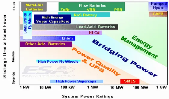
A classification of various technologies in terms of power capabilities and storage capacity is also given in Figure 2.2. Based on these parameters the different storage technologies may fit the requirements of three different classes of applications:
- Power quality - interactions with the grid for periods of the order of sec-onds
- Bridging power - interactions with the grid for periods of the order of minutes
- Energy management - decoupling production and delivery of energy
Figure 2.2 - Accumulation systems and they time of discharge in relationship of the power
An ideal accumulator owns the following main features: - high storage efficiency;
- long operative life;
- high robustness to temperature variations; - negligible self-discharge;
- high capacity/volume ratio; - low cost;
- reduced maintenance
Key features of main available storage technologies are summarized in the fol-lowing.
13
2.1.1 Hydroelectric storage system
The most traditional storage technique is that based on pumping water, from a tank to another placed at a higher level. The water is pumped from the lower tank to the upper tank when the produced energy is larger than the energy demand, and it is later used to produce electricity to face demand peaks. The upper tank may also store energy at zero cost by intercepting meteoric waters [4].
Hydroelectric systems are widespread used all over the world and their technol-ogy is very mature. They are able to quickly control the output power level in order to follow the variations of the load power demand. Furthermore, this technology produces no emissions.
However the density of accumulated power is poor, moreover the realization of new artificial basins an dams is more and more difficult, partially due to the worries of the public opinion after some disasters happened in the last years.
The first pumping systems were made in Italy and Switzerland since 1890 Since 1933 reversible turbines are used both as a motor-pump and as a generator of elec-tricity, currently the obtained technical upgrading allow to get efficiencies up to 85%.
2.1.2 Thermodynamic accumulation
Thermodynamic accumulation is a recently introduced technology mainly used in association with concentration solar thermal systems. These plants operate at high temperature (up to 600°) and are suitable for the generation of electricity and/or heat process for industrial uses. Some parabolic mirrors focus sunlight on a receiver tube, inside which flows a special heat transfer fluid, which absorbs heat and carries it into a storage tank. The tank is connected through an heat exchanger to a generation system using steam turbines.
The heat transfer fluid, a mix of suitable salts, once heated maintains its high temperature (about 550° C) for some days, even not in contact with the heat source. This leads to energy production overnight or with bad weather. Thermody-namic solar plants are relatively simple and inexpensive, but require large spaces.
14
2.1.3 SMES and Flywheels
SMES (magnetic accumulator): The SMES, acronym of Superconducting
Mag-net Energy Storage, is a magMag-netic storage system and consists of a superconducting coil connected to the grid trough a reversible AC-DC converter. The coil is con-nected to a bridge rectifier that allows to conserve energy in the form magnetic.
2
1 2 M
E L I
If necessary, the energy stored in the superconducting coil can be instantly tran s-ferred back to the plant trough the inverter. This technology is still used only for big powers (above 1 MVA) but now it represent a quiet mature technology. One of the advantages of this technology is the possibility to storage large current instantly and release them quickly to meet such a drop in energy or brief blackouts in the utility grid [5], [6].
Flywheels: are electrical machines which can turn electrical energy into
mechani-cal energy (kinetic energy) and vice versa. These systems can accumulate the energy of hundreds of kW for a long time and be recharged quickly. The rotors rotate at very high speeds, from hundreds to thousands of rpm and for this reason often they are referred to as super flywheels. The mechanical energy stored in the mass inertia of the rotor can be converted very quickly into a DC voltage, or a set AC voltages at the desired frequency.
2.1.4 Batteries
Accumulators (or secondary generators) are rechargeable electrochemical d e-vices. After a discharge, during which (as in a battery) the combination of the reagents generates the reaction products and electric power, they are able to perform a recharge, in which, by suitably supplying electric power, reaction products are retransformed in the original reagents, storing energy. These systems may be cycl i-cally charged and discharged a large number of times. Several different batteries exist, among them:
Lead Acid-batteries: The lead-acid cell is the basic element of common
accumulators. It delivers a very high current, is reliable, features a long operative life and works well at low temperatures. The anode is made of dust spongy lead (Pb) and a cathode of lead dioxide (PbO2). In the
mod-15
ern accumulators an alloy of lead, which inhibits the electrolysis of w a-ter, potentially dangerous because producing hydrogen and oxygen gases and risk of explosion, is used. By contrast, lead-acid accumulators are bulky, while the lead is a toxic heavy metal. Moreover, mechanical stress may result in loss of capacity.
Figure 2.3 - Lead acid battery
NiMH batteries: they represent an evolution of nickel-cadmium
batter-ies, featuring a 30-40% higher energy density (Wh/kg or Wh/dm3), and the elimination of the dangerous cadmium. They are light and powerful batteries, but disadvantaged by a noticeable auto- discharge phenomenon.
Lithium batteries: they do not show memory effect and are more
pow-erful than traditional batteries. Unfortunately also the cost is higher. They are largely used in low power portable devices such as cellular phones. The solvent may be flammable
Zinc-Air batteries: belong to the category of fuel cells, where zinc is the
fuel and oxygen is the oxidizing. They feature a lower cost if compared to Lead-Acid accumulators, an high energy density ( from 7 to 10 times that of a Lead-Acid accumulator) and do not contain toxic heavy metals. They also feature a long duration (especially when working at high tem-peratures) and an high safety level (they do not blaze if damaged). On the other hand, they cannot be recharged by the user as the zinc dioxide must be regenerated in special plants. Their performance is also heavily influenced by temperature, humidity and air pollution.
16
Nickel-Zinc batteries: particularly suitable for electric vehicles
applica-tions, due to a light weight and a large output power. They feature an high energetic density, reach 60% of a full charge in 1 hour, do not con-tain toxic materials and do not suffer of memory effect. On the other hand the typical number of charge cycles is low (600-800), and the run-ning in phase is critical for the performance
2.1.5 Fuel-Cells + Electrolyser
A fuel cell differs from an accumulator in that the flow of reagents comes from the outside, such a system is therefore able to supply power without interruption as long as the flow of reagents is maintained. The basic principle of fuel cells is the generation of an electromotive force from combination of reagents (in the simplest case hydrogen and oxygen) through an electrochemical reaction, similarly to electric batteries. It is possible to reach an efficiency higher than 40%, even on small de-vices. Some fuel cells show also co-generation capabilities, further improving the overall energy efficiency.
Fundamentally 6 classes of fuel cells today exist and are classified into two cate-gories: low temperature cells and high temperature cells.
2.1.5.1 Low temperature fuel cell
Polymeric electrolyte cells: they operate at relatively low temperature (60-90°
C), featuring an efficiency as high as 50-60% and high power density (>1kW/kg). These features have made these cells attractive for transport application s road and, to date, are under testing exclusively in this area.
17
Alkaline cells: the electrolyte is composed by an aqueous solution of potassium
hydroxide, operating between 70 ° C and 120 ° C with efficiency great er than 65%. They feature a considerable long lifetime (10000-15000 hours). One disadvantage of these cells is the need to use a fuel (H2) very pure (99.99%) to preserve the integrity
of the electrolyte, the cathode must also be fed by highly pure oxygen (99.99%) . originally developed for space applications, they have few applications in other fields.
Phosphoric acid cells : the electrolyte consists of a concentrated solution of
phosphoric acid operating at around 200 ° C. They are suitable for cogeneration with efficiency of about 60%. They feature a considerable long lifetime (10000 -15000 hours). Today the more mature technology, but expensive.
Direct methanol cells: use methanol directly into the anode. The electrolyte is
composed of a polymer membrane as PEM cells. Their operating temperature is between 70 ° C and 100 ° C. Currently, the efficiency is around 35%, while the power density is about 180-250 mW /cm2. They are suitable for low power applica-tions, represent a viable alternative to the traditional batteries in electronic portable devices.
2.1.5.2 High temperature fuel cell
Solid oxide fuel cell: they work at high temperature (900 ° C - 1000 ° C), the
electrolyte are realized with ceramics materials. They are more durable and robust than cells with liquid electrolyte. The fuel (natural gas, biogas or coal gas) can be fed directly to the anode without being "reformed". The gas flow at high temperature made available to the discharge of the cell, allows the construction of installations combined with gas turbines and obtain efficiencies over 70% (Siemens Westing-house). They are very promising for static generation, although burdened by high operative temperatures.
Fused carbonates cells: cells working at high temperature (650 ° C) using a
so-lution of alkaline carbonate (at operating temperature of the cell) as electrolyte. Reaction kinetics are much faster than the cells at low temperatures and do not require the use of precious metals as catalysts. Have the ability to directly power the cell with natural gas or light fuel without the stage of reform of the external fuel also have the opportunity to combine a microturbine. The efficiencies are of the order of
18
60-70%. Able to produce temperatures of industrial interest and therefore suitable for co-generation.
2.1.5.3 Electrolyzer
An electrolyser is substantially an electrolytic cell that, respect to a fuel -cell, per-forms the inverse operation. In this system, in fact, a chemical reaction causes the electrolytic transformation of electricity into chemical energy, producing hydrogen and oxygen. Modern alkaline electrolysers operate at 120 ° and pressures up to 30 bar. This drastically reduce the size, while increasing the rate of production of hydrogen and also improving the efficiency. Alkaline electrolysers are mai nly used to produce hydrogen on an industrial scale even they are also available in small sizes. The main drawback of these systems is a cost too high to permit a large diffusion.
The fuel cell + electrolyser system may be seen as a high-efficiency accumulation device. The electrolyser allows in fact to accumulate energy under the form of hydrogen when an excess of power takes place, while the fuel cell allows the re -transform the stored hydrogen into electric power when a deficit of available power is detected. By also storing the oxygen produced by electrolysis it is also possible to increase the efficiency of the fuel-cell feeding it with oxygen rather than with air. Such a possibility has however to be accurately evaluated due to the cost and co m-plexity of the oxygen storage system.
The fuel cell + electrolyser system allows to decouple the production of energy from renewable sources by the availability of the primary power, with the additional possibility of integration with low or zero emission mobility systems. The high energy storage density suggests the use of such systems in applications requiring high accumulation capacity but a relatively low power.
Hydrogen storage is today possible according to different physical or chemical principles. In particular the following technologies are available:
High-pressure (200-250 bar) tank at ambient temperature: the storage of the
hydrogen at ambient temperature and low pressures is quite unpractical, because of the excessive volume of the tanks. Therefore, in order to save space it is necessary to increase the pressure up to 200 bar or more.
Cryogenic accumulators: the storage of the hydrogen in liquid form allows to
a-19
tures that only can be reached through a procedure of mechanical compression and cooling requiring a noticeable amount of energy.
Accumulators with absorbent materials: hydrogen in form of molecules in the
gaseous state may be captured into absorbent materials such active coal or carbon nanostructures. However, it is necessary to cool the absorbent material up to -200°C to reach specific stored energy levels of practical interest.
Accumulators with metallic hydrides: hydrogen may be chemically combined
with different metals and metallic alloys, forming hydrides. In this form the hydro-gen can be trapped at relatively low pressures. Major problems of metallic hydrides accumulators are the weight and the low store capability.
2.1.6 Regenerative fuel-cells
Regenerative fuel-cells can be used to produce hydrogen from electricity and to generate electric power from hydrogen and air as well. They therefore act as systems composed by separated fuel cells and electrolysers, but are formed by a single element. Regenerative fuel-cells are today under development and have not yet reached a degree of sufficient maturity. Power losses are higher in the fuel -cell mode of operation and a total efficiency (round-trip) of 40-46% is reached with a 500mA/cm2 current density. This is satisfactory if compared with the typical per-formance of separate fuel-cell and electrolyser system, although the cost is much higher.
2.1.7 Flow batteries
Flow batteries are a special class of batteries where a large amount of electrolyte is stored in external tanks and driven through a the galvanic cell by pumps or ex-ploiting the force of gravity. Such batteries are charged as normal batteries, but the energy, rather than be stored by the electrodes, is supplied to the electrolyte [7].
Flow batteries may have an extremely high capacity and are used in large systems as accumulators for naval applications, or storage stations. They feature an high efficiency, long life time, easy scalability and negligible environmental, while are burdened by a low energy density if compared with other accumulation devices.
20
Zinc-Bromine and Vanadium redox batteries are examples of flow batteries commercially available. The last, also said VRB-ESS, use the oxidation – reduction of the vanadium, to convert chemical energy into electric power and vice versa. A VRB-ESS system is made of two electrolyte tanks, respectively containing van a-dium in two different states of oxidation (positive: V(IV)/V(V) redox couple, negative: V(II)/V(III ) redox couple) and a stack of PEM cells.
Figure 2.5 - VRB Energy storage system scheme
The two fluids are put in circulation by two pumps, in order to cross the stack of PEM cells. When the charged electrolyte crosses the stack, the electrons transferred by the different ionic forms of the vanadium across the membrane are forced to flow in an external electric circuit. Vice versa, by forcing a current in the stack through an external power source, the inverse process take place and the recharged electr o-lyte is pumped back in the tanks. A VRB -ESS system can be cyclically charged and discharged more of 10.000 times, moreover, thanks to the relatively fast kinetics of the redox couple high efficiencies can be obtained, without the use of expensive catalysts.
21
VRB -ESS systems can be easily expanded. In fact it is possible to increase the storage capacity simply increasing the size of the electrolyte tanks, while it is possible to increase the rated power by adding new cells to the stack.
These systems work at low temperatures and ensure a power availability higher than 98%.
2.1.8 Supercapacitors
Are devices designed to provide an high power for short time periods (few mi n-utes), and to be recharged very quickly. They can be used to balance load peaks, or to complement conventional batteries in high dynamic storage systems [8].
Supercapacitors are not suitable to supply power for long times because of an energy density much lower than that of conventional batteries. On the other hand, supercapacitors feature an expected lifetime much longer than conventional batteri es and a higher efficiency.
22
23
2.2 Renewable energy sources – Overview
A form of energy is considered renewable if its source is regenerative or not "e x-hausted" in the human time scale and whose use does not affect natural resources for future generations. Generally are considered "renewable energy" the sun, the wind, the sea, the geothermal while a "non-renewable” resource is a natural resource which cannot be produced, grown, generated, or used on a scale which can sustain its consumption rate. Fossil fuels (such as coal, petroleum and natural gas) and nuclear power (uranium) are examples. These resources often exist in a fixed amount, or are consumed much faster than nature can create them.
In this context there is often a distinction between renewable "classic" (mainly hydroelectric and geothermal energy) and "new" renewable sources, such as solar, wind and biomass. In the context of electricity, renewable sources are also classified into "programmable sources" and "non-programmable sources", as they can be scheduled on demand for energy or not. According to the definition of the Gestore dei Servizi Elettrici (GSE) the first group includes hydroelectric plant with reservoir and basin, solid waste, biomass, plant treated using fossil fuels, fuel or process residues, while the second group (non-programmable) are flowing hydroelectric plants, wind, geothermal, solar, biogas.
2.2.1 Geothermal energy
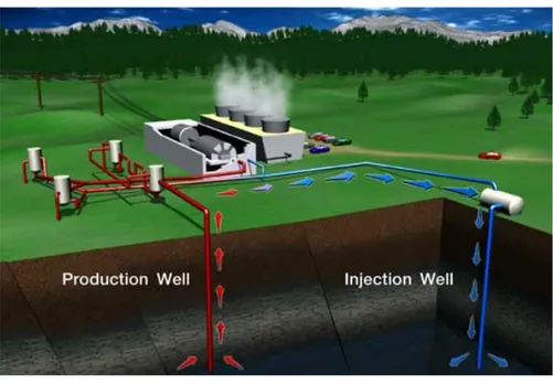
Geothermal energy is produced using the heat, partly originated during the form a-tion of the planet and in part produced by the decay of radioactive isotopes present in rocks of deepest parts of the globe. This heat is constantly transferred from the earth to the surface through convection of magma or water; because of this heat flux, the temperature of rocks increases by about 30 ° C per km(geothermal gradient). Rainwater, deeply infiltrating, flows underground through porous rock and becomes warmer, sometimes up to high temperatures, and sometimes till becoming steam. The geothermal fluid (water or steam) is transferred to the surface through a m e-chanical perforation (geothermal wells), so after some treatments, is sent to user plants (production of electricity in geothermal power plants or direct use).
Geothermal energy has several advantages:
24
do not produce pollutants or increase emissions of carbon dioxide or other gases in the area affected by geothermal manifestations;
no risk of fire or gaseous emissions as there are no fuel of any kind (gas, oil or derivatives);
provides heating, cooling and hot water every day for 24 hours;
no maintenance required;
no noise.
Figure 2.7 –Geothermal energy plant scheme.
However, this form of energy also has some negative aspects:
a geothermal plant is more expensive than a conventional and recovery times are extremely long in contrast to the considerable reduction in operating costs;
it has some adverse effects on the environment pollution due to geothermal fluids and seismic problems (areas with geothermal sources are often seis-mic) and there is a subsidence and seismic effects induced by the exploitation of the fields;
25
2.2.2 Hydroelectric Energy
Hydroelectric power is derived from the course of rivers and lakes through the creation of dams and pipelines. The water of a lake or reservoir is transported through pipelines downstream, transforming its potential energy into kinetic energy through the distributor and the turbine. A hydroelectric power plant is a complex machinery that conveys volumes of water from a higher to a lower altitude, to exploit the potential hydraulic energy, usually a river, that is converted into electri c-al energy.
2.8 - Hydroelectric power plant scheme
A hydropower plant consists of a water collection system at the highest altitude, water transport facilities (pipelines), equipment that transform hydraulic energy into mechanical energy (turbines) and then in electrical (alternator + transformer).
Hydropower is a clean and renewable source of energy, produces no harmful emissions (pollutants, dust or heat) or noise. However, the construction of dams and large reservoirs, with the flooding of vast land, may cause disruption of the ecosystem with enormous environmental damage.
26
2.2.3 Energy from the sea
Sea is a potential source of renewable energy. Different solutions fo r the exploi-tation of several natural phenomena occurring in the sea are being studied and / or are under testing. It is possible to convert into electricity at least three types of energy in the sea:
tidal current energy;
wave energy;
salt gradient energy;
2.2.3.1 Tidal current energy
Among different renewable energy source, the tidal current energy is one of the most interesting and unexplored sources. In Europe, for example, the availability of this energy is approximately 75 GigaWatt. The turbines for the expl oitation of marine currents may be (as for wind technologies) with horizontal or vertical axis. Even the technology of marine current generators is far to be mature and some major technical problems must be still solved, a promising solution has been recently proposed, based on the Kobold turbine concept.
2.2.3.2 Salt gradient energy
Saline gradient energy also known as osmotic energy is energy obtained from the difference in salt concentration between seawater and freshwater (eg the mouth of a river). It is possible to obtain energy from salinity gradient using two different methods: the electro reverse dialysis, also said osmosis, and Pressure Retarded Osmosis (PRO). Both are based on osmosis obtained by membranes for specific ions. Many laboratory tests have confirmed the effectiveness of osmosis for the production of energy. In the past years the cost of the membrane could become an obstacle to the development of this technology, today a new cheaper electrically modified polyethylene membrane is available ideal for a potential commercial use.
2.2.3.3 Wave energy
There are various techniques to exploit the wave movement. A known example is the Pelamis turbines (tested in Portugal), consisting of tubular structures floating while anchored to the seabed. Within the structures, the turbines are moved by water moving in and out from the structures to the rhythm of the waves where the
27
generator is located. These generators produce energy constantly, take up a large amount of space.
Main advantages are low environmental impact (offshore plants), high availabil-ity of the primary resource and high degree of predictabilavailabil-ity. On the other hand technologies are not mature and the costs are still to high.
2.2.4 Biomass energy
The term biomass means any vegetable or animal organic form from which it is possible to obtain energy through thermochemical or biochemical processes. Biomass are made from waste biomass production activities. Instead, energy crops require the selection of species most suitable for energy production in order to maximize energy efficiency and minimize the production cycle. Biomass is the most sophisticated form of solar energy storage.
Figure 2.9 - Biomass cycle
Through the process of photosynthesis, plants absorb carbon dioxide and co n-vert it into glucose, each mole of glucose has an energy content of 2872 kJ. It is considered a renewable and inexhaustible resource, if used properly, or if the usage rate does not exceed its regenerative capacity. Biomass can be used directly as fuel or converted into other substances (solid, liquid or gas) that are easier to use in conversion plants.
Biomass Energy doesn’t cause the increase of CO2 in the atmosphere, because the amount of gas released during their combustion is the same as that absorbed during
28
growth through photosynthesis. Stating that the biomass is renewable with no environmental impact is a big stretch, but it is certain that emissions are below the values recorded in the case of traditional fossil energy sources.
However, these fuels have economic and technological problems due to their specific properties.
2.2.5 Solar energy
Solar energy means energy, thermal or electric, produced directly using the radiant energy emitted from the Sun to the Earth. Thermonuclear fusion reactions that occur inside the sun release enormous amounts of energy in the form of electromagnetic radiation. Part of this energy, after passing through the atmos-phere, comes to the ground with an intensity of about 1.000W/m2 (radiation on a clear day at noon.) The average solar radiation, the European latitudes, about 200 watts per square meter. However, only a portion of this energy can be used, since it is necessary to collect it from large areas in order to have a significant amount. Solar energy can be used to generate electricity (solar photovoltaics) or heat (solar thermal and thermodynamic).
2.2.5.1 Solar thermal
Solar thermal technologies include all those in which solar radiation is used to heat thermal energy derived from solar radiation can be "captured" in many ways and used for the various energy needs: as heat for the production hot water for sanitary and heating, but also for cooling energy, electrical or mechanical. Current technologies also allow combined several types of energy.
A solar heating system consists of the following elements: a sola r collector (known as "solar panel") which captures the sunlight and converts it into heat; The tank that stores the heat generated to make it available when needed; collectors are crossed by a fluid that is able to carry the heat received from the sun to thermal transfer and storage systems; the security components (pump, expansion tank, safety valves, etc..) manage the operation of the entire system.
The most important benefit is the reduction of pollution. Compared to a traditional system, in fact, the use of solar collectors enables reduction of air emissions to 70%. In addition, no toxic, flammable or otherwise dangerous
29
elements are used: the whole system is not a source of risk or noise . Solar thermal collectors have a number of problems. First of all, their inability to function in the absence of sun so it is essential to integrative solutions.
2.2.5.2 Solar Thermodynamic energy
The Solar Thermodynamic or concentrating solar power is a technology using solar energy to generate electricity for practical applications. It can provide heat to medium and high temperature (up to 600°), allowing use in applications for elec-tricity generation and / or process heat for industrial uses. This technology is used exclusively for industrial plants, that produce high-temperature heat and thus need to concentrate large amounts of sunlight onto a small area. The advantage found in the immediate time than the typical PV system consists of a continuous production of energy, even at night or during bad weather, thanks to a salt -based fluid that, when heated, retains its high temperature (about 550 ° C) for several days without being in contact with its source. Most of current commercial systems use parabo l-ic trough collectors and a synthetl-ic oil as heating fluid, whl-ich allows op erating temperatures up to 400 ° C, limiting the thermodynamic efficiency.
2.2.5.3 Photovoltaic energy
Photovoltaic technology is able to transform directly and instantly, the energy associated with solar radiation into electrical energy. It uses the photovoltaic effect, based on the properties of some semiconductor materials which, if properly processed and interfaced, are able to generate electricity when hit by sunlight. The basic component of the photovoltaic array is the cell, consisting of a thin slice of a semiconducting material, usually silicon properly treated, of thickness of 0.3 mm about. The main technologies currently used in the panels are based on silicon (60% using the monocrystalline silicon, polycrystalline silicon 25% and 11% amorphous silicon).
To reduce the cost of cells, new technologies are currently object of study using amorphous silicon and thin-film cells, in addition to other polycrystalline materials such as copper indium selenide of cadmium and tellurium. Everything indicates that these thin-film cells will fill most of the early disadvantage in terms of Wp/m2, making it more economical. Modularity of photovoltaic panels allows a wide flexibility of use: the cells can be connected in series or in parallel to obtain
30
the desired voltage (for cells connected in series the voltages are additive, cells connected in parallel to the currents are additive).
Photovoltaic technology offers special advantages. It can be used anywhere and can be produced wherever it is needed and in quantities close to the actual demand, thus avoiding losses due to transportation. There is a wide range of applications, from a few milliwatts for the pocket calculator, till a dozen of megawatts for power and the power plant can be modified at any time without problems. Besides it produces no pollution of any kind.
A photovoltaic system has a considerable initial cost, which varies by location and consumers' needs. It is heavily influenced by weather conditions.
2.2.6 Wind energy
Wind power is the product of the conversion of kinetic energy of wind into other forms of energy. First of renewable energy for its cost -production, it has been also the first renewable energy source used by man.
A wind turbine consists of several parts: • rotor • braking System • gearbox • power generator • transformer • steel tower.
There are wind turbines of different shapes and sizes, and therefore power. They may have one, two or three blades of different length
Wind energy has the following advantages:
• is an inexhaustible and free, available in many areas of the earth; • requires a rather simple and mature technology;
• allows a consistent performance over time; • has a low cost of the generator;
• does not produce emissions.
Main problem of wind energy is its inconsistency, eg. 10,000 3 MW wi nd turbines can produce power very different: on a summer day of "Dead Calm", could pr
o-31
duce only 1,000 MW, but in an autumn day, with winds strong and steady, can exceed 20,000 MW.
32
Chapter 3
Design criteria for energy storage devices
for distributed generations system
3.1 Introduction
The availability of primary power of a renewable energy source, such as wind or solar energy, depends on weather and environmental conditions such as wind speed or insolation level on the ground. To ensure the minimum level of power continuity required to supply a generic network of electrical loads these systems must be integrated with energy storage devices. In particular, generation systems operating in island mode must be integrated with an energy storage system to compensate the differences between the availability of primary power and the power required by the load during the intervals of insufficient generation. Ther e-fore, for distributed generation systems, sizing of the entire system has an important role [9].
Sizing is a multivariable and quite complex problem, due to non-linear characte-ristics of components.
In literature are proposed different criteria for sizing systems operating in the island mode but they do not seem to afford a fully comprehensive solution.
This chapter describes the two most common criteria for sizing energy storage systems underlining the advantages and limitations.
33
3.2 Analysis of technical literature – Overview
A first aspect that must be addressed is the unpredictability and discontinuity of the availability power of renewable energy sources.
Determination of environmental variables such as wind speed and the level of solar irradiation, which are directly related to the power generated, is a preliminary stage in sizing. For evaluation of these data different mathematical tools are adopted based of theoretical and empirical model. Available models, however, are complex and can predict the dynamics of quantities of interest only to narrow times.
An assessment of available power versus time for sufficiently lon g intervals, however, is necessary for the definition of each size criteria. In literature there are different assessment approaches but they are based, however, on processing of data previously collected from meteorological observation stations.
A first approach is to consider average values of diagrams of insolation and wind speed. For example, some authors assume the generating function an average daily profile calculated on a yearly basis or monthly average values.
Methodology neglects the occasional and transient phenomena that occur over short intervals of time and forces, then, to take strong factors of excessive size and / or provide auxiliary generation systems. Another possible approach is to use directly time series data collected by distributed weather stations.
The starting point is the assumption that the environmental conditions are cyc-lic. A solution is to analyze the statistical properties of time series to highlight behaviors recurring over time for different locations. The task is to determine the probability distributions of wind speed, solar irradiation or variables related to them for the whole year. The analysis shows in this direction confirm for the wind speed probability distribution as the typical Weibull distribution and Weibull (or Beta) type distributions for levels of solar irradiation.
Analysis of probability distributions is a quite common starting point of conven-tional design procedures. Probabilistic methods offer greater reliability than those using average data, but are characterized by significant computational costs and need archives of meteorological data of previous years.
Use of random variables can be particularly advantageous, because statistical properties can be considered valid for locations where meteorological observations
34
were not made in the past. Other methodologies, more sophisticated but less common in the literature, are based on the consideration that the dynamics of certain environmental variables could be regarded as stochastic processes. This means that the wind speed, for example, is considered as a random variable. More suitable mathematical tools for such modeling are the “Markov chains” used to assess the probability that a variable may assume a specific value, on the basis of the analysis of a suitable set of previously assumed values. Analysis of daily availability of renewable energy sources is the starting point to size the system components. The selection of such devices must be related to a given objective function, which maximizes system performance (costs, weight, dimensions). In technical literature there are no explicitly defined criteria that connect characteri s-tics of the generation system to the storage system, and generally approximate methods or numerical simulations are used.
A common method used in practical applications separately sets the size of the generating system and that of the storage system. The generation system is de-signed so that the monthly average power, calculated in the worst month, is equal to the average power absorbed by the load. The energetic capacity of the storage system is, however, scaled on the basis of a minimum period of autonomy ( N.A.D. Number of Autonomous Days) that the integrated system should ensure at full load with just the energy stored, ignoring the contribution of the generated energy. Usually, the period of autonomy ranges from three to ten days, depending on the expected performance in terms of continuity of power supply required.
The N.A.D. technique features a remarkable simplicity of the entire sizing pro-cedure and a good level of reliability proven by years of operation of such realized systems. For these reasons, this design criterion is also suggested by the IEEE standards and is adopted on a regular basis by some telephone companies for the installation of radio base stations (Telecom Australia). The drawbacks of this technique criterion are substantially related to an excessive over-sizing of the storage system that has an impact on costs of plant.
Recently a new technique was developed based on probabilistic considerations on plant availability. The basic idea is to define an index (L.O.L.P., Lost of Load Probability) expressing the probability that at given time the system does not allow properly supply to the load.
35
Pr U( ) L
LOLP P t P t (3.1)
where PU (t) is the maximum power that the combined system of generation and
storage can provide and PL (t) is the load power demand. The L.O.L.P. index also
coincides with the ratio between the number of hours of power failure and hours of normal operation of a system.
For a given value of the L.O.L.P. index different system configuration are con-sidered. For a given L.O.L.P. value the most convenient configuration is then detected by minimization of a suitable function (typically the cost).
The choice of the optimal value of the index depends on the desired syste m re-liability and can be determined by a preliminary risk analysis (risk analysis). Most of the implementations prefer a numerical determination through intensive use of the Monte Carlo method. Using time series and probability distributions of wind speed and solar irradiation different configurations of system are simulated. For each configuration a value of the index is determinate. Different model could be adopted for the simulation of each part of the system. These are quiet complex and can reproduce the behavior of the entire system. Since the same index value may correspond to multiple configurations, a procedure detects the minimum cost configuration. Numerical analysis shows a close correlation between the size of the storage system and the size of the generation system. Such an analysis, however, does not allow to obtain explicit correlations to understand how the various quanti-ties depend on system variables. The L.O.L.P. method reduces the oversizing of power generators from renewable sources as confirmed by positive experiences on prototypes.
There are several versions of the method sharing the basic idea, but are based on the definition and calculation of slightly different indexes (for example related to relationships between energy and not time). The extensive literature produced in recent years shows that the LOLP method is currently the most accredited. Draw-back of LOLP are substantially related to the considerable amount of calculations involving the simulation of different system configurations under consideration. Another limitation of the method is that it gives results only impl icitly and any directives of the project can only be extrapolated by calculation examples.
Another interesting alternative to traditional approach is a probabilisti c index used to evaluate the availability of a system exploiting a renewable energy source
36
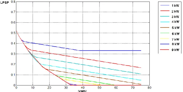
to supply a load. This index is the L.P.S.P( Lost of Power Supply Probability) and it expresses the probability that in a interval of time (day, month, year) there i s a lack of power load.
3.3 Loss of Power Supply Probability (L.P.S.P.)
The probabilistic index LPSP (Loss of Power Supply Probability) is an estimate, on a time interval, of a lack of load power supply occurring in a generation system operating in island mode. By definition the index is directly an assessment of the reliability of the system that takes into account the load demand profiles, the availability of primary energy source and, if present, the capacity and performance of charging and discharging of the storage system. The resulting evaluations lead to good results for the determination of the size of the storage system that ensures an acceptable continuity of load power supply. Typically values of this index below or equal to 0.0003, which corresponds to about one day of lack of load power in ten years, are considered sufficient.
A given period of time T is divided into N intervals and for each of these the amount of energy produced by one or more renewable sources is calculated. The energy produced is then compared with that required by the load in the same interval. If the difference of these two quantities is positive, then Eg(k)>Eload(k),
the surplus is used to charge the storage system taking into account the charging efficiency (it should be noted that this occurs only if the battery charge is not at its maximum value), viceversa, when Eload(k)>Eg(k), energy is delivered by
accumula-tion device. In this case, if the total energy available is not sufficient to provide power to the load, the Lost Power Supply of the i-th interval is evaluated as follows:
Load g ESS ESS SPC
LPS(k) = E k - E k + E k-1 Cmin (3.2)
Where Eload (k) is the energy required by the load, Eg(k) is the energy produced
from renewable source, Eess(k) is the energy in the form of state of charge in the
accumulator, multiplied by the efficiency of discharge ESS, is the efficiency of the conversion system, and Cmin and Cmax are the minimum and the maximum
value of the state of charge allowed.
37
Figure 3.1 – Flow-chart of LPS
The total value of the index is then calculated as reported in the following equ a-tion:
(3.3) The LPSP index is suitable to a wide range of analysis allowing evaluation in terms of energy and economy. Appropriate changes are then made on the basis of the considered problem.
In its original definition the index does not takes into account the rated power of the storage system but only the energetic capacity. For this reason, when poss ible solutions using flow batteries or fuel cells are analyzed, it is necessary to introduce another degree of freedom related to the system rated power. This limits the amount of energy that can be stored in a given interval when the energy produced is greater than the load requirement and the amount of energy released when there is an energy demand by the load. For this reason the index has been modified to