UNIVERSITY
OF TRENTO
DIPARTIMENTO DI INGEGNERIA E SCIENZA DELL’INFORMAZIONE
38123 Povo – Trento (Italy), Via Sommarive 14
http://www.disi.unitn.it
INNOVATIVE DESIGN OF A PLANAR FRACTAL-SHAPED
GPS / GSM / WI-FI ANTENNA
R. Azaro, E. Zeni, P. Rocca, and A. Massa
March 2008
Innovative Design of a Planar Fractal-Shaped
GPS / GSM / Wi-Fi Antenna
R. Azaro, E. Zeni, P. Rocca, and A. Massa
Department of Information and Communication Technology University of Trento, Via Sommarive 14, 38050 Trento, ITALY
E-mail: [email protected]
Abstract – In this letter, the design of a microstrip three-band antenna working
in GPS, GSM and Wi-Fi frequency bands is described. By considering a planar geometry printed on a dielectric substrate, the tuning of the antenna behavior in three non-harmonic frequency bands is obtained perturbing the patch perimeter according to a Koch-like fractal shape. The synthesis procedure is automatically performed by means of an iterative PSO-based optimization strategy where a fractal boundary generator is integrated with a MoM-based electromagnetic simulator. The feasibility of the approach as well as the reliability of the synthesized antenna is assessed through simulations as well as experimental results.
Introduction
The design of multi-band antennas has attracted the attention of several researchers due to the growing demand of radiating devices able to provide multiple reception and transmission functionalities in a limited volume. Such a task has proven to be trivial at all, since project guidelines usually require uncorrelated resonance frequencies instead of the harmonic behavior of classical antenna structures [1]-[3]. Concerning conventional techniques, the insertion of reactive loads in the radiating structure has been considered to
obtain a non-harmonic radiating behavior. Such a solution has been employed in dealing with wire antennas and, recently, it has been also proposed using fractal geometries. As a matter of fact, fractals have been extensively studied because of their interesting electro-dynamical properties [4][5][6] that allow both miniaturization and multi-band behavior. Although standard pre-fractal shapes present harmonic relationships among resonance frequencies [7], suitable deformations of their building geometrical elements cause an increase of the degrees of freedom in the antenna frequency response. Accordingly, some interesting results have been obtained by assuming as reference geometry that of a standard monopole-like fractal (e.g., the Koch curve). Notwithstanding, the overall dimensions in the direction orthogonal to the reference ground plane usually prevent their use in applications where conformal shapes are required (e.g., automotive or aeronautical frameworks). For these applications, the adoption of conformal patches is an optimal choice, but a cavity-like resonance frequency behavior occur [10][11]. In order to fit both geometrical and electrical constraints, the exploitation of fractals in designing patch antennas has been studied [5].
In such a framework, this letter describes the synthesis of a patch antenna, which operates in three non-harmonic frequency bands, carried out by perturbing the boundaries of a reference rectangular patch according to a fractal-based erosion process. Numerical and experimental results are shown for assessing the effectiveness and reliability of the synthesized prototype.
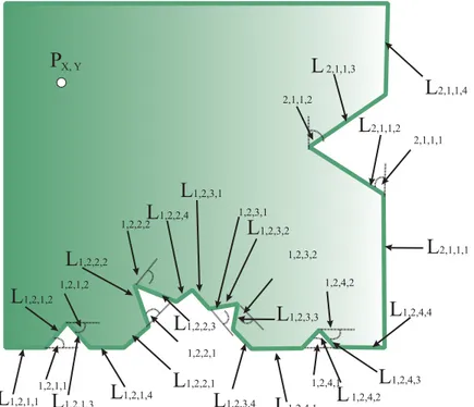
Starting from a rectangular patch, the perimeter of the antenna has been modified by determining the lengths of fractal segments in order to tune three resonant modes of the reference structure for satisfying the project constraints. A sketch of the antenna geometry, where the optimization parameters to be tuned are indicated, is shown in Fig. 1.
As far as the project guidelines are concerned, the following constraints have been taken into account: a) working bands: L1 GPS, GSM, and Wi-Fi centered at f1=1575.42MHz, f2=1850.00MHz, and f3 =2440.00MHz,
respectively; b) Voltage Standing Wave Ratio (VSWR) values smaller than 2 at the resonance frequencies; c) hemispherical coverage with a main lobe
width θ−9dB =70°; d) maximum dimensions of
[ ]
2
10
10× cm ; e) Arlon substrate
(thickness h =0.8
[ ]
mm , εr =3.38, tgδ =0.0025 at f =10GHz).Because of the dimensionality (i.e., the number and range of values of the unknowns) of the problem at hand, the array of the unknowns
[
xinput;yinput;L1,2,m,i;Θ1,2,n,j;L2,1,1,p;Θ2,1,1,q]
=
χ (1)
where m,i,n,p=1,...,4 and j,q =1,2;
(
xinput,yinput)
being the location of the feedpoint, has been determined exploiting an iterative stochastic optimization strategy. In order to quantify the fitting of a trial solution to the project constraints, a suitable cost function has been defined. It was a two-term function
( ) ( ) ( )
χ =Ωχ +ΓχF (2)
( )
∑
−( )
= Φ ∆ − = Ω 1 0 max max , 0 max T t VSWR VSWR f t χ (3)as well as radiations properties
( )
∑ ∑ ∑
−(
) (
)
= − = − = ∆ ∆ ∆ −Λ ∆ ∆ ∆ = Γ 1 0 1 0 1 0 min min , , , , , 0 max U u V v Z z G f z v u f z v u G θ ϕ θ ϕ χ (4)( )
fΦ and Λ
(
θ,ϕf,)
being the value of the VSWR and the value of the gainfunction computed in correspondence with the solution χ , respectively.
Moreover, f∆ is the sampling frequency step in the resonance bands, and
θ
∆ and ∆ϕ are the angular steps when computing the gain function.
Concerning the iterative minimization of (2), a PSO strategy [12] has been used since it proved to be very effective and versatile in several antenna synthesis problems [8][9][13]. Towards this purpose, the fractal Kock-like
boundary generator ℑ has been integrated with a MoM-based [14]
electromagnetic simulator for computing the VSWR values [Φ
( )
f =VSWR{ }
ℑ(χ) ] and the gain function [Λ(
θ,ϕ,f)
=G{ }
ℑ(χ) ] in correspondence with every trial solution generated during the evolution of the optimization.The iterative loop has been implemented as follow:
a. Generation of a set of trial solutions χ(nm), m=1,...,M being the trial solution index and n=1,...,N being the iteration index;
b. Use of the pre-fractal generator for building the antenna shape (n) m
α
corresponding to the trial array χ(nm), ( )
{ }
(n) m nm χ
α =ℑ ;
c. Computation of the values of electric parameters of each trial antenna
through the MoM electromagnetic simulator [ ( )
( )
{ }
(n)m n
m f =VSWRα
(
)
{ }
( ) ) ( , , n m n m θϕf =GαΛ ] and evaluation of the corresponding cost function
value ( )
{ }
(n) m nm F
F = χ ;
d. Updating of the set of M trial solutions by means of the PSO strategy [12][13],
{
χ(mn+1);m=1,...,M}
=PSO{
χ(mn);m=1,...,M}
;e. Iterative repetition of steps (b.)-(d.) until a fixed heuristically-defined maximum number of iterations n = is reached. N
Numerical Results and Experimental Validation
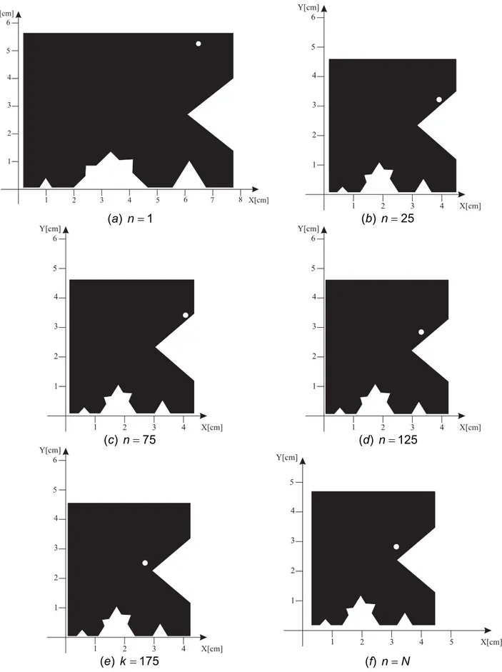
The process synthesis has been carried out by considering the following setup: N =250 and M =10. For illustrative purposes, Figure 2 shows the evolution of the trial shape as well as of the position of the feed point (white dot) up to the optimized one [Fig. 2(f)] whose patch support has a maximum dimension of 41.1×45.5
[ ]
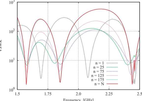
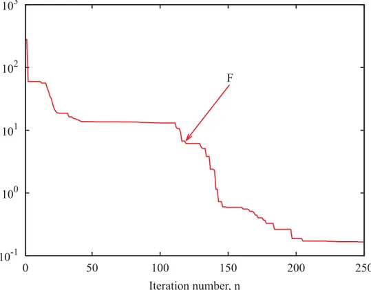
mm2 . For completeness, the plots of the VSWR values are reported in Figure 3. As it can be noticed and confirmed by the plot of the cost function F( )
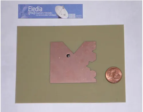
χ versus the iteration number (Fig. 4), the electric behavior of the trial solution evolves from an unsatisfactory compliance with the project constraints until an accurate fitting.In order to complete the assessment with an experimental analysis, a prototype of the fractal-shaped patch antenna (Fig. 5) has been built by using a photolithographic printing circuit technology. Then, it has been equipped
with an additional ground plane of dimensions 90×140
[ ]
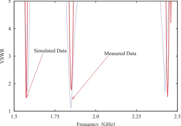
cm2 forapproximating the numerical modeling of the simulated structure (i.e., the patch over an infinite ground plane). For comparison purposes, simulated and measured (in an anechoic chamber) VSWR values are reported in Fig. 6. As
its can be observed, there is a good agreement that further points out the reliability of the numerical synthesis procedure.
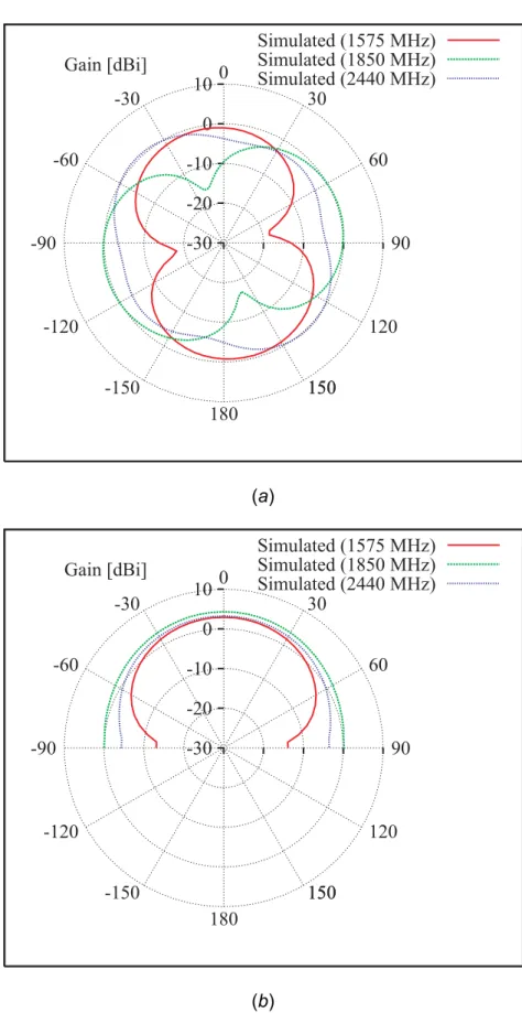
Finally, for completeness, the radiation properties of the synthesized antenna are analyzed. In particular, the plots of the horizontal and vertical (φ= 0°) gain patterns are shown in Fig. 7. As expected, the obtained results turn out compliant with the project specifications since an hemispherical coverage, suitable for both GPS and mobile communication systems, is obtained whatever the frequency band.
Conclusions
In this letter, the design of a three-band fractal-shaped patch antenna has been described. Starting from a set of design constraints, the perimeter of the rectangular reference structure has been iteratively modified by optimizing the descriptors of the fractal boundaries and the position of the input port through a PSO-based procedure. The synthesized structure has been analyzed both numerically and experimentally by considering an antenna prototype.
Acknowledgments
This work has been partially supported in Italy by the “Progettazione di un Livello Fisico ‘Intelligente’ per Reti Mobili ad Elevata Riconfigurabilità,” Progetto di Ricerca di Interesse Nazionale – MIUR Project COFIN 2005099984.
References:
1 W. L. Stutzman and G. A. Thiele, Antenna Theory and Design. Wiley,
New York, 1981.
2 J. D. Kraus, Antennas. McGraw-Hill, New York, 1988.
3 C. A. Balanis, Antenna Theory: Analysis and Design. Wiley, New York,
1996.
4 D. H. Werner and R. Mittra, Frontiers in Electromagnetics. IEEE Press, Piscataway, 2000.
5 J. Gianvittorio and Y. Rahmat-Samii, "Fractals antennas: a novel antenna miniaturization technique, and applications", IEEE Antennas
Propagat. Mag., vol. 44, pp. 20–36, 2002.
6 D. H. Werner and S. Ganguly, "An overview of fractal antenna engineering research," IEEE Antennas Propagat. Mag., vol. 45, pp. 38-57, 2003.
7 C. P. Baliarda, J. Romeu, and A. Cardama, "The Koch monopole: a
small fractal antenna," IEEE Antennas Propagat. Mag., vol. 48, pp. 1773-1781, Nov. 2000.
8. R. Azaro, G. Boato, M. Donelli, A. Massa, and E. Zeni, "Design of a prefractal monopolar antenna for 3.4 – 3.6 GHz Wi-Max band portable devices," IEEE Antennas Wireless Propagat. Lett., vol. 5, pp. 116-119, 2006.
9. R. Azaro, F. De Natale, M. Donelli, E. Zeni, and A. Massa "Synthesis of a prefractal dual-band monopolar antenna for GPS applications," IEEE
Antennas Wireless Propagat. Lett., vol. 5, pp. 361-364, 2006.
10 R. Garg, P. Barthia, I. Bahl, and A. Ittipiboon, Microstrip Antenna Design
Handbook. Artech House, Norwood, MA, 2001.
11 D. M. Pozar and D. H. Schaubert, Microstrip Antennas: the Analysis and
Design of Microstrip Antennas and Arrays. IEEE Press, New York, 1995.
12 J. Robinson and Y. Rahmat-Samii, "Particle swarm optimization in electromagnetics", IEEE Trans. Antennas Propagat., vol. 52, pp. 397– 407, 2004.
13 R. Azaro, F. De Natale, M. Donelli, A. Massa, and E. Zeni, "Optimized
design of a multi-function/multi-band antenna for automotive rescue
systems," IEEE Trans. Antennas Propagat. - Special Issue on
“Multifunction Antennas and Antenna Systems,” vol. 54, no. 2, pp. 392-400, 2006.
14 R. F. Harrington. Field Computation by Moment Methods. Robert E.
Figure captions:
Fig. 1. Sample of a trial fractal-shaped patch antenna.
Fig. 2. Evolution of the trial geometry during the optimization process.
Fig. 3. Plots of the VSWR values at different iterations of the optimization process.
Fig. 4. Plot of the optimal value of the cost function versus iteration number. Fig. 5. Photograph of the fractal-shaped antenna prototype.
Fig. 6. Three-band fractal-shaped patch antenna - Comparison between numerical and measured VSWR values.
Fig. 7. Three-band fractal-shaped microstrip antenna - Gain function at different frequencies: (a) horizontal plane and (b) vertical plane.
L
1,2,1,1L
1,2,1,2L
1,2,1,3L
1,2,1,4Q
1,2,1,1 1,2,1,2Q
L
1,2,2,2Q
1,2,2,1Q
1,2,2,2L
1,2,3,3L
2,1,1,2Q
1,2,3,1L
1,2,3,4Q
1,2,3,2L
1,2,4,4L
1,2,4,1Q
1,2,4,2L
1,2,2,1L
1,2,2,3L
1,2,2,4L
1,2,3,1Q
1,2,4,1L
1,2,4,3 1,2,4,2L
L
2,1,1,3L
2,1,1,4Q
2,1,1,1 2,1,1,2Q
L
2,1,1,1L
1,2,3,2P
X, Y1 1 2 3 2 X[cm] Y[cm] 3 4 4 5 5 6 6 7 8 1 1 2 3 2 X[cm] Y[cm] 3 4 4 5 6 (a) n =1 (b) n=25 1 1 2 3 2 X[cm] Y[cm] 3 4 4 5 6 1 1 2 3 2 X[cm] Y[cm] 3 4 4 5 6 (c) n=75 (d) n=125 1 1 2 3 2 X[cm] Y[cm] 3 4 4 5 6 1 1 2 3 2 X[cm] Y[cm] 3 4 4 5 5 (e) k =175 (f) n=N
103 102 101 100 2.5 2.25 2.0 1.75 1.5 VSWR Frequency [GHz] n = 1 n = 25 n = 75 n = 125 n = 175 n = N
103 102 101 100 10-1 250 200 150 100 50 0 Iteration number, n F
5 4 3 2 1 2.5 2.25 2.0 1.75 1.5 VSWR Frequency [GHz]
Simulated Data Measured Data
10 0 -10 -20 -30 Gain [dBi] 180 150 150 120 90 60 30 0 -30 -60 -90 -120 -150 Simulated (1575 MHz) Simulated (1850 MHz) Simulated (2440 MHz) (a) 10 0 -10 -20 -30 Gain [dBi] 180 150 150 120 90 60 30 0 -30 -60 -90 -120 -150 Simulated (1575 MHz) Simulated (1850 MHz) Simulated (2440 MHz) (b)