CORSO DI LAUREA IN INGEGNERIA CIVILE LS
DICAM
Dipartimento di Ingegneria Civile, Ambientale e dei Materiali
TESI DI LAUREA in
CONSOLIDAMENTO DEI TERRENI LS
FLEXIBLE FACING FOR SOIL NAILING
RETAINING SYSTEMS
CANDIDATO RELATORE:
Lorenzo Giacon Chiar.mo Prof. Guido Gottardi
CORRELATORI
Prof. William Powrie
Dott. Ing. Fleur Loveridge
Dott. Ing. Luca Montalti
Anno accademico 2010/2011 Sessione III
ABSTRACT ... 1
INTRODUCTION ... 5
Thesis layout ... 6
1. FUNDAMENTALS OF SOIL NAILING ... 9
1.1 Generals ... 9
1.1.1 Basic mechanisms ... 11
1.1.2 Advantages of Soil Nailing ... 11
1.1.3 Limitations ... 13
1.2 Principal differences between soil nailing and other type of geotechnical structures ... 13
1.3 Development of soil nailing ... 16
1.4 Development of soil nailing in the UK ... 18
1.5 Application of soil nailing ... 19
1.6 Aspects of ground conditions relevant to soil nailing ... 21
1.6.1 Cohesive soils ... 22
1.6.2 Granular soils ... 23
1.6.3 Weak rocks ... 23
1.6.5 Groundwater ... 23
2. KEY MECHANISMS OF BEHAVIOUR ... 25
2.1 Transfer of loads ... 27
II
2.3 Mechanisms of failure and design methods for soil nailing ... 33
2.4 Limit state design ... 37
2.4.1 Ultimate limit state ... 37
2.4.2 Serviceability limit state ... 39
2. 5 Conceptual design ... 40
2.5.1 Layout and spacing of nails. ... 41
2.5.2 Nail orientation... 42
2.5.3 Nail tendon design... 43
2.5.4 Detailed design ... 43
2.5.5 Pullout resistance ... 44
2.5.6 External stability checks ... 45
3. FACING ... 47
3.1 Soft facings ... 50
3.1.1 Design of soft (non-structural) facings ... 51
3.1.2 Construction of soft (non-structural) facings ... 51
3.2 Flexible structural facings ... 52
3.2.1 Design of flexible structural facings ... 55
3.2.2 Elements of the flexible facing system and their design ... 59
3.2.2 Construction of flexible structural facing ... 61
3.3 Hard structural facing ... 63
3.3.1 Design of hard structural facings ... 63
3.3.2 Construction of hard structural facing ... 65
3.4 Head plates ... 66
4.1.1 Mechanical behavior of a geogrid element ... 73
4.1.2 Mechanical behavior of a shell element ... 75
4.1.3 Mechanical behavior of a cable element ... 77
4.2 Macro-scale model ... 78
4.2.1 Parametric analysis of the model ... 81
4.3 Study of the stress acting in the nails with different inclination of the slope .... 86
4.3.1 Stress acting in the nails in the first model – 45° ... 86
4.3.2 Stress acting in the nails in the second model – 60° ... 92
4.3.3 Stress acting in the nails in the third model – 75° ... 97
4.4 Study of the displacement of the slope surface with different inclination of the slope ... 99
4.4.1 Displacements in the first model – 45° ... 99
4.4.2 Displacements in the second model – 60° ... 103
4.4.3 Displacements occurring with a spacing of 2.0 m ... 107
4.5 Study of the coupling spring stress acting on the facing in slopes with different inclinations ... 109
4.5.1 Coupling spring stress in the first model – 45° ... 110
4.5.2 Coupling spring stress in the second model – 60° ... 111
4.6 Comparison between different type of facing with numerical analysis. ... 112
4.6.1 Comparison between hard and flexible facing ... 112
IV
5. NUMERICAL ANALYSIS OF THE STRESS ACTING IN
STEEL WIRE MESHES. ... 121
5.1 Micro-scale model ... 122
5.2 Study of the stress acting in the steel wire mesh ... 125
5.2.1 Stress acting in the wire mesh of the structure modeled in script1 ... 125
5.2.2 Stress acting in the wire mesh of the structure modeled in script2 ... 129
5.2.3 Stress acting in the wire mesh of the structure modeled in script4 ... 133
CONCLUSION ... 139
1
ABSTRACT
La chiodatura dei terreni è una tecnica di consolidamento del terreno che consiste nell’inclusione di elementi di rinforzo (solitamente barre d’acciaio) in un terreno di riempimento, successivamente rivestiti con uno strato di malta cementizia. L’unione di questi elementi con il terreno e il paramento, costituisce la formazione di una struttura omogenea con funzione di sostegno e rinforzo di pendii instabili.
La tecnologia del soil nailing è largamente utilizzata in tutto il mondo per il sostegno di muri in terra verticali o, più generalmente, per il sostegno di pendii con un’inclinazione che in condizioni normali non permetterebbe il raggiungimento di uno stato di equilibrio. Una quota parte significativa dei costi realizzativi di una struttura costruita con la tecnica del soil nailing è da attribuire alla scelta costruttiva di realizzare una parete rigida in calcestruzzo come paramento.
Le potenzialità, in termini costruttivi, economici e ambientali nell’utilizzo di un paramento flessibile, realizzato con una maglia esagonale in acciaio, solitamente utilizzata per le opere di ritenuta di massi, in alternativa alla scelta costruttiva di realizzare un paramento rigido in calcestruzzo, sono studiate in questa ricerca.
E’ importante precisare che muri in terra a forte inclinazione, che solitamente sono caratterizzati da una mobilitazione del terreno di notevole entità, nei quali entrano in gioco forze di elevato ordine di grandezza, richiedono comunque la realizzazione di un paramento rigido, che assicura stabilità alla struttura stessa. L’utilizzo di paramento flessibile per pendii con forte inclinazione è comunque possibile se le deformazioni che nascono non interferiscono con strutture limitrofe.
Questa tecnica presenta anche un minor impatto ambientale rispetto ad una struttura con paramento rigido, in quanto la crescita di vegetazione è concessa
2
e nella maggior parte dei casi voluta con la costruzione dei cosiddetti muri verdi. L’uso di maglie in acciaio rappresenta una soluzione economica anche per questo aspetto, perché con la crescita di vegetazione si elimina la necessità di progettare un sistema di drenaggio per eliminare le pressioni interstiziali nel terreno.
Sebbene l’utilizzo di questa tecnologia è in continuo aumento, non esistono metodi di progetto specifici per la loro costruzione. Sono presenti solo approcci empirici che forniscono solamente indicazioni generali.
Per questo motivo e con l’intento di studiare e analizzare il comportamento di strutture realizzate con la tecnica del soil nailing a paramento flessibile, modelli numerici alle differenze finite realizzati col software di modellazione geotecnica FLAC3D e modelli numerici agli elementi finiti sviluppati con il software per il calcolo strutturale, Straus7, sono stati implementati e studiati in questa ricerca.
Con il software di modellazione geotecnica sono stati studiati e analizzati sette differenti modelli di struttura, differenti tra loro principalmente per la diversa tecnologia costruttiva del paramento (rigido, flessibile, deformabile) e per le caratteristiche del pendio e degli elementi utilizzati. Da questi modelli, dapprima, si è analizzato il differente comportamento tra le diverse strutture (deformazioni, stress nei chiodi e stress sulla facciata) comparandole tra di loro e in seguito le strutture realizzate con paramento flessibile sono state prese in considerazione per la seconda parte della modellazione, che è stata effettuata utilizzando il software agli elementi finiti Straus7. Con questo secondo software si è modellizzata numericamente la maglia esagonale di acciaio utilizzata come paramento strutturale, considerando diverse dimensioni delle aperture (60 x 80 mm, 80 x 100 mm, 100 x 120 mm), applicando ad esse lo sforzo membranale calcolato nei precedenti modelli alle differenze finite comparandoli con la tensione nominale della maglia, che in questo studio è stata considerata di un valore di circa 350-500 N/mm2 (Maccaferri Rocknetfall).
3
Si è realizzato quindi un modello multi-scala della maglia in acciaio esagonale, comparando lo sforzo membranale agente sull'intera maglia in acciaio (studiata come elemento unico e omogeneo) allo sforzo totale di fibra agente nel singolo elemento componente la stessa. In questo modo si è fatta l'ipotesi che il modello in macro-scala non sia reagente a sforzi di momento flettente ma solamente a sforzi membranali, mentre nel modello in micro-scala, i vincoli tra i singoli elementi sono considerati rigidi (ipotesi derivante dalle proprietà dell'acciaio) e quindi reagenti anche a sforzi di momento.
Con queste semplificazioni è possibile dimostrare come la maglia esagonale di acciaio abbia funzione di controllo dell’erosione nel caso di bassi valori dell’angolo di inclinazione del pendio mentre all’aumentare della pendenza, l’elemento espleti anche funzione strutturale.
Inoltre l'utilizzo di una maglia con aperture larghe con funzione strutturale, accoppiata ad un geotessile non tessuto con funzione di controllo dell'erosione, può permettere un risparmio in termini di consumo di materiale e quindi di costi senza compromettere la stabilità strutturale della facciata.
Riassumendo, la tecnica di realizzazione di strutture con la tecnica del soil nailing con paramento flessibile rappresenta una valida alternativa alla tecnica che prevede un paramento rigido, in quanto la maglia esagonale espleta, se pur in maniera ridotta, una funzione strutturale soprattutto di contenimento delle deformazioni e, caratteristica fondamentale di questa tecnica, con la possibilità di crescita della vegetazione sulla facciata con conseguente impatto ambientale nettamente inferiore rispetto al caso di paramento rigido.
Questa ricerca getta le basi per la realizzazione di linee guida per la progettazione di una tipologia strutturale in continuo sviluppo che presenta vantaggi notevoli rispetto ad altre tecniche di consolidamento presenti.
5
INTRODUCTION
Soil nails are more or less rigid bars driven into soil or pushed into boreholes which are subsequently filled completely with grout. Together with the in situ soil, they are intended to form a coherent structural entity supporting an excavation or arresting the movement of an unstable slope.
Soil nail walls are a widely used technology for retaining vertical cuts, nearly vertical cuts in soil and any slope which is at an angle steeper than the soil parameters would normally permit. A significant portion of the cost of soil nail wall construction is related to the construction of a reinforced concrete face. The potential for use of a flexible facing design for soil nail walls to replace reinforced concrete facing was studied in this research, studying the literature data and using three-dimensional finite difference modelling. It is important to say that vertical walls will always require concrete facing due to the forces involved. However, steep slopes can use flexible facings instead. This approach represents also an environmental benefit because of its peculiarity to allow the growth of vegetation (green walls).
Soil nails are structural reinforcing elements installed to stabilize steep slopes and vertical faces created during excavations. Commonly used soil nails are made of steel bars covered with cement grout. The grout is applied to protect the steel bars from corrosion and to transfer the load efficiently to nearest stable ground. Some form of support, usually wire mesh-reinforced shotcrete, is provided at the construction face to support the face between the nails and to serve as a bearing surface for the nail head plates. The use of wire mesh-reinforced shotcrete facing can require the mobilization of a specialty contractor and increase the cost of a project. Use of flexible facing material such as geosynthetic, steel wire mesh, or chain link without shotcrete could provide significant savings. In recent years, alternative forms of facing support for soil nail supported slopes have been used, including steel wire mesh which has been successfully applied in Europe. The use of high strength steel wire
6
mesh is economical, eliminates the need of drainage, and facilitates the greening of the slopes.
The weight and friction of the mesh material provides stability, and allows controlled downward movement of material. More advanced installations provide deeper stabilization by holding the mesh to the surface with anchors or soil nails throughout. These designs are largely dependent on the ability of the system to transfer forces from the facing material to the anchor points. The low tensile strength of conventional wire mesh has led to the use of steel wire rope nets, but these nets tend to be relatively expensive. These limitations have been overcome by the development of a cost-effective diagonal wire mesh manufactured from high tensile strength, highly corrosion- resistant wire.
When the wire mesh is used as a facing material, the mesh and nails act together as a system to provide stability to the slope, preventing deformations in the top layers and restricting movement along planes of weakness. With the high strength of the mesh, it is possible (not so common) to pre-tension the system against the slope, and the pre-tensioning enables the mesh to provide active pressure against the slope, preventing break-outs between the nails.
Although the use of flexible facings are increasingly common, there is no design method for their construction. Only few empirical methods exist and they only provide approximate indications.
Thesis layout
The aim of this research is to understand the behavior of a soil nailed structure with a flexible facing, hence to find when it represents a cost effective solution and which limits it could shows. This aim was discussed in two different points:
7
The first was to investigate the load transfer mechanisms occurring in the structure and how they are relevant to the mesh; the second point was to determine whether commonly used mesh/nail arrangements have a suitable factor of safety.
This will be carried out through a review of the data found in the literature and through analytical models developed with the finite differences software FLAC3D and the finite elements software Straus7.
The following chapters examine in further detail the contents of the introduction and an explanation of each chapter is outlined below:
Chapter 1: Fundamentals of soil nailing. The review covers the concept of soil nailing and its historical application and development throughout the world. The review includes the description of different application fields in which soil nailing system is used and a brief description of the characteristics of the soils in which it can be installed.
Chapter 2: Key mechanisms of behavior. The fundamentals of soil nail design are examined. In particular the behavior and the design of the nails focused on the description of how they act in the transfer of loads and how they can provide equilibrium in the structure in a limit state condition against failure, are investigated.
Chapter 3: Facing. The facing system can modify the internal failure mechanisms. Three types of facing can be used in a soil nailing design. These are soft, flexible and hard. Every type has different characteristics of element composing the structure, differences in the design and in the construction. In particular, this chapter, is focused on a detailed design of flexible facing systems.
8
Chapter 4: Numerical analysis of soil nailed walls with flexible facing. A series of FLAC3D finite differences models were constructed to simulate the performance of different soil nail walls with steel wire mesh as facing system. The aim of this chapter is to simulate and understand the real behavior of flexible facing, hence how the stresses develop in the different elements by their own stiffness and, in particular it is focused, on the stress developed in the facing and how it could be design to be cost effective and safe at the same time, compared with the other types of facing.
Chapter 5: Numerical analysis of the stress acting in steel wire meshes. In this chapter the coupling stress acting in the geogrid element output with FLAC3D models is converted into a total fiber stress acting in a single element composing the steel wire mesh to compare it with the nominal tension strength of the wire mesh itself. The aim of this chapter is to understand whether the flexible facing system is acting with a structural function or it only can provide the function of erosion control.
Chapter 6: Conclusions and recommendations. The research is concluded and further recommended research is presented.
9
1. FUNDAMENTALS OF SOIL NAILING
1.1 Generals
Soil nailing is a form of soil reinforcement in which the reinforcement is installed into the slope face creating a mass stabilised of ground either natural soil or an existing fill. Soil nails are made of metallic or polymeric material and may be: installed into a pre-drilled hole and then grouted, drilled and grouted simultaneously, or inserted using a displacement technique. Most common soil nails are installed at a sub-horizontal inclination.
Nails used in soil nailing method are usually steel bars or polymeric fibres (FRP) elements, which resist to tensile, shear and bending forces. It is possible to identify two different categories:
driven nail, which are small diameter elements (14 to 45 mm) inserted into the ground with a small spacing (0.5-4 nails per square meter of wall) with a vibro-hammer (pneumatic or hydraulic); steel nails with ductile behaviour to avoid brittle fracture mechanisms are preferable. This type of installation is quick and cheap, even if it is limited for the maximum nail length and for their ineffectiveness in heterogeneous soils.
grouted nails, which vary in size from 15 to 46 mm and placed in pre-drilled holes, large 10 to 15 cm in diameter, with a vertical and horizontal spacing that varies depending on the type of land (0.25 - 1 nail per square meter of wall). The hardening (usually cementation) takes place at atmospheric pressure (gravity force) or at low pressures.
The facing is the final element of the work in a soil nailing technique and it is produced not only in function of the spacing of the nails, but it depends also on the type of the structure, temporary or permanent. The main distinction is between hard and soft facings. The first type is preferred for steep slopes and
10
for permanent works, instead soft type is preferred for shallow slopes and/or aesthetic finish .
The technique of reinforcement is considered very useful and cost-effective for soils with the capacity to sustain itself (stand up time) in an excavation 1-2 meters deep for a period of 1-2 days. Highly weathered rocks are preferred, as well as cemented sands and gravels, and uniform sand from medium to fine size and soils with water capillary cohesion (with a water content of the order of 5%, Byrne et al.1993). However, the method is also applicable to silt soils which are located above the aquifer, as well as in cohesive materials and clays with low plasticity index. A hard, flexible or soft facing may be used at the surface of the slope. These topics will be described in the chapters below.
11
1.1.1 Basic mechanisms
The basic mechanism of soil reinforcement relies on tensile forces developing in the reinforcement to resist those developing in the soil. To be efficient, the orientation of the soil nails needs to correspond closely to the principal tensile strain field of the soil. In addition, the resistance of the nails to tensile rupture should allow, whether a reduction of properties incomes during the design life (i.e. an allowance for corrosion), the maintenance of the structural stability without failure.
The mechanism by which soil nails develop tensile resistance requires some relative movements between the soil and the nails. Because of this, soil nailing is considered a passive system. The magnitude and distribution of movements will depend on the type of structure, the type of construction and the spacing between the nails.
It is important to say that much research has focused on the behaviour of the nails and mechanisms relating to the behaviour of the facing are not well understood.
1.1.2 Advantages of Soil Nailing
Soil nailing presents the following advantages that has contributed to the widespread of this technique in several countries (Abramson et al. 1995):
Economy: economical evaluation of a few projects has led to the conclusion that soil nailing is definitely a cost - effective technique as compared with a tieback wall.
Rate of construction: fast rates of construction can be achieved if adequate drilling equipment is employed.
12
Facing inclination: in rigid facings, the use of shotcrete easily accommodates an inclined facing, with benefits to overall stability. Backwards inclination of the facing also reduces shotcrete losses due to rebound.
Deformation behaviour: observation of actual nailed structures demonstrated that horizontal deformation at the top of the wall ranges from 0.1 to 0.3% of the wall height for well-designed walls (Clouterre 1991, Juran and Elias 1991).
Light construction equipment: soil nailing can be done using conventional drilling and grouting equipment. Thus the techinique is of particular interest on sites with difficult access and limited space constraints
Adaptability to different soil conditions: in heterogeneous ground where boulders or hard rocks may be encountered in softer layers soil nailing generally is more feasible than other technique such as soldier piles.
Flexibility: nailed soil retaining structures are more flexible than classical cast-in-place reinforced concrete retaining structures. Consequently, these structures can conform to deformation of surrounding ground and can withstand larger total and differential settlements. This characteristic of soil nailing can provide economical support for excavations on unstable slopes.
Reinforcement redundancy: if one nail becomes overstressed for any reason, it will not cause failure of the entire wall system. Rather, it will redistribute its overstress to the adjoining nails.
Environmental benefits: the use of a flexible facing system permits the construction of green-walls.
13
1.1.3 Limitations
Soil nailing technique mobilises soil strength and the soil mass deforms, leading to displacements in the surroundings of the wall. This can bring unacceptable deformation to a sensitive structure in the vicinity of the wall. This effect is higher if the soil nailed structure presents flexible facing because displacements are bigger than which occurred with hard facing system. Placements of the shotcrete requires that the excavated face be free standing for a period of time. Corrosion protection requires careful attention in aggressive environments. For a flexible facing system the main limitation is to achieve steeper inclination, because it is not possible to guarantee the stability and the erosion control as in a rigid facing system. Due to this fact, the use of flexible facing is not suggested where important displacements could develop.
1.2 Principal differences between soil nailing and other type of
geotechnical structures
Although soil nailing technique shares certain features with the older and more widely known technique of reinforced earth for retaining wall construction, there are also some fundamental differences which are important to note. Soil nailing structures are realized by a “top-down” technique, which consists in free staged excavations usually 1-2 meters deep (the height must be smaller than the critical height of cut), followed by the inclusion of nails and by the realization of the facing with light cover. This is applied to the achievement of the fixed depth (fig.1.1).
Reinforced earths, on the other hand, are realized with a “bottom-down” technique: the soil is made dense and levelled with rollers and then the plain reinforcement are laid out and covered by other soil subsequently made dense. Also in this case this technique is applied to the achievement of the fixed height.
14
Another difference is while in the soil nailing the resistant elements are chosen to reinforce a slope or an excavation, for a reinforced earth structures the choice must be taken both for reinforcement and soil, opting to the combination that offers the best result. In addition the reinforcements in soil-nailing are mainly bars (items that can be considered one-dimensional), while in reinforced earth structures strengthening components are continuous elements along the horizontal.
Fig 1.1 Typical nail wall construction sequence (Byrne et al. 1998)
The main difference between these two kinds of structures, however, concerns the forces’ distribution and deformations along the walls and sure enough in soil nailing technique the maximum deformation involves the top of the
15
structure unlike the reinforced soil technique where the deformation is bigger at the toe.
The soil nailing system is also used as alternative of soil anchored system. Although the used methods are similar, substantial differences exist between these two techniques of reinforcement (fig.1.2).
Fig 1.2 Differences between anchors and soil nails
While the anchors are connected to the ground only in a limited zone hence with a limited area where frictional resisting forces are developed, nails are completely connected to the ground and the resistance generated by soil/nail friction is developed along the entire element. For that reason, inclusions are also called “uniform” (Schlosser et al.1983) as the interaction between soil and reinforcement can occur in every part of the inclusion; also the capacity of the nails to develop friction resistance even in the "active zone" makes smaller the forces acting on the facing which, in this manner, could have no bearing capacity. Anchors can be pre-tensioned after installation and that is not possible for nails, therefore they always require soil deformation to develop resistance.
16
1.3 Development of soil nailing
This section speaks about the history and the development of soil nailing techniques in the 20th century. First techniques were developed partly for rock-bolting and multi-anchorage systems and partly for the reinforcement of soils.
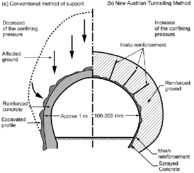
In Austria was developed a method of tunnelling design, between 1957 and 1965, the (New) Austrian Tunnelling Method (NATM). That is a technique for supporting underground galleries and tunnels. The NATM integrates the principles of the behavior of rock masses under load and monitoring the performance of underground construction during construction (fig. 1.3)
Fig 1.3 Schematic comparison of the New Austrian Tunnelling Method and a traditional method of supporting an underground gallery (from Bruce and Jewell, 1986)
The design’s idea is to excavate the tunnel and immediately after that, put steels bar to reinforce the ground and then grout them to achieve a perfect anchorage and meanwhile spray concrete reinforced with steel wire meshes provides primary support realizing a perfect rigid facing (where used). That minimizes the lining deformations and creates a resisting ring-like and in firsts
17
designs it was possible to monitor the deformation and the stresses developing in the structure, hence to improving the knowledge on the structure’s behavior and its design.
Using this method is possible to achieve to a better result, building a tunnel lining thinner than those built with conventional method of support.
Soon were built other structures composed by the inclusion of steel bars in rocks, and due to its good behavior in different kind of rocks, this technique was started to be used with soil reinforcement.
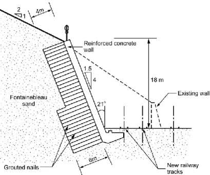
Some trials were made up to the first (reported) structure in 1972, built at Versailles. It is an application of passive inclusions in a soil cut which used closely spaced short grouted nails 4m or 6m long (fig. 1.4). This was an 18 meter high wall, with a 70 degrees slope, in Fontainebleau dense sand. It could be considered the first soil nailing structure.
Fig. 1.4 Section through the first soil-nailed wall in the world, built at Versailles, France, in 1972/73 (from Clouterre, 1991)
18
The development of these techniques involved many countries: the first orderly/systematic research about soil nailing was developed in Germany, concerning the “Bodenvernagelung Programme” (1975 – 1979) made by Gässler and Gudheus, who made a lot of studies on this topic; after that, similar programmes were made in the US and in France (Programme Clouterre): this research programme included experiments in different soils, with different type of nails and different techniques of nail inclusion, to study the real behaviour of this kind of structures. The results of this research were published in 1991 and form the basis of the soil-nailing design approach used in France and adopted in other countries.
It is possible to say that soil nailing technique is widespread used all over the world. Studies and researches, from Germany to France, from Japan to the USA and the UK, have contributed to the development of this technique, which due to its low impact on the environment and cost-effectiveness, is achieving a fundamental role in the geotechnical applications.
1.4 Development of soil nailing in the UK
The development of soil nailing in the UK has been relatively slow. The main reason was a concern about the long term durability of the nails and about the role of shear and bending in the stability in this kind of structures.
Many studies were carried out by UK’s universities and researches institutions like TRL (Transport Research Laboratory) up to 1993, to discovered and study the principles of the behaviour of these structures to find and improve new analytical methods.
So, the development of this technique was totally different than in France and Germany. That is due to the use of soil nailing in existing slope rather than new constructions. This reflects the typical UK’s way of thinking that consists in more effort given to remedial works and maintenance than to new construction.
19
Flexible and soft facing have been used much more extensively in the UK than in France or Germany, this is due to its involvement with sustainable remediation existing slopes. With the aim of this types of facing it is possible to guarantee the growth of vegetation that could be an important factor for both the facing’s stability and its visual appearance.
The use of this technique looks to increase in the future and it has become widespread all over the UK, often as part of new infrastructure work or as remedial works to existing infrastructure. The recent works for the Channel Tunnel Rail Link, the M6 Toll Road and the A3 Hindhead Tunnel Scheme have included several soil nailing applications.
1.5 Application of soil nailing
This technique of soil improvement can be used in:
Stabilisation of existing retaining walls;
Stabilisation of existing (unstable) slopes e.g.:
Natural slopes: soil nailing can be used to stabilise natural slopes. For example at Dolywern, north Wales, in 1986 a 10 m-high slope was stabilised using seven rows of soil nails (Barley, 1992);
20
Railway embankments: stabilisation of the side slope of existing railway embankments is currently the largest single application of soil nailing in the UK. Soil nailing can be a good solution where access is difficult, because drilling equipment mounted on long reach excavators can sit at the toe of the embankment slope and temporary works are minimal. Self-drilled nails are commonly used on the majority of railway earthwork stabilisation sites in the UK for the following reason:
easy access; rapid installation.
Railway cuttings;
Fig. 1.6 Railway cuttings
Highway embankments and cuttings; Embankment dams;
21
1.6 Aspects of ground conditions relevant to soil nailing
Not all soils are suitable for nailing. It is important to know and understand the characteristics of the soil that will be managed and worked, therefore a well define site investigation is required.
There are many problems that could affect the behaviour of the soil, particularly during construction and in the long term.
It is possible to divide soil in three main categories:
Cohesive soils;
Granular soils;
Soft/weak rocks.
The aim of designers, after the study of geological and hydrogeological soil condition is to identify the specific risk and the best suitability of soil nailing. It is also important to study the ground condition that governs the application of soil nailing. Soil nailing is considered a cost-effective solution if the shear strength developed by the soil is sufficient and it works as solution if the bond generated between the nail and the soil into which is installed is adequate.
Soil nailing technique gradually progresses down the slope: a row of nails in installed in a bench cut with a height of 1-2 metres and it needs to stay unsupported until the nail have been installed. So it is necessary that the bench cut hence the soil, has sufficient apparent cohesion, hence shear strength.
22
1.6.1 Cohesive soils
Soil nailing is unsuitable for soft clays and silt. That is due to the low shear strength developed in this type of soil hence it provides low bond strength as well as the impossibility to maintain temporary stability. Deformations are also difficult to control, they could be really excessive and the maintenance of the stability of the structures would become unsustainable in economical and time terms.
Differently, firm to stiff clays are suitable for soil nailing because their un-drained shear strength is greater than 50 kPa and provides sufficient bond strength, particularly in slope where tension forces are quite low.
In dry condition they also provide enough stand-up time for excavation of benches and they also provide good bore stability for drilled and grouted nails without the need for casing.
There are some particular problems that would occur in cohesive soils. These are shrinking and swelling and they usually affect high plasticity and over consolidated clays subjected to change their volume very easily because of their mineral composition.
Cohesive soil structures suffer deterioration at the crest and the face because the repeated seasonal wetting and drying causes shrinking and swelling. High plasticity clays are more inclined to suffer these problems than low plasticity ones.
Particular care is required to ensure that nail spacing, head plate dimension and facing stiffness are all sufficient to avoid gradual degradation of the nail system which could lead to progressive failure.
23
1.6.2 Granular soils
Because of their high angle of shearing resisting resulting in a strong bond, granular soils are well suited to soil nail applications. It is required to pay attention to the short term stability because it is possible that granular soil do not provide sufficient cutting stability in the short term causing unstability in the benches. In many cases, where soils are unsaturated, suctions will provide temporary stability thanks to their cohesion properties.
Particular attention must be given to the presence of ground water that can destroy the apparent cohesion.
1.6.3 Weak rocks
Weak rock are well suited for soil nailing because they provide good shear resistance hence good bond strength. They provide also good stand-up time of excavated forces. It is important to pay attention with the joints because they could contain low strength fine material and the structure could occur to an unstable state, both in short and long term.
1.6.5 Groundwater
For most soil types, soil nails are not suited to applications below the water table and should be installed from a dry excavation.
Groundwater can have adverse effect on:
Bond;
Durability of the nail and the integrity of the grout;
24
Stability of temporary excavations;
Overall stability of slopes;
Seepage of groundwater through the unsupported cut face can lead to instability of temporary excavations, particularly in predominantly granular soils or cohesive soils (fig. 1.7).
Fig. 1.7 Effect of ground water on wall facing
Groundwater at depth can still introduce difficulties, both in terms of installation and in the long term performance of the nails. Groundwater flow through the soil can lead to instability of nail bores, unless casings are employed.
Effects of long term change in ground water conditions on the soil nailing scheme. This may include climate charge, different rates of abstraction from aquifers or changes in groundwater regime.
A rise in groundwater is often associated with old mining areas where groundwater pumping of the mines has ceased an equilibrium of the natural water table is gradually being restored.
25
2. KEY MECHANISMS OF BEHAVIOUR
The reinforcements used in reinforced earth systems have the primary function to develop tensile strength to collaborate in the whole structure behaviour, so their maximum efficiency is achieved by placing them in the same direction of principal strains axes.
Figure 2.1: Effects of reinforcement of a sample of soil in triaxial conditions (from Schloesser et al., 1972).
The usefulness of reinforcing element can also be evaluated with reference to a simple scheme in which the reinforcement intercepts a failure surface (fig. 2.1). The beneficial effects of the presence of a tensile stressed element are:
the component of stress in the reinforcement (PR) normal to the surface scroll (PRsen) contributes positively to the shear strength to increase the normal strain forces;
the component of stress in the reinforcement (PR) parallel to the surface scroll (PRcos) contributes positively to the efforts for reduce shear forces.
26
Figure 2.2: Effects of reinforcement on both sides of a fracture surface of the ground.
The behaviour of a reinforced soil mass is typical of composite materials whose mutual interactions are developed by friction. So, it depends primarily by two variables that govern the shear behaviour of the uncemented bodies: friction angle (in this case the interface between reinforcement and soil) and normal stress acting on the interface’s surface (for reinforcement plans is usually the vertical tension or a component).
The stress states induced by these mechanisms of reinforcement interaction are: a tension or compression state due to longitudinal interaction, and a shear and bending state due to transverse interaction.
The interaction between soil and inclusions has two beneficial effects: reduced deformability and an increase in shear strength. Stability is satisfied by the mobilisation of shear stresses at the soil/nail interface.
27
2.1 Transfer of loads
Soil nailing technique improves the stability of an excavation or a slope mainly through the mobilization of tensile stresses in the inclusions that is developed through the friction interaction between soil and reinforcement and for the reaction of the head of the nail and the facing.
As a result of small deformation occurring in the facing, the nail is subject to displacements both in the axial and transverse direction to its axis that induce stress. The axial displacements are generated by tensile stresses occur in the nail, which can reach the maximum limit value equal to the maximum frictional resistance that can occur in the soil-reinforcement interface, which is called pullout resistance. The tensile stresses contribute to increase the soil resistance, whether absorbing part of the shear stress or causing an increase of normal stress along the potential failure surface.
Lateral displacements develop transverse forces on the nail; these forces achieve the maximum limit equal to the bearing capacity of the soil determined in the same way of piles loaded by horizontal forces. Shear and bending forces are influenced by the inclination and the stiffness of the nail itself. That is due to lateral displacements arising in the nail.
Because of its thinness that characterizes nail, reinforcing actions related to shear and bending are limited by low bending resistance and are usually not considered (FHWA 1998). They do not occur under deformations of less than 0.3 – 0.4 per cent of the wall or slope height.
28
The tensile stress generated in the nails has parabolic development and its peak, which coincides with the hypothetical failure surface, separates the soil-nailing system in two areas: it is greater than the stress transferred to the facing (as shown in figure 2.3):
ACTIVE ZONE: Zone of potential failure where the friction forces along the nail are directed towards the facing and act to remove the reinforcement;
RESISTANT ZONE: passive zone, where friction forces are directed toward the interior of the slope, preventing outward movement of the nail and, therefore they minimize displacements even in the active zone.
Often we consider the soil nails as the elements that bind in a certain way the active region with the passive and the concept of two distinct and separated areas, however, is only an idealization to simplify the model. There is actually a complex failure zone subject to shear distortion, and also the failure surface is influenced by the presence of joints where it is evident a beginning of detachment.
Soil nail head together with the facing perform primarily a confinement function minimizing possible deformations of the soil, with a consequent growth of the effective tension and the shear strength of the soil behind the nail head, and help to avoid preventive local ruptures near the surface of the wall. As evident from the forces distribution the strain hanging on the facing and on the nail heads is less than the maximum achievable value because of the interaction between nail and soil even in the active region, hence the forces at the nail head will never be as high as the maximum resistance developed further down the nail. In this way, the facing may have not bearing functions but only aims for protection and containment.
29
Figure 2.3: Active zone and resistant zone, and stress distribution in nails
The pullout resistance is provided by the part of the nail located in the passive zone and the mobilization of its resistance depends on several factors. Theoretically, the shear strength acting between the soil nail and the surrounding soil depends on the strain contact and the factor of friction. When a soil nail is drilled and filled with grout, the drilling process reduces significantly the radial tension on drilling perforation, the hole remains stable due to arching.
30
2.2 Failure domain of the nail
Although the soil nails are mainly stimulated by tensile stresses, as a result of big displacements and because they cross the failure surface, they are also subjected to shear and bending stresses that deform the element into a “S” shape. The position on the nail where the stresses are greater are two points: “A” (Fig 2.4) where the value of the bending is maximum and where they are at the same distance (symmetrically) from the failure surface, and point “B” where the nail intersects the failure surface, which is precisely the point where the maximum shear stress is acting (and therefore with none bending stresses). The shear and bending stresses are uniquely related to each other, once defined load conditions, and the tensile stress generated in the nail is totally independent.
Figure 2.4: Loads and stresses subjected by the nails on the failure surface (Jewell, 1990 edited by Evangelista 1995), where Tn is the tensile stress along the nail, Tt is the maximum
shear stress, Mmax is the maximum bending stress.
These shear and bending forces, although they are usually ignored in design phase, affect the maximum resistance which can be provided by the soil nail and depends on the rupture of the nail itself. The reinforcement ability to support these other types of stress as well, can increases the shear strength of the soil. However, ignoring development of shear and bending in design is
31
conservative. The value of the maximum force the nail is required to carry can be obtained from analysis on possible states of stress that can be developed simultaneously. The domain of possible states of stress in the plan Tn-Tt for a nail was defined by Schlosser (1982) by using four failure criteria. Based on the Mohr's circle, Jewell et al. (1987) proposed a relationship for the calculation of the strain forces developed on the nail as a function of its angle of inclination compared to the failure surface.
This report, confirmed by experimental results of shear tests on sand reinforced with bar embedded in different inclinations, is indicative of the relationship between the maximum tensile stress in the nail and its angle of inclination β (Fig. 2.5), the soil shear strength increases with the angle β until it reaches up to 30° and then decreases. The results showed that the presence of reinforcement produces a re-orientation of the principal directions of deformation of the soil. The deformation of the soil in the vicinity of the reinforcement is less than the deformation occurring in a unreinforced soil, because the presence of the reinforcement inhibits the formation of failure surfaces. The shear strength of the soil increases if the reinforcement has the same orientation of the main directions of strain forces, but it decreases when it follows the orientation of the compression forces.
Figure 2.5: Variation of shear strength as a function of the angle of inclination β of the nail, with a rough reinforcement (Jewell et al., 1987)
32
As written above, the effect of reinforcement is influenced by the angle of installation, Gassler identified three groups that can divided the soil nail types (Gassler, 1992): those that are installed horizontally, working mainly under the action of tensile; soil nailing structures with a small bending stiffness that are installed with a slight inclination compared to the failure surface, and that work, however, mainly under the action of tensile forces; reinforcements with high bending resistance that are installed almost perpendicular to the slipping surface and that develop shear strength if important displacements are generated.
The displacements required to mobilize the shear and bending forces in nails are bigger than those that allow to achieve the maximum tensile strength and ultimate shear strength in the soil. For this reason, during the structure serviceability, due to the reduced movements, their contribution in the total resistance generated by the reinforcement is insignificant. Therefore, for shear and bending to be taken in account the designer needs to verify that the deformations will be sufficient to mobilise these resistances.
33
2.3 Mechanisms of failure and design methods for soil nailing
The detailed design of soil nailed slopes or walls is based on information about the soil, groundwater conditions, loads, geometry and type of soil nail to be used. Detailed design is undertaken to fulfil the following main requirements:
to satisfy equilibrium of forces and moments (strength and stability)
to limit displacements (serviceability)
to maintain this performance criteria throughout the specified design life (durability)
The design of this kind of structures follows steps that depend each other like every other geotechnical structure. For this technique they consist in:
1) define geometry and design cross-sections;
2) define surcharges and loads;
3) define ground model;
4) define groundwater and design of drainage;
5) design codes and design methods;
6) define characteristic soil strengths;
7) determination of design soil parameters and design loads;
8) internal stability and pullout resistance.
9) nail tendon design;
10) ground aggressivity and corrosion protection;
11) internal and external stability checks;
12) design of facing and head plates;
34
The firsts six steps are well defined above. This chapter treated the following steps.
In stability analysis of an excavation or a slope of primary importance is the identification of all possible sliding surfaces, in those surfaces is exceed the soil capacity to resist shear forces. The sliding surface, as seen, divides the system into an active and a passive zone, it is usually identified taking into account the mechanical properties of the soil and possible overload. The shear strength of the soil is mobilized along this surface, which can be expressed in terms of effective stress, such as τ= c'+ σ' tanϕ' according to the Mohr Coulomb failure criterion. If the shear strength available is less than that required to prevent that the active zone is subjected to a relative displacements in relation with the passive zone, the soil breaks along the failure surface; conversely the excavation or a slope is stable.
Soil nailing structures, because of the presence of reinforcement, may be affected by failure mechanisms both internal and external, the firsts regards the failure which may subject the individual nail; in the seconds soil nail reinforcement and soil are considered as a single monolithic system that can be affected by a slipping surface. When they occur at the same time a mixed failure is happening.
The main types of internal failure that may affect the soil nail, both in active and passive zone, are: the pullout failure of reinforcement for loss of friction between the soil nail and the surrounding soil. Exceeding the maximum load bearing capacity of the soil due to excessive movement of the soil nail, the nail rupture due to excess tensile stresses or to the combined action of shear and bending forces; structural failures due to the rupture of the soil nail head or due to the rupture of the facing.
External failure of the soil nailing system occur when sliding mechanisms along the slipping surfaces, together with rotation and translation mechanisms occur in the soil-reinforcement complex.
35
Fig 2.6 Possible mechanisms of failure of an excavation with the technique of reinforced soil nailing
There are several methods proposed for the soil-nailing system design based on the analysis of stability with the limit equilibrium method and on the use of partial safety factors. In the analysis of equilibrium stability limit, different assumptions about the potential slipping surface can be made and as well as forces to break the nail. Failure surfaces are variable from method to another one in a wide range: those that are linear methods that assume the formation of a slipping wedge or those bi – linear, logarithmic spiral and circular type; much discussed is the shear and bending forces influence in the soil nail system stability, because it’s of minor importance compared to tensile stresses (<10%), as already mentioned. In many cases they also can be overlooked.
The methods as well as the shape of the failure surface and for the stress state in the nail, differ among themselves for the factors of safety adopted: some methods, oldest ones and already outdated, referring to a single factor of global security calculated with the available resistance and acting forces ratio.
Other methods, more sophisticated but also more reliable, are based on several factors that take into account the possible failure type which may be locally subject a soil nailed slope and the various factors that may affect in some way the system stability.
In the latter approach is verified that the destabilising forces are less than the resistances, , where S = τmob is equal to the resistance acting along the slipping surface and R = τs + ΔτNL + ΔτNT is the sum of the resistance respectively with the absence of strong nails and contributions due to
36
longitudinal and transverse components of the strain force developed by the nails to the failure surface.
When the structures, may be affected by deformation to a lesser extent than those that would result in the collapse of the system, they are in a state called serviceability condition and, however, must also be verified the rupture condition. The deformations which can occur in the system cannot be catastrophic, but they can cause nevertheless a loss of structure’s functionality as well as damage to surrounding structures or infrastructures: it must be ensured that the weaknesses developed in the excavation are acceptable as well as the reinforcements’ deformation. The structure’s functionality can be a problem in long-term. The displacements of the excavation shall be such as not to cause disturbance to nearby buildings or infrastructures, failure of the facing, unequal loads’ distribution between the nails, which then can lead to rupture of the most loaded reinforcement, ground-breaking strength. Several trial fields have been allowed, through continuous monitoring, to estimate horizontal and vertical displacements at the top of the structure. They may be considered acceptable if they are of the order of 0.1 to 0.4% of the height of the slope (Clouterre, 1991; Srinivasa et al.2002 ).
The different published design methods favour slip surfaces of varying geometry. In order to ensure a safe design the most critical of these should be identified. For long term serviceability the critical slip surface should be calculated taking the possible long term soil strengths into account. The published design methods, from a number of different countries, are discussed below together with their main recommendations. The different national methods are often developed in parallel and are based on differing design philosophies. Hence the assumptions which each method makes can be very different.
37
2.4 Limit state design
When a soil-nailed wall or slope, or part of it, fails to satisfy any of its performance criteria, the wall or slope is deemed to have reached a limit state. Structures’ stability can’t be achieved also for deformations problem. Predicting deformations of soil-nailed walls and slope can be difficult. It is common to introduce partial factor of safety for a correct and safety design.
2.4.1 Ultimate limit state
Ultimate limit states are generally associated with total collapse or failure. It is achieved when disturbing forces exceed the available stabilising forces at any particular moment. The limit state can occurs in:
• External stability – the failure falls outside the zone of reinforcement.
• Internal stability – mechanical failure of the nail elements, generally more than one element, pullout may also result in internal failure of the soil nailed system. The nature of soil nailing allows transfer of load from one nail to another if an individual failure occurs.
• Compound stability – a possible mixture of external and internal stability.
The retaining wall system should be designed to exhibit sufficient ductility in approaching geotechnical limit states to give visible warning of failure. The ultimate state design requires to consider the likely hazard and risk could occur in the slope during is design life. For soil-nailed slopes and wall, these are:
External stability hazards
loss of overall stability at any stage; rotation;
38
sliding;
foundation failure;
Internal stability hazards
pullout of nails through failure at the soil/nail interface; rupture of the soil nails
toppling of the facing
bending or punching failure of structural facings punching or bearing failure of head plates failure of soil between the nails
bearing capacity of structural failure of head bearing pads.
39
2.4.2 Serviceability limit state
A serviceability failure occurs if a structure deforms more than an allowable value. This type of failure is not necessarily catastrophic but could be hazardous to surrounding structures.
The serviceability state must be verified in:
External stability – settlement of the slope foundation
Internal stability – post construction strain in the reinforcement and creep of soil
The design life is the period for which all serviceability criteria need to be met. Common serviceability limit states may eventually lead to ultimate limit state failure through progressive deterioration:
Strains or movement of the facing that could affect the visual appearance of the facing or result;
Deformations in the facing that could affect the serviceability of any adjacent structures, service or infrastructure;
Cracking of hard facings (when used);
Excessive bulging of soft or flexible facings (where used).
Limits are set as to what would be acceptable to limit damage, or it may be human perception of what is dangerous. The only method to check the displacements with a soil nail system is numerical analysis.
40
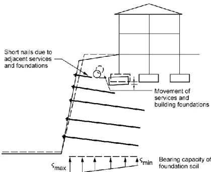
Fig 2.8 Illustrations of serviceability limit states for soil-nailed slopes and walls
2. 5 Conceptual design
The design of a soil-nailed wall or slope comprises two main stages: conceptual, which is followed by detailed design.
The first consists to identify the characteristics and the properties that describe the site used for the work. That includes the study of the site in its global properties and the accurate study of the soil characterizing the site. Both require tests, either lab or in-situ test.
Conceptual design is only the first stage in any project involving soil-nailed walls or slopes.
The factors to be considered for soil nailing are:
Risk based approach;
Characterisation of the ground;
Groundwater;
41
Site constraints.
Deformation.
2.5.1 Layout and spacing of nails.
The conceptual design concludes with the preliminary layout, angle of installation and lengths of the nails. The most important factors that influence these are:
Ground strength;
Height of face;
Angle of face;
Type of nail (drilled and grouted, or driven);
Unit pullout resistance;
Environmental constraints;
Facing type (rigid or flexible).
Generally, nails are installed in rows at a slight inclination below the horizontal of between 5 and 20. For grouted nails, this is to permit gravity installation of the grout. While it is most practicable to make all the nails inclined at the same angle to the horizontal, different layouts may be required in special cases.
The spacing of the soil nails reflects the choice of facing type as well as overall stability requirements. Maximum horizontal and vertical nail spacing are typically in the range of 1.0 – 2.0 m, that is due to the behaviour of the soil as a coherent reinforced soil block becoming insignificant if the area covered by one nail is upper than 6mq in a rigid facing structure or upper than 2-4mq for a flexible facing structure (Phear et al., 2005).
42
2.5.2 Nail orientation
It is important to define the nail orientation to achieve to a cost effective and efficient. Many researches have been carried out to understand and find which nails’ configuration could be the most effective, hence which practical angle of installation it is better to use in a soil nailed slope.
One important study by Johnson et al (2002) has shown that for a nail intersecting a failure plane inclined at 60 to the horizontal in a soil with an internal friction angle ϕ’ of 25, the most effective nail inclination was 35° and it is possible to see this experience applied to a 6 metres high slope reinforced with a single 6 metres long. It is possible to see how the nail installed at optimum tensile has a short length (2.3m) in the resistant zone and little depth (1.2m) of overburden. Although the nail installed at 15 below the horizontal has an efficiency of 64% of the nail installed at the optimum angle, it has nearly twice the length in the resistant zone and more than four times the average overburden.
Based on the above theoretical analysis, it would appear that the optimum design angle is between about 10 and 15 below the horizontal (fig. 2.9).
43
2.5.3 Nail tendon design
The design tensile strength of the nail tendon (Tnd) is calculated as follows:
s, a partial factor for reinforcement material, is 1.05 for steel in tension and about 1.3 for geosynthetics (Eurocode7, 2004). As and fy should be the values applicable at the end of the design life.
2.5.4 Detailed design
It is important to say that many codes and methods exist and every nation still uses its guidelines and norms but nowadays the principal guideline for European design is the Eurocode 7 .
For both serviceability limit state and ultimate state cases, design soil strengths are obtained by dividing (and so reducing) the characteristic strengths by a partial factor as follows:
44
2.5.5 Pullout resistance
The pullout resistance of a soil nail is dependent upon the overburden pressure of the soil, the vertical and lateral pressure around the nail and the nail/soil interface friction. The design nail resistance is the lowest of the following:
1) The pullout resistance between the soil nail and the ground.
2) The pullout resistance between the nail tendon and the grout (for grouted nails).
If the aim is to achieve a ductile slope failure mechanism, Criterion 1 is preferred.
The ability of a soil nail to generate sufficient pullout resistance (soil/nail) is of fundamental importance to the stability of a soil-nailed slope or wall. The ultimate pullout resistance of a soil nail is a function of the following:
Soil type;
Surface roughness;
Drilling or installation technique;
Time that the drillhole is left open and ungrouted (if this is too long, it will probably reduce the ultimate pullout resistance)
Grout pressure (if grouted);
Nail diameter;
Nail length in the active zone;
Nail length in the resistant zone;
Elasticity of the tendon;
Time (for soils susceptible to creep action);
Presence of groundwater
There are at least five methods of determining the pullout resistance, as discussed below.
45
1. Empirical correlations and charts. 2. Pullout test.
3. Undrained shear strength methods (only for cohesive soil). 4. Effective stress methods (for cohesive and for granular soils). 5. From pressumeter tests.
Confirmation of ultimate pullout resistance is particularly important since a large proportion of failures of soil-nailed slopes and walls results from overestimation of the pullout resistance of the nails. Site pullout tests should be considered to be an extension of the design process.
2.5.6 External stability checks
The types of internal stability are described in par. 2.4.
The following external failure modes should be considered in the analysis of soil-nailed walls or slopes:
Overall stability;
Sliding failure;
Bearing failure.
“Sliding stability”
Analysis of sliding stability considers the ability of soil-nailed walls or steep slopes to resist sliding along the base of the soil-nailed block in response to lateral earth pressure behind it. Sliding failure may occur when the lateral earth pressure exceed the sliding resistance along the base. Such failures can occur if there is a weak horizontal, or nearly horizontal, seam or zone at or slightly below the toe of the wall or slope.
46
“Bearing capacity”
Very rarely, bearing capacity may be a concern when a soil-nailed wall or steep slope is excavated in soft fine-grained soils. Since the soil-nailed block does not extend below the base of excavation, the unbalanced load caused by the excavation may cause the base of the excavation to heave. This may result in a bearing capacity failure of the foundation of the wall or slope.
47
3. FACING
Where soil nail are used to stabilise an existing slope, or to construct a new slope, they do not stabilise the surface soil. This is done by means of head plates and /or a facing. Separate measures to retain the surface (and near-surface) soil need to be adopted and integrated with the soil nail system. The facing system (hard, flexible or soft) can modify the internal failure mechanisms. The larger and smaller components of load transfer to a working soil nail are summarised in fig(3.1).
Fig 3.1 Comparison of the larger and smaller components of load transfer between hard and flexible facing system
48
As the bond stresses transferred to the facing varies depending on the type and stiffness of facing.
It is important to observe the empirical correlation based on previous experience, collected by Bruce and Jewell (1987), of different features of the different types of facing .
They derived four parameters to allow comparison between the design of different projects. These are:
Length ratio (L/H) Bond ratio (Br) Strength ratio (Sr) Performance ratio (Pr)
The most useful of these ratios for conceptual design is the length ratio and examples are presented from Table 3.1 to Table 3.3, there appears to be little correlation between slope angle, length ratio, area per nail and material type. That could be due to the fact that there is confusion over design methods.