Alma Mater Studiorum · Universita
` di Bologna
Scuola di Scienze
Corso di Laurea Magistrale in Fisica
Magnesium based nanoparticles
for hydrogen storage
Relatore:
Dott. Luca Pasquini
Presentata da:
Federico D'Amico
Sessione II
3
Contents
Abstract
... 6CHAPTER I. Hydrogen economy: perspectives and problems
. ... 7An alarming situation ... 7
A new hope: hydrogen ... 8
How to store hydrogen: different paths ...10
Lolland: the future has become reality ...12
CHAPTER II. Hydrogen and metals
...13Introduction ...13
Phase diagrams ...13
Solid solution at low hydrogen concentration ...14
Solid solution at high hydrogen concentration ...16
Hydrides structure ...18
Hydride formation thermodynamics ...19
Terminal solubility ...22
Destabilization of Mg-H system ...23
CHAPTER III. Hydrogen
...29General features ...29
Hydrogen molecule according to quantum mechanics ...31
CHAPTER IV. Materials
...35Magnesium ...35
Magnesium oxide ...36
Palladium ...38
CHAPTER V. Inert Gas Condensation
...41General features ...41
Experimental setup ...41
CHAPTER VI. Nucleation theories
...45Classical nucleation theory ...45
Beyond classical theory ...46
Kinetic nucleation theory ...47
Coalescence ...48
CHAPTER VII. Devices used
...514 History ...51 General features ...51 Experimental setup ...54 TEM ...54 History ...54 General features ...55 Experimental setup ...57 XRD ...57 History ...57 General features ...58 Experimental setup ...62
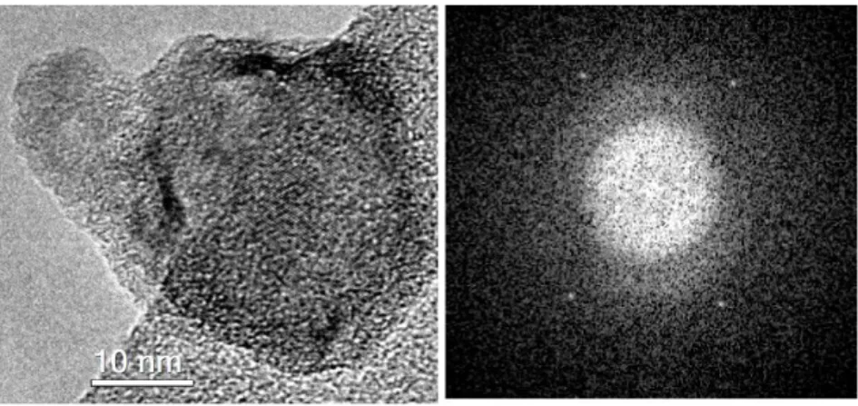
CHAPTER VIII. Samples morphologic characterization
...63From pure Mg nanoparticles to Mg/MgO systems ...63
MgO_87 ...63 MgO_88 ...66 MgO_Pd_89 ...68 MgOPd_98 ...69 MgO_95 ...71 MgO_Pd_97 ...73 XRD analysis ...76 MgO_95 ...77 MgO_93 ...78 TEM analysis ...79
CHAPTER IX. Samples subjected to hydrogenography
...84MgPd_51 ...84 MgPd_101 ...84 MgOPd_99 ...85 MgOPd_100...86
CHAPTER X. Hydrogenography
...87 General features ...87Substrate presence effects ...88
Hysteresis phenomenon ...89
Experimental setup ...90
5 MgOPd_99 2 minutes ...92 MgOPd_99 5 minutes ...94 MgPd_101 2 minutes ...95 MgPd_101 1 minute ...100 MgOPd_100 2 minutes ...103 MgOPd_100 1 minute ...106 MgPd_51 ...109
CHAPTER XI. Conclusions
...114References
...1206
Abstract
Questo lavoro riguarda la sintesi e caratterizzazione di nanoparticelle basate sul magnesio per l'immagazzinamento di idrogeno. Le nanoparticelle sono state cresciute mediante Inert Gas Condensation, una tecnica aerosol in cui il materiale viene sublimato e diretto verso i substrati tramite un flusso di gas inerte, e caratterizzate attraverso microscopia elettronica e diffrazione di raggi X. Queste operazioni sono state eseguite presso il Dipartimento di Fisica e Astronomia dell'Università di Bologna. Sono stati sintetizzati due tipi di particelle: nel primo il magnesio viene deposto direttamente sul substrato, nel secondo esso incontra un flusso di ossigeno prima di depositarsi sulla superficie. In questo modo si formano delle particelle con struttura core-shell in cui la parte interna è formata da magnesio e quella esterna dal suo ossido. La presenza di una shell consistente dovrebbe permettere, secondo il modello di deformazioni elastiche, di diminuire il valore assoluto dell'entropia di formazione dell'idruro di magnesio, condizione necessaria affinché il desorbimento di idrogeno possa avvenire in maniera più agevole rispetto a quanto non accada col materiale bulk. Tutti i campioni sono stati ricoperti di palladio, il quale favorisce la dissociazione della molecola di idrogeno. La capacità di assorbimento dell'idrogeno da parte dei campioni è stata studiata mediante idrogenografia, una tecnica ottica recentemente sviluppata in cui la quantità di gas assorbita dal materiale è legata alla variazione di trasmittanza ottica dello stesso. Le misure sono state eseguite presso l'Università Tecnica di Delft. I risultati ottenuti evidenziano che le nanoparticelle di solo magnesio mostrano dei chiari plateau di pressione corrispondenti all'assorbimento di idrogeno, tramite cui sono stati stimati i valori di entalpia di formazione. Al contrario, i campioni con struttura core-shell, la cui crescita rappresenta di per sé un risultato interessante, non presentano tale comportamento.
7
CHAPTER I. Hydrogen economy: perspectives and problems.
An alarming situation
The need for more and more energy and the dramatic necessity of respecting Earth environmental limits force mankind to find new or improve clean and renewable sources of energy.
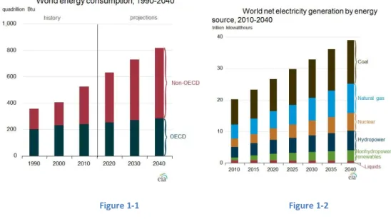
According to US Energy Information Administration [1] in 2010 just 5,3% of the whole energy production came from clean sources and global power requirement was of about 17000 TW h per year, but experts say that it will grow up to 28000 TW h per year in 2030, especially due to the economic growth of the so called BRICS (Figures 1-1 and 1-2).
The conversion from British Thermal Units and kWh is that 1 Btu stands for 0.000293 kWh.
Figure 1-1 Figure 1-2
Today's situation is alarming since most of the exploited energy comes from hydrocarbon resources: a solution that creates geopolitical tensions, a degree of pollution so critical that if we do not change our energy supplying system climate changes will cancel out mankind soon and that is forced to end, since it takes million of years to create new fossil deposits.
Being the situation so dangerous, the birth and the affirmation of an economically sustainable system based upon renewable sources appears a priority.
8
A new hope: hydrogen
Hydrogen was thought to be a fuel that could substitute gasoline for the first time in the Seventies. In 1970, during a talk at General Motors Technical Centre, J. Bockris launched the idea of an hydrogen economy [2]: a system where this gas should have replaced petroleum derivates as fuel. Actually, this simple change would not solve the environmental problem: hydrogen does not occur naturally in quantity, but it must be generated and the way this is done is a central point of the discussion.
Proponents of a world-scale hydrogen economy affirm that this solution would be cleaner, particularly in transport applications, being free from the release of pollutants. Moreover, a significant reduction in carbon dioxide emissions would be possible if carbon capture methods were utilized at the site of hydrogen production. In fact, hydrogen is just a carrier of energy. The simplest way to store and release energy is through the following reaction:
It takes place in fuel cells (Figure 1-3), systems with very high values of efficiency (till 80%-85% for devices that are able to use heat produced by the reaction, without this skill efficiency drops to about 60%-70%) and produces just water. When working at very high temperatures some polluting gasses could be released, but this inconvenient can be eliminated by specific methods.
Figure 1-3
Nowadays molecular hydrogen is mainly created from fossil sources [3] and so carbon dioxide is produced: 48% from natural gas, 30% from oil and 18% from coal. Just the 4% comes from electrolysis of water, a method that can be CO2 free. Decomposing water, since most hydrogen on Earth is bonded to oxygen in H2O, requires an external (electrical or heat) input and it would be positive if it came from clean source such as solar energy.
Hydrogen production is a large and growing industry with rates of growth of around 10% per year [4]. Two are the primary uses of hydrogen: the synthesis of ammonia, that is widely diffused in fertilizers, and the so called hydrocracking, that is a process converting heavy petroleum sources into lighter fractions.
9
Hydrogen is industrially produced from steam reforming, which uses fossil fuels such as natural gas, oil or coal: greenhouse gasses are so generated. The most widely diffused method is named Kvaerner process, from the Norwegian company that developed it in the 1980s [5]. It is also possible to use biological agents to create hydrogen, like algae or some bacteria: the former, if deprived of sulphur, creates hydrogen instead of oxygen through the normal photosynthesis, the latter extract it from hydrocarbons, together with CO2.
The process by which molecular hydrogen is split from water is named electrolysis and it has been found that it can be developed by aquatic plants too. These systems are not widely diffused due to their low efficiencies.
Current best processes have an efficiency that varies from 50% to 80% [6]: 1 kg of hydrogen requires 50 to 79 kWh of electricity that means about 3 €/kg, which is 3 up to 10 times the cost of hydrogen made from steam reformation of natural gas. Electrolysis can become cheaper using systems working at high pressure or at high temperature.
Using electricity produced by photovoltaic systems represents the cleanest way to produce hydrogen: water is broken into hydrogen and oxygen by a photoelectrochemical cell (PEC) process which is called artificial photosynthesis. In 1983 direct water splitting was demonstrated with a low cost thin film of amorphous silicon multi-junction sheet immersed in water itself [7]. This pathway is very interesting and research goes on developing higher and higher efficiency multi-junction cell technology.
Sun energy can be exploited in another way too. It was said that high temperatures are required to split hydrogen from water: it can be done exploiting concentrating solar plants, capable to heat water up to 1200°C.
Production is just the first step toward a hydrogen economy: storing the gas is a critical point and will be the core of this work.
In 2009 the US Department of Energy set the performances that any hydrogen storage system should have in order to develop an economically sustainable fuel distribution. Data are shown in Table 1 [2].
Table 1
Unit
2010
2015
Final
Gravimetric capacity wt% kWh/kg 4.5 1.5 5.5 1.8 7.5 2.5 Volumetric capacity kg/m3 kWh/m3 28 900 40 1300 70 230010 Minimal/maximal working temperature °C -30/50 -40/60 -40/60 Purity % (dry) 99.97 99.97 99.97 Supply time (for 5 kg of hydrogen) minutes 4.2 3.3 2.5
How to store hydrogen: different paths
Nowadays there are several methods pointed as solution to this problem, each of one exploiting different physical phenomena:
- Physical containment;
- Physical adsorption;
- Chemical bound.
Molecular hydrogen has very high energy density on mass basis, but at ambient conditions it has very low energy density by volume, so the first solution tries to improve this ratio by pressurization or liquefaction. Achieving high pressures needs a great use of external energy for the compression. Liquid hydrogen is formed cooling the gas down to 20.28 K. Cryogenic storage requires large energies and very complex technologies and presents the problem of the boil off. Moreover, ice may develop in the device used to contain hydrogen, corroding it.
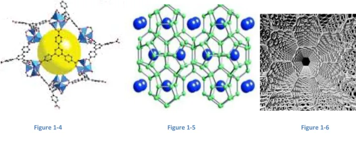
The second approach is to absorb molecular hydrogen on the surface of a solid storage material, without hydrogen dissociation. In this way, the system does not suffer from limitations of gas kinetics. The very central problem of this solution is the low quantity of hydrogen stored and the low temperature. In order to improve physisorption, materials should have a good density of H2 per surface unit and a large active surface. The best candidates to develop this approach are Metal Organic Frameworks (Figure 1-4), activated carbon, hydrogen clathrate hydrate (Figure 1-5) and nanostructured carbons (Figure 1-6 shows graphite nanotubes) [8].
11
Figure 1-4 Figure 1-5 Figure 1-6
The last one is what will be investigated in this work: hydrogen stored as a chemical hydride in some compounds. This solution is thought to be efficient for matters as safety, easiness of transport and mass and volume density problems. Storing and ejecting H2 molecules can be controlled by kinetics and heat control. Current barriers to practical and spread use are the values of pressure and temperature that must be reached in order to release or accumulate hydrogen, even if several compounds able to satisfy the US Department of Energy objectives are already known. Research goals are to lower pressure and temperature needed, make reactions faster and better volume and energy densities, keeping attention on costs.
A large scale hydrogen economy cannot become reality without an efficient infrastructure system. It would be made up of pipelines and filling stations. If these are far from the pipeline network, they must be supplied by trucks which carry hydrogen (liquid, compressed or stored in hydrides). Since hydrogen corrodes steel, pipelines must be covered internally by special coatings that are already known. Even if they are expensive and still not competitive with petroleum or natural gas networks, pipelines represent the cheapest way to make hydrogen move from a point to another.
Pipelines are essential in a scheme that expects a few hydrogen producing plants, but they could be in principle much less important if small and diffuse producing sites were adopted. In any case, it is reasonable that both approaches would be adopted, if hydrogen took the place of gasoline: centralized primary energy plants would have higher hydrogen production efficiency but they would require long range transportation networks, with the linked problems of hydrogen damage to and leak from the lines of distribution. On the contrary, small local plants would have lower production efficiency, but the reduced use of pipelines could result in a more efficient scheme in terms of primary energy used.
Hydrogen has one of the widest explosive and ignition mix range with air of all the gasses, so safety is a central concern. Whatever the mix between air and hydrogen, an explosion is very probable. Moreover,
12
pure hydrogen-oxygen flames burn in the region of the ultraviolet, so a flame detector is necessary and hydrogen is also odourless, a feature that makes harder the gas detection. The European Commission launched the first higher educational program in hydrogen safety engineering at the University of Ulster.
Lolland: the future has become reality
European Union is cutting edge about hydrogen economy: Lolland Hydrogen Community is the first full-scale Hydrogen Community Demonstration facility for residential Fuel Cell Combined Heat and Power (CHP) [9]. Lolland is an island in Denmark where wind is abundant. This factor makes possible a large production of energy from wind mills, so copious that more than the 50% of the energy produced is in excess. For this reason it is stored in the form of hydrogen and used for residential and industrial facilities. Hydrogen is produced by electrolysis of water together with oxygen. The oxygen is used in the municipal water treatment plant nearby to speed up the biological process. Hydrogen is stored in low-pressure storage tanks at six bars and fuels two PEM Fuel Cell Micro Combined Heat and Power (CHP) stations.
13
CHAPTER II. Hydrogen and metals
Introduction
Hydrogen is a very reactive molecule and it forms a wide range of different chemical bonds. It is possible to classify different compounds from the kind of interaction with hydrogen:
Saline hydrides: they are made up of hydrogen and alkali and alkali-earth elements, having low values of electronegativity, so that hydrogen forms ionic compounds (LiH, NaH, MgH2, BeH2, etc.); Hydrogen-bonded molecular crystals: hydrogen reacts with atoms or radicals with high
electronegativity values (2,5-dihydroxybenzoquinone (DpH), 2,5-dichloro-3,6-dihydroxybenzoquinone (DpC1), etc.);
Covalent molecules and crystals: they are formed by hydrogen and an element that has got a similar electronegativity value (CH4, NH3, SiH4, HF, etc.);
Metallic hydrides: they are made up of hydrogen interstitial atoms in transition metals, lanthanides and actinides (NiHx, VH, VH2, CrH, CeH2, etc.).
Note that heavy simple metals do not form any kind of compound with hydrogen. Moreover, metallic hydrides exist over large ranges of non-stoichiometric compositions, since hydrogen occupies interstitial sites and the quantity of gas included into the metal changes as the thermodynamic conditions do. In many cases the host material changes its structure in order to accommodate hydrogen.
Phase diagrams
Phase diagrams are a very useful instrument to study binary systems, such as those in which H atoms bond with M (metallic) ones. It is useful to define the variable as the ratio of H concentration over the one of M. In other words:
When T is on the abscissa, it is possible to speak of diagrams. Changes in temperature involve changes in the thermodynamic equilibrium between the sample and the surrounding atmosphere. For this reason, to draw correct phase diagrams, it is more useful to study phase diagrams at different temperatures, kept constant during a measurement. The result is the so called pressure-concentration-isotherms ( ) in which the phase boundary is determined by the inflection points of the diagram.
14
At each temperature under some critical one there is a plateau between the two inflection points. It means that two different phases coexist at the same time. Sometimes it is possible to observe a hysteresis, during a heating-cooling cycle. In this case, desorption branches are commonly taken as representative of the equilibrium condition. Moreover, it is only over some specific temperatures that the hydrogen diffusion process through the bulk is activated: it is a common practice to make the sample undergo heating-cooling cycles, in order to make it permeable.
Figure 2-1 shows a diagram (system of H and Pd) and Figure 2-2 a one at different temperatures (D and Pd).
Figure 2-1 Figure 2-2
Solid solution at low hydrogen concentration
At low hydrogen concentrations, all have a common slope, proportional to the pressure square root. This relation is known as Sievert's law and it can be explained intuitively considering that hydrogen molecules are dissociated into two atoms entering the host metal. Hydrogen solubility is a thermally activated phenomenon, so the expression for the solubility is
15
Where ΔSs is the entropy of solution referred to T and and ΔHs the enthalpy of solution and stands for
the change of entropy or enthalpy of hydrogen when it enters the host material.
When thermodynamic equilibrium is achieved, the further expression stands:
Calling the chemical potential of the gas phase and the one in the solid phase, it is equivalent to say
For solid solution containing n hydrogen atoms, it is possible to distinguish the configurational (labelled by
c) and non-configurational (nc) terms of the Gibbs free energy:
It is easy to derive the chemical potential, once defined r=N/N0 as the number of interstitial sites per
metallic atom (h and s stand for enthalpy and entropy per atom):
Writing for , that is the regime considered, the following expressions take place
One can think that in this way it is possible to derive entropy and enthalpy by an Arrhenius plot of versus , but the intercept is not and is not represented by the slope of the linear relation, because, if it stands, it is impossible to distinguish both the contributes. For this reason, it is necessary to determine the variation of enthalpy and entropy per atom, which can be deduced by this kind of graphic.
16
Solid solution at high hydrogen concentration
Observing the dependence of from hydrogen concentration, it is possible to grasp that in all materials, it decreases initially and the it rises. The reason for this behaviour lies in the different kind of interaction between H atoms in the host material.
Interstitial atoms produce on the average a lattice deformation that make easier entering the host material for the incoming hydrogen. The result is a lowering of the heat of solution, an effect independent from H atoms disposition, being connected just to their concentration, and that can be understood as a mean-field contribution.
In order to explain this phenomenon, let us suppose that the volume per M atom increases linearly with the H concentration, as
Where is the pure host metal volume per atom and is derived from
The Δ dependence from H concentration can be calculated as
The first term is called the elastic contribution:
So the elastic contribution to Δ can be written as the product between and H concentration. γ is a
correction factor, whose estimate is difficult, being linked to the Poisson's ratio, and varies between 0.5 and 1. The second term, the explicit derivate of the solution heat change respect to H concentration, represent the excess of electrons brought by the presence of interstitial atoms. In order to demonstrate the attracting interaction between H atoms at low concentration, it can be written
where u assumes only positive values.
17
This relation stands just for small values of H concentration: as mentioned before, for large values Δ rises. It is reasonable to explain that supposing that when H atoms are at short distances, their interaction becomes repulsive and there are at least three reasons.
The first one is an empirical rule, verified in many M-H systems, according to which the minimum distance between H atoms is 2.1 Å. Secondly, it is observed a reduction of the configurationally entropy, since the higher number of H atoms increases the mutual blocking: decreases as becomes larger. Finally, the formation of ordered structures explain the fact that interaction between H atoms is not attractive. If it had been true, at low temperatures phases rich in hydrogen would have formed.
The presence of attractive long-range interactions between H atoms determines the spinodal composition, present in the part of the phase diagram where two different phases coexist. The critical point, over which in temperature there is just one phase, can be determined imposing that
So, if , it is easy to derive that
and
The spinodal decomposition can be also dependent on the sample shape. When two phases coexist, some stresses are created.
Figure 2-3
If the phase boundary is coherent (left side of Figure 2-3), certain modes of stress and concentration waves stand so that the free surface condition is respected and the spinodal composition is linked to the material
18
arrangement. On the contrary, this dependence vanishes if it is present an incoherent state (right side) where each stress relaxes at the grain boundaries.
Hydrides structure
The term hydride can be addressed both to systems that changes their structure due to the presence of H atoms and to cases in which the distribution of hydrogen becomes ordered just at low temperatures. Generally, it is possible to speak of hydride when a phase metal-hydrogen has not a random structure of H interstitials.
Considering face cantered cubic, base cantered cubic or hexagonal closed packed metallic structures, hydrogen occupies just two types of interstitials: tetrahedral (T) and octahedral (O). More precisely:
in the fcc lattice, T and O sites are surrounded by tetrahedral and octahedral M atoms, respectively;
in the hcp structure, the polyhedron formed by the nearest M atoms is distorted when the axial ratio is different from the ideal value, in which the height over the hexagonal basis is 1,633; in the bcc lattice, each O site is surrounded by a strongly distorted octahedron, having two M
atoms closer than the others. In this way it is possible to distinguish OX, OY, OZ sites and, similarly, TX, TY, TZ ones.
An useful notation to classify hydride uses the formula
where x is a rational number that inform about the ratio of H atoms over M ones, structure has to be substituted by b (bcc), h (hcp) or f (fcc) and site by t (tetrahedral) or o (octahedral).
It is useful to distinguish how hydrogen links itself to metal, according to the kind of metal considered:
fcc and hcp metals absorb hydrogen in O sites and form solid solutions until the value of x reaches the unity. In some cases, substoichiometric hydrates are formed by ordering vacancies in the hydrogen sublattice;
bcc metals organize H atoms at low concentrations so that they occupy T sites randomly, but at high concentrations their disposition forms a sublattice that causes an overall crystal distortion; T sites are univocally occupied in hcp Ti and Zr solid solutions and when hydrogen links to
19
Hydride formation thermodynamics
The stability of a reaction can be described by the enthalpy change per H atom. So, the heat of formation of a hydrate MHXβ, , is defined for a hypothetical reaction:
Actually, a hydride is formed by hydrogenation of an α-solid solution by a reaction like
In equilibrium condition the same reaction can be written using the thermodynamic quantity of chemical potential μ:
where indicates the concentration, stands for metal and for hydrogen. The chemical potential can also be written as
where and are molar enthalpy and entropy. Defining:
where, if with x the two phases α and β are indicated:
Exploiting gas thermodynamics, it is possible to link partial molar entropy to the pressure with the following formula, where the apices 0 stands for the thermodynamic quantities at standard conditions ( ):
20
where p is the plateau equilibrium pressure that can be determined knowing the other parameters.
Experimentally, it is by far easier to measure equilibrium pressure in a phase diagram. Doing this operation at different temperatures let draw an Arrhenius plot, where the entropy and the enthalpy of formation can be derived fitting the line that is created putting the pressure logarithm on the y-axis and the inverse of temperature on the abscissa.
The enthalpy of formation and of phase change have very similar values and vary homogenously across the periodic table, so it is possible to grasp that the electronic structure is more important than the crystalline structure or the hydrogen content in determining these values. Moreover, this behaviour is present also observing the values of entropy of formation and , justifying the thesis according to which these parameters depend on the vanishing entropy of the hydrogen gas.
In order to demonstrate the similarity of the two enthalpies, let consider a crystal with N0 metal atoms
(chemical potential μ0) and n hydrogen atoms (chemical potential μ), so that the system global Gibbs free
energy is
It is better to use
In a diagram the hydrogen chemical potential is the slope of the tangent to the g(x) function and the metal lattice one is the intercept at x equal to zero.
The equilibrium conditions are written in terms of chemical potential as
In the phase diagram the condition of the two phases coexistence is described by the common tangent rule
The expression above is used when considering diagrams; when ones are in use, it is better to write equilibrium conditions as
21
This leads to the fact that enthalpy and entropy changes that determine the pressure plateau are equal to the enthalpy and entropy of formation of the coexisting phases. In symbols
Enthalpy of formation is a central parameter to study a reaction: it determines the equilibrium pressure at a certain temperature and show the heat exchanged by the system with the environment. In the case in which the reaction is strongly exothermic, such as when hydrogen combines with magnesium to form magnesium hydrate, it is easy to form the reaction product, but it results complicated to form the reagents again. It can be easily understood that the best configuration in order to use hydrogen like an energy vector is the one in which formation enthalpy is negative, so the reaction exothermic, but its modulus small, in the sense that it values just a few tens kJ/mol.
Equilibrium thermodynamics gives information weather a reaction happens or not, but it does not say how long it takes to happen. This fact, fundamental in order to exploit a determined material as hydrogen tank, is studied by kinetics.
Modelling a reaction from an initial state to a final one, it is possible to determine different free energy values: of the initial metastable state, of the final stable state and of the activated state. This one is the situation by which the system must go through (Figure 2-4), going from the initial to the final state. So, while the driving force is given by the difference between and (in red), it is necessary to overcome the energy barrier formed by the gap between the energy of the activated state and the one of the initial one (in blue).
22
Energies showed in the graph are the averages over a large number of atoms that form the system. It may happen, of course, that some of them have a thermal energy able to make the atom pass the energy barrier without an external aid.
Terminal solubility
Terminal solubility stands for the maximum concentration of the solid solution (α-phase) in equilibrium with the coexisting hydride β-phase. The phase boundary is called solvus line.
There are three methods used to determine the terminal solubility:
electrical resistivity: it increases as temperature rises, as hydride phase dissolution goes on, since resistivity is in general higher in disordered systems;
specific heat: when the hydride dissolves a positive anomaly in specific heat is measured, for the change of enthalpy between the two phases;
internal friction: performing internal friction measurements, while passing from a phase to the other, an extra energy loss is revealed. It is usually observed a hysteresis and the point of dissolution is higher during the heating than in the cooling down. It is a common practice to consider the points obtained during the heating run as the real dissolution points.
These operations are believed to be realistic since the equilibrium between the two phases is reached much faster than the one between solid and gas phases, due to the rapid diffusion of hydrogen in the solid phase. Now, the equilibrium condition is given by the equality between the two solid phases chemical potentials. Considering just small deviations of stoichiometry between α- and β-phases:
Where . It implies
If the right-hand terms had been temperature independent, it would have been possible to derivate enthalpy and entropy from an Arrhenius plot. Actually, they both are linked to the optical vibrational modes of hydrogen, even if this behaviour vanishes when H atoms occupy boundary sites. This dependence appears in the Arrhenius plots which show a curvature for high temperatures (Figure 2-5). However, the operational definition of and Δ as slope and intercept of the tangent to Arrhenius plot leads
to unreasonable results: high temperatures values are too large respect to the ones calculated from low temperatures data. If is considered independent from temperature, the bend at high
23
temperatures can be attributed to a decrease of whose behavior can be explained in terms of the
attractive interaction between H atoms.
Figure 2-5
Destabilization of Mg-H system
In order to have technological application, a metal-hydrogen system should have an equilibrium pressure at room temperature around 105 Pa. For magnesium, this pressure is reached at 573 K, so it is necessary to change the system thermodynamic properties.
As said before the hydride is energetically favoured respect to the situation in which the gas and the metal do not interact. Anyway, there is an energetic barrier to overcome, determined by the energy needed to divide the hydrogen molecule (Figure 2-6). Once the hydride is formed, it is very hard to go back to the starting situation, due to the presence of an even higher energetic barrier, which limits the use of this solution for storage applications.
24
In general it is possible to lower the energetic barrier through two methods. One is called catalysis and it consists in adding some special materials to the system whose thermodynamic properties are so modified. The other one is the reduction of the hydride formation enthalpy by physical methods, as the introduction of elastic constraints. This solution is what is defined as destabilization.
During the absorption, the entering hydrogen enlarge the host metal volume. If something limits this expansion, an elastic energetic term is created and it changes de facto the hydride enthalpy of formation, modifying the equilibrium pressure respect to the one of the free expansion case. The net effect of this term is a growth of the equilibrium pressure. In this way, it is possible to obtain systems capable of releasing hydrogen at pressure values similar to the standard one.
Blocking systems can be obtained both in two and in three dimensions. 2-D systems, linked to thin films, were studied by the TU Delft group led by R. Griessen. They found that:
Where and are the Young modules of magnesium and of the constraint, the Poisson's ratio,
the thickness and , with V as molar volume. Their results, summarized by the Figure 2-7, show that the best performances are achieved with palladium and nickel.
The experiments were performed at 333 K with samples of Ti (10nm), Mg (20 nm), X (10 nm), Pd (10 nm), where X can be Ni, Ti, Pd, V, Nb. The dashed line stands for the bulk results.
25
Figure 2-8 shows that varying the magnesium thickness makes clear that as it grows, it becomes more and more similar to the bulk equilibrium pressure. These experiments were performed at 333 K too, with samples of Ti (10 nm), Mg (z nm), Pd (40 nm).
Figure 2-8
The systems studied in this work are not thin films but nanoparticles, whose 3-D limit should be another material shell which lowers the expansion.
Hydride formation enthalpy is volume depending by the bulk module :
Where partial molar enthalpy and partial molar volume can be written as
Using these results in the previous model formula, the ratio between the equilibrium pressures of the constrained nanoparticle and of the free one is, considering that the enthalpies for a hydrogen mole:
26
The difference between the enthalpies of the free and of the constrained case can be approximated with the difference between the hydrogen enthalpies inside the metal:
After some mathematics it is obtained that:
is an unknown term. In the core-shell geometry the nanoparticles are considered as spheres of radius , surrounded by a layer whose thickness is called (Figure 2-9). At the interface, the boundary conditions are:
In the free case, if the particle has a relative expansion of , its volume variation is
Figure 2-9
When the constraint is introduced, the expansion is reduced to the value with . For the expansion is blocked, for there is the free case. Moreover, the volume variation results:
27
Using the definition of compression module , the relation of the pressure at the interface is calculated
Being it is possible to obtain
Where the subscript c stands for core.
For what concern the shell, it can be pictured as a circular crown subjected to an internal pressure and an external one , so that it results
Using the boundary conditions, the coefficients are determined
With the subscript s indicating the shell and .
Thus, the deformation is
and
28
Rearranging the terms, the volume variation from the constrained case to the free one is
Considering that , it follows that
In conclusion the equilibrium pressure variation from the free case to the constrained one is
29
CHAPTER III. Hydrogen
General features
Hydrogen is the first element of the periodic table and the simplest atom in nature, being made up of a proton, which forms the nucleus, and an electron (Figure 3-1). This fact is the basis of many of its features such as the electronegativity value, which is the ability to attract an electron from another atom, its small atomic size and nuclear mass. These fundamental characteristics are linked to the formation of the bound between a metal and an hydrogen atom.
As regards electronegativity, hydrogen has a medium value, so that it can form a wide range of bounds: both covalent and metallic (when the electronegativities of the atoms considered are similar) and ionic (a process that needs the transfer of an electron from the atom with the lowest electronegativity to the one which has the highest).
Neutral hydrogen has a radius of 0.529 Å, as calculated by Bohr. This result revealed to be so important that this distance is called Bohr's radius and indicated by aB. H-, an atom with an extra electron, has a ionic
radius of 2.1 Å, while H+, that a simple proton, according to Shannon and Prewitt, varies from - 0.18 Å and - 0.38 Å [10]. The minus sign stands for the fact that the proton, or ion H+, attracts the surroundings electrons, creating a deformation of the ambient around the atom.
Figure 3-1
The small nuclear mass of the hydrogen atom (1.00794 amu) and strong binding interactions make the molecular vibrational levels distanced and isotope dependent. When hydrogen is linked to a metallic atom, it is possible to distinguish from the oscillator system two components: one (acoustic) with low frequencies
30
and similar to the vibrations of the lattice of the host metal and one (optic) with high frequencies, typical of H atoms. Vibrations of hydrogen atoms have also a finite extension, comparable to the Bohr's radius. Assuming the adiabatic approximation, H atoms may be pictured as harmonic oscillators. In this case, the wave function has a spatial variation depending on e-(x/d)^2, where
is the excitation energy of about 0.1 eV. In this way, gets a value of about 0.3 Å.
Hydrogen has two isotopes: deuterium and tritium. While deuterium has a nucleus made up of a proton and a neutron, tritium has one more neutron forming the nucleus. It is possible to summarize their properties with Table 2 [11].
Table 2 H D T NULCEUS Mass Spin Moment [μB] 1.000 1/2 2.7928 1.998 1 0.8574 2.993 1/2 2.9788 ATOM
Ionization energy [eV] 13.5989 13.0625 13.6038
MOLECULE
Binding energy [eV] Dissociation energy [eV] Vibrational energy [eV] Rotational energy [eV]
4.748 4.478 0.5160 7.32 10-3 4.748 4.556 0.3712 3.70 10-3 - 4.59 0.3402 - GAS LIQUID Critical temperature [K] Critical pressure [MPa]
32.98 1.298 38.34 1.649 40.44 1.906 GAS LIQUID SOLID
Triple point temperature [K] Triple point pressure [kPa] 13.96 7.20 18.73 17.15 20.62 21.60
31
Hydrogen molecule according to quantum mechanics
Hydrogen molecule is made up of two atoms. It is possible to study the way by which two H atoms bound together, forming the molecule, according to quantum theory. In fact, even if Bohr's semi-classic theory has been able to explain the structure of a hydrogen atom since 1913, there is not a non quantum theory able to interpret even the simplest molecules.
The problem of hydrogen ones was resolved for the first time by Heitler and London in 1927 [12]. Hydrogen molecule theory is of fundamental importance because it shows the stability of the bound and its saturation, the fact that just two atom can unite. It is the prototype of all molecular not electrostatic bounds: covalent ones.
Let consider two electrons (1 and 2) in the field of two unitary charged nuclei (a and b) that are divided by a fixed distance Rab. If it is enough large, we have two isolated atoms, so electron 1 is referred to a nucleus,
and 2 to b. It is possible to describe this situation by the wave function:
Where these are hydrogen fundamental state normalized eigenfunctions, centred respectively in a and b nuclei.
Energy, or the expectation value of the operator H1+H2, where H1 and H2 are the Hamiltonian of the two separated nuclei, is obviously 2E0, if E0 is each atom energy (-13.59 eV). This is the case in which Rab is large.
If it is not, there is an appreciable possibility that electrons exchange one another, creating the state described by the function
So the wave function results to be
This function must be integrated with the spin eigenfunction χ(σ1, σ2). The total wave function is
Eigenfunctions for a couple of spins are an antisymmetric one χa, corresponding to antiparallel spins, and
32
antisymmetry of the function Ψ it is important to choose the right μ value: -1 for antiparallel spins and +1 for parallel ones.
|
|
Let calculate energy
Where H includes all the interactions between electrons, electrons and nuclei and nuclei themselves. It is possible to write
Final result can be expressed as
With + as μ=+1 and - as μ=-1. J and K are
J is called coulombian integral and K exchange integral.
Both J and K are negative in the region of the distances that are the ones where the molecule is
created, but K is much bigger and can enter the energy expression with the opposite sign. So the attractive or repulsive character of the interaction is determined by this parameter.
According to this model, the minimum of energy is 3.14 eV (4.48 is the experimental value) and the equilibrium distance 0.80 Å, instead of 0.74 Å (Figure 3-2).
33 Figure 3-2
Molecular hydrogen exists in three different states in nature: solid, liquid and gas. The triple point is defined by Ttriple = 13.96 K and Ptriple = 7.20 kPa and the critical one, as mentioned before, by Tc = 32.98 K and Pc = 1.298 MPa [13], as shown by Figure 3-3.
Figure 3-3
Under ordinary conditions (T > RT, P < 10 MPa) hydrogen may be described as an ideal gas. According to this assumption, the values of, respectively, chemical potential, equilibrium pressure, enthalpy and entropy per molecule are:
34
It is also possible to write, with T* = 9.20 K
Even if considering hydrogen molecules as forming an ideal gas is often a very good approximation, in some situation its behaviour deviates from that. For example, at RT and 10 MPa, the experimental value is 6% larger than the ideal one, increasing the chemical potential of 1.1% from the ideal gas value.
35
CHAPTER IV. Materials
Magnesium
Magnesium is an alkaline earth metal and the 8th most diffused element on Earth's surface and the 4th in the planet behind iron, oxygen and silicon [14]. It is a fundamental element in human biology too: its ions, the most diffused one is Mg+2, are necessary to living cells, nucleic acids and enzymes and their presence determines the taste of natural water.
Magnesium has three stable isotopes: Mg24, Mg25 and Mg26. All are present in significant amounts, but 79% of magnesium is Mg26. The isotope Mg28 is radioactive. Being very reactive, pure metal is not found naturally, so it is produced industrially by electrolysis.
Pure magnesium is a strong, light-weight metal which looks silvery white, tarnishing slightly with air exposition, and reacts with water at room temperature. Magnesium burns easily when in powder and produces a brilliant and white light with radiations going into deep ultraviolet.
Magnesium is widely used as structural metal and finds many applications as component in aluminium and zinc alloys, in the removal of sulphur during the production of iron and steel, in the production of titanium and in the manufacturing of high volume parts, for example in the automobile industry. Being a very light component, it can find wide diffusion in electronic components.
Table 3
Magnesium [15] General properties
Element category alkaline earth metal
Group, period, block 2, 3,s
Standard atomic weight 24.305(1)
Electron configuration [Ne] 3s2 2, 8, 2
Physical properties
Density (RT) 1738 kg·m−3
Liquid density (atm.p.) 1584 kg·m−3
36
Boiling point 1363 K
Heat of fusion 8.48 kJ·mol−1
Heat of vaporization 128 kJ·mol−1
Molar heat capacity 24.869 J·mol−1·K−1
Atomic properties
Oxidation states +2, +1
Electronegativity (Pauling scale)
1.31
Ionization energies 1st: 737.7 kJ·mol−1
Atomic radius 160 pm
Covalent radius 141±7 pm
Van der Waals radius 173 pm
Miscellanea
Crystal structure hexagonal close-packed
Magnetic ordering paramagnetic
Electrical resistivity (20 °C) 43.9 nΩ·m
Thermal conductivity 156 W·m−1·K−1
Thermal expansion (25 °C) 24.8 µm·m−1·K−1
Speed of sound 4940 m·s−1
Young's modulus 45 GPa
Shear modulus 17 GPa
Bulk modulus 45 GPa
Poisson ratio 0.290
Mohs hardness 2.5
Magnesium oxide
Magnesium oxide is a white hygroscopic solid mineral. It has an empirical formula of MgO and consists of a lattice of Mg2+ ions and O2− ions held together by ionic bonding. Magnesium hydroxide forms in the presence of water, but it can be reversed by heating it to separate moisture, according to the reaction
37
It is also possible to find magnesium peroxide MgO2 but it is a metastable compound. According to evolutionary crystal structure prediction, MgO2 is thermodynamically stable at pressures above 116 GPa and a totally new semiconducting suboxide Mg3O2 is thermodynamically stable above 500 GPa [16].
Magnesium oxide is used as a refractory material in furnace linings for producing iron, steel, nonferrous metals, glass, and cement. MgO finds applications also in the agricultural, chemical, and construction industries, often as an electrical insulator in fire-resistant cables.
Table 4
Magnesium oxide [17] Properties
Molecular formula MgO
Molar mass 40.3044 g/mol
Density 3580 kg/m³ Melting point 3125 K Boiling point 3870 K Solubility in water 0.0086 g/100 mL (30 °C) Acidity (pKa) 10.3 Band gap 7.8 eV Thermal conductivity 45–60 W·m−1·K−1 Refractive index(nD) 1.736 Structure
Crystal structure Halite (cubic), cF8
Space group Fm3m, No. 225
Coordination geometry Octahedral (Mg2+); octahedral (O2–) Thermochemistry Std enthalpy of formation ΔfHo298 −602 kJ·mol−1 Standard molar entropy So298 27 J·mol−1·K−1
38
Palladium
Palladium is an element with the chemical symbol Pd and an atomic number of 46. Palladium belongs to group 10 of the periodic table, but has a very atypical configuration in its outermost electron shells compared to the other members of group 10, having fewer filled electron shells than the elements directly preceding it (a phenomenon unique to palladium).
Palladium is a soft silver-white metal that resembles platinum. It is the least dense and has the lowest melting point of the platinum group metals. It is soft and ductile when annealed and greatly increases its strength and hardness when it is cold-worked.
Naturally occurring palladium is composed of seven isotopes, which includes six stable isotopes. The most stable radioisotopes are 107Pd with a half-life of 6.5 million years (found in nature), 103Pd with a half-life of 17 days, and100Pd with a half-life of 3.63 days.
Over half of the supply of palladium and its congener platinum goes into catalytic converters, which convert up to 90% of harmful gases from auto exhaust (hydrocarbons, carbon monoxide, and nitrogen dioxide) into less-harmful substances (nitrogen, carbon dioxide and water vapour). The second-biggest application of palladium in electronics is in the manufacture of multilayer ceramic capacitors, in which palladium (and palladium-silver alloys) are used as electrodes. Palladium (sometimes alloyed with nickel) is used in connector plating in consumer electronics. Palladium is also used in dentistry, medicine, hydrogen purification, chemical applications, groundwater treatment and jewellery. Palladium plays a key role in the technology used for fuel cells, which combine hydrogen and oxygen to produce electricity, heat, and water. Palladium readily absorbs hydrogen at room temperatures forming palladium hydride PdHx with x below 1. While this property is common to many transition metals, palladium is unique by the high absorption capacity and by that it does not lose its ductility until high x value. This property has been investigated for designing an efficient, yet inexpensive hydrogen storage material (palladium itself is prohibitively expensive for this purpose).
Ore deposits of palladium and other PGMs are rare and the most extensive deposits have been found in the Transvaal Basin in South Africa, the Stillwater Complex in Montana, United States, the Thunder Bay District of Ontario, Canada, and the Norilsk Complex in Russia. Recycling is also a source of palladium, mostly from scrapped catalytic converters [18].
The numerous applications and limited supply sources of palladium result in the metal attracting considerable investment interest.
39 Table 5
Palladium [19] General properties
Element category transition metal
Group, period, block 10, 5, d
Standard atomic weight 106.42
Electron configuration [Kr] 4d10 2, 8, 18, 18
Physical properties
Density (near r.t.) 12.023 g·cm−3
Liquid density atm.p. 10.38 g·cm−3
Melting point 1828.05 K, 1554.9 °C, 2830.82 °F
Boiling point 3236 K, 2963 °C, 5365 °F
Heat of fusion 16.74 kJ·mol−1
Heat of vaporization 358 kJ·mol−1
Molar heat capacity 25.98 J·mol−1·K−1
Atomic properties
Oxidation states 0, +1, +2, +4
Electronegativity (Pauling scale)
2.20
Ionization energies 1st: 804.4 kJ·mol−1
Atomic radius 137 pm
Covalent radius 139±6 pm
Van der Waals radius 163 pm
Miscellanea
Crystal structure face-centred cubic
Magnetic ordering paramagnetic
Electrical resistivity (20 °C) 105.4 nΩ·m
Thermal conductivity 71.8 W·m−1·K−1
Thermal expansion (25 °C) 11.8 µm·m−1·K−1
Speed of sound 3070 m·s−1
40
Shear modulus 44 GPa
Bulk modulus 180 GPa
Poisson ratio 0.39
41
CHAPTER V. Inert Gas Condensation
General features
Low dimensional systems can be produced by two opposite approaches: one called bottom up, according to which the nano-system is built putting more and more material on a substrate, and another defined
top-down, where a bulk material is divided into more and more pieces, smaller and smaller.
Inert Gas Condensation (IGC) can be listed in the first group and represents a wide diffused method to build nanoparticles, due to its simplicity and easiness of controlling the growth. Schematically it can be described in the following way: a bulk sample is heated (usually by Joule's effect making a current pass between two electrodes) so that it sublimates. The material produced is directed to the substrate and cooled by an inert gas flow. As the material reaches the target, different phenomena can occur: particles may move, interact and melt together.
Since this technique concerns very sophisticated systems, high purity of the evaporated samples and high vacuum levels in the work chamber are requested.
Experimental setup
The main chamber experimental set up used in this work is made up of (Figure 5-1):
An ultra high vacuum chamber produced in inox steel Thermionics NANO-A-2L-2-S with a diameter of 45 cm and 69 cm high, resulting in a volume of about 110 litres, with a window which permits to look at what happens in the chamber itself;
Two tungsten boats, hold between two copper electrodes heated by Joule's effect and containing a hole in which the material to be sublimated is put;
Two current generators Thermoionics HCPS 8, by which a high alternate current is generated Water cooling pipelines;
A channel, which directs He flow and makes, together with the inert gas, the metallic vapours go towards the chamber centre;
42
A metallic cylinder, which can rotate directed by the operator outside the chamber, with a diameter of 15 mm and 30,5 cm high;
An Edwards - Film Thickness Monitor FTM7 E0886-69-000 quartz microbalance, able to monitor the quantity of material deposited through the change of the quartz crystal vibrational frequency. Measurements depends also on pressure and temperature changes;
A Varian TURBO-V300 turbomolecular pump, with maximum flow of 300 lt/s and minimum vacuum value of about 10-7 torr;
An Edwards E2M18 rotational pump, with maximum flow of 5,7 lt/s and minimum vacuum value of about 10-3 torr, able to pump either the chamber in order to make the so called pre-vacuum and the back of the turbomolecolar pump, thanks to a specific system of valves; A Varian ConvecTorr p-type Pirani IMG vacuum sensor;
A Varian cermaical CDG gauge VCMT13TGA capacitive pressure sensor, able to measure He flow;
A Varian Multi-gauge controller L8350301 controller, able to manage the turbomolecolar pump, Pirani and IMG sensors;
A PC software implemented by LabVIEW, which controls the ceramic pressure sensor, the quartz balance, the tension between the electrodes and the flow controller.
43
Next to the main chamber there is a smaller one for compaction of pellets. These two volumes are linked by a gate and it is possible to transfer the sample powders by a bowl attached to a magnetic field by that is manually controlled by the user. The central part of the chamber has got a fixed piston on which powders are deposited and a mobile one, connected to a hydraulic press SPX Power Team 100TON.
It is possible both to make hydrogen enter and interact with the sample and to treat it thermally due to the presence of an oven whose action takes place thanks to electrical resistances. This system is cooled by water pipes.
The second chamber is equipped by:
An Edwards E2M18 rotational pump, with maximum flow of 5,7 lt/s and minimum vacuum value of about 10-3 torr, able to pump either the chamber in order to make the so called pre-vacuum and the back of the turbomolecolar pump, thanks to a specific system of valves; A Varian TURBO - V70 turbomolecular pump, with maximum flow of 70 lt/s;
A Varian ConvecTorr p-type Pirani IMG vacuum sensor.
Powders are produced in the main chamber evaporating the material flow on the central cylinder which rotates by the action of an engine and which is cooled filling the core with liquid nitrogen. Once deposited, the material is scraped by a bronze blade and collected in the blow for transfer.
The setup used has got two peculiarities: the possibility of creating more samples during a single experiment and of inserting an oxygen leak.
As regards the first one, the fact that the cylinder can rotate and that it can be directed by the user has made possible the synthesis of more samples during a single experiment. This setup characteristic was exploited to create samples with different exposition times to the material flow. After an initial phase during which the deposition rate was not constant and the flux was directed towards a part of the cylinder without substrates, the user rotated the cylinder so that the material could be deposited on them. This operation could be controlled by the window. In order to change the substrate and synthesize a new sample, the user just had to move the cylinder again.
The control of the oxygen leak can be considered one of the most original contributes of this work. The oxygen line is provided with a needle valve that, together with the pressure control made by the PC software, has permitted to obtain and estimate very small oxygen flow values. The oxygen line was filled with low quantities of gas and the chamber pressure set at about 0,6 torr. After that, the valve was just barely opened and a chronometer started. It was stopped as the pressure arrived to 0,7 torr, so that the
44
flux could be calculated. If it was too high, the chamber was emptied by the rotational pump and the previous steps done again, until the flux value was the one desired.
45
CHAPTER VI. Nucleation theories
Classical nucleation theory
IGC is a technique in which nanoparticles are formed during the vapour phase through a process defined homogeneous nucleation. This situation is made possible due to the fact that the gas becomes oversaturated: even partial pressure lowers during the gas diffusion, its cooling, helped by the inert gas flow presence, makes equilibrium pressure lower more. The result is the nucleation start.
Let consider a nucleus made up of ν atoms and let μα and μβ be the chemical potentials of the two phases α and β. In this way, it is possible to write the bulk free energy as
Being the nucleus small, it is impossible to point it as a thermodynamic system where surface contributes are neglected. Let call γ be the surface energy and η a geometrical coefficient, so
Then
The two contributes have opposite sign, as the system is instable, so that for low values of ν free energy increases until it reaches a maximum value, that can be pointed as , after which it lowers.
That maximum value and , the relative number of atoms forming the nucleus with the highest value of free energy, can be determined imposing
Results are
46
The process of formation of a cluster composed of particles can be described by the following expression
the process is reversible. Let write the cluster flux from a one of particles to a one of particles as:
Where describes the probability of the creation of a particles cluster and the passage from
to . Assuming that most of the material is in the initial phase, it can be derived, with standing for Gibbs free energy, that
So, at the equilibrium is zero and
Supposing that and that
Where represent the numerical cluster distribution. If for and for where and are two values of the number of particles, after some mathematical passages, it is possible to obtain:
The term under square root is called Zeldovich factor and its values is typically 0,1.
Beyond classical theory
Nucleation theory is not self-consistent as it will be proved later. However, beyond mathematical considerations, it is necessary to say that classical theory does not pay attention to cluster translational and rotational degrees of freedom and to its partial pressure.
47
Dillman and Meier added the curvature dependence of the surface energy and additional degrees of freedom in order to get thermodynamic consistency [20]. They found that
where describes the size dependence of the surface free energy and the second and the third terms shows the difference between the molecular structure of a free cluster and a group of the same number of particles in the bulk material. and are two coefficients whose values are derived by the fit of critical density and pressure.
The so called "density functional theory" states that any nucleating system has an inhomogeneous structure whose free energy is a unique functional of the average density. Thermodynamic equilibrium holds as density is at its minimum at a given temperature. Cahn and Hillard found that [21]
Where is the grand-potential, the average density, r the nanoparticle radius, the free energy of a homogeneous system, the chemical potential and describes a non local contribution to .
Kinetic nucleation theory
The kinetic nucleation theory do not consider the constrained equilibrium of the classical one at values of entropy more than 1, but with a stable equilibrium at entropy equal to 1 [22]. The passage between condensation and evaporation is described by
Where indicates a -mer. Let write the rate of growth as
With that expresses the monomer flux to the interface from the ideal gas kinetic theory
And
48
With the monomer evaporation coefficient from the equilibrium condition .
The following formulas stand:
Where N is a normalization constant and c is linked to the Boltzmann statistic.
In the case of classical theory of nucleation the equation below is not satisfied for
This situation is not very interesting, since the values of that are meaningful around . Kinetic theory of nucleation overcomes this difficulty, as for :
However, the results for are the same for both theories. What changes is
It has to be stressed that γ itself is linked to temperature.
Coalescence
In a homogenous process of nucleation it is possible to distinguish four different situations, as described in the Figure 6-1:
49 Figure 6-1
1. Incubation: the number of nuclei grows very slowly with the passing of time;
2. Stationary: the rate of growth is almost constant: ;
3. Slowing down: the number of nuclei starts to lower and the previously formed entities become bigger and bigger;
4. Coalescence: already present nuclei start to melt together.
The coalescence process occurs when particles arrive on the substrate too. Once there, nanoparticles move due to the thermal effect. Their motion should be something similar to a Brownian one and depends on their temperature and the kind of substrate, if it is amorphous or crystalline, for example.
It was found that the union of two islands is an exothermic reaction, so that the heat produced during the process rises the nanoparticles temperature itself, feeding the melting more and more particles. It is clear that this phenomenon put an inferior limit to the minimum nanoparticles size.
Much direct and indirect evidence have been found in these years in order to prove the coalescence process. One of the most convincing is the decrease of the number density of nanoparticles during the deposition. In any case, the classical model, according to which island growth is thought to be led by monomers deposition, then followed by migration and coalescence with other growing particles, presents some questionable assumptions, as the fact that particles composed by more than a single monomer do not migrate on the surface [23]. Another process that must be understood better is the relation between coalescence, migration and new material deposition: two ways are possible, maybe both (Figure 6-2).
According to the first, particles melting is due to the growth, the second one, instead, focuses on the islands motion.
50 Figure 6-2


![Table 2 H D T NULCEUS Mass Spin Moment [μ B ] 1.000 1/2 2.7928 1.998 1 0.8574 2.993 1/2 2.9788 ATOM](https://thumb-eu.123doks.com/thumbv2/123dokorg/7456289.101402/30.892.80.823.487.1099/table-nulceus-mass-spin-moment-μ-atom.webp)