SCUOLA DI INGEGNERIA E ARCHITETTURA
DIPARTIMENTO DI INGEGNERIA INDUSTRIALE
CORSO DI LAUREA MAGISTRALE IN INGEGNERIA MECCANICA
TESI DI LAUREA
in
Meccanica dei Robot M
DESIGN OF AN ACOUSTICALLY TRANSPARENT PRESSURE SENSOR FOR
BREAST ELASTOGRAPHY
Candidato:
Relatore:
GIULIA AVALLONE
Chiar.mo Prof.
VINCENZO PARENTI CASTELLI
Correlatori:
dr. Françoise Siepel
Marcel Welleweerd
Marzo 2019
Ai miei nonni Maria e Augusto, i primi a non mollare mai.
ABSTRACT
Breast cancer is the most commonly occurring cancer in women. Only in 2018 there were over 2 million new cases all over the world. The MURAB project, pursued at the University of Twente, has the aim to improving the breast biopsy procedure by reducing costs, patient discomfort and false negative rates. A 7-DOF KUKA robot arm steers an ultrasound transducer along a precise scanning trajectory to gather 3D volume image and stiffness values of the breast.
Elasticity is the property of a body to be deformed and differs between tumors tissue and soft tissue. Elastography is a non-invasive technique in which the elasticity of a tissue is determined. The aim of this study is to design an acoustically transparent pressure sensor, mounted on the tip of the ultrasound probe, that can measure pressure differences across its surface during the scan, and assess elastographic measurements. The main idea is to use a pad of a characterized material and sequentially ultrasound images able to visualize the section of the pad and evaluate its deformation during time. The transmission of ultrasound waves into a solid depends on the mechanical characteristics of the material and on its physic state. In this work the relations between the acoustic properties and the mechanical behavior of an acoustically transparent pad are studied and evaluated.
CONTENTS
INTRODUCTION ... 1
Design constrains of the pressure sensor ... 3
Thesis outline ... 4
1. LITERATURE REVIEW ... 5
1.1 ELASTOGRAPHY ... 5
1.1.1 Theoretical basis of elasticity imaging ... 5
1.1.2 Elasticity imaging methods... 7
1.2 ULTRASOUND ... 10
1.2.1 Ultrasound interaction with matter ... 11
1.2.2 Ultrasound image formation ... 15
1.2.3 Ultrasound resolution... 16
1.2.4 Artifacts of ultrasound image ... 18
1.2.5 Acoustical properties of some polymers ... 19
2. TACTILE PRESSURE SENSOR ... 21
2.1 Capacitive soft sensors ... 22
2.2 Sensor Performance ... 24
3. ULTRASOUND PRESSURE SENSOR ... 26
3.1 Sensing modality ... 26
4. MATERIALS AND METHODS ... 30
4.2 Pad manufacturing ... 30 4.1 External set-up ... 33 4.2 US images post-processing ... 35 4.3 Arduino set-up ... 38 5. RESULTS ... 41 5.1 Experiment: Calibration ... 41
CONCLUSIONS ... 46 BIBLIOGRAPHY ... 48
INTRODUCTION
The Global Cancer Observatory estimates that the top three cancers in term of incidence are lung, female breast and colorectal cancers. Among females, breast cancer is the leading cause of cancer death and only in 2018, over two million new cases all over the world were diagnosed [1]. The most important strategy to prevent deaths from breast cancer is early detection.
Considering that approximately 94% of cancerous lesions are potentially palpable, the more economic screening method is clinical breast exams (CBE). Professional clinicians palpate breast tissue to detect abnormalities in shape and stiffness. Recommendations for optimizing clinical performances are been implemented and, according to U.S. national screening program, CBE has reached a sensitivity of 58.8% and specificity of 93.4% [2]. To increment the effectiveness of breast screening, X-ray mammography was integrated in the cancer prevention program. Mammography is a medical imaging that detects modifications in intensity of an ionizing radiation that penetrate breast tissues. Cancers that exhibit a significantly difference of density than soft tissue, as calcifications, are easily detected by mammography. However, the sensitivity and specificity of mammography vary by different factors, such us age and position of the lesion, contributing to a consistent number of false-positive. Moreover Bleyer et al. [3] estimates that the frequency of overdiagnoses, that is the diagnosis and treatment of cancer that would have never caused symptoms during patient lifetime, is around 31% of all breast cancers. This, in addition to the fact that the exposition of X-ray has risks associated, have encouraged scientists to study alternative imaging modalities for breast screening. Women with a high cancer risk factor and with a dense breast for whom mammography is less sensitive, can use Magnetic Resonance Imaging (MRI) or Ultrasound Imaging (US) for early detection. MRI utilizes magnetic fields to distinguishes different tissues in the breast (fat, glandular, tissue, lesions, etc.) depending on the mobility of the hydrogen atoms in water and fat that contribute to differences in the signal creating MRI image [4]. It is been demonstrated that MRI, if added to mammography, provides a highly sensitive screening strategy [5]; it shows a superior capability in detecting ipsilateral and contralateral diseases and is the most sensitive method for detecting breast carcinoma. However, it has an imperfect specificity in recognizing benign and malignant lesions [6]. MRI is expensive, requires the injection of an intravenous contrast, it is time consuming and it is limited to the patients who cannot lay prone, are obese or have extremely large breast. Some of these disadvantages are improved upon ultrasound imaging, a real-time technique that uses pulses of high-frequency sound waves to detect specific characteristic of breast tissues composition. It is a safe and painless technology that is demonstrated to depict small, node-negative breast cancers not seen on mammography [7]. However, it is operator dependent and hence
hard to reproduce. The possible identification of abnormalities or suspicious lumps generally lead the clinician to recommend a biopsy, namely a removal of a tissue samples for examination under microscope. Biopsy is the only diagnostic procedure that can definitely determinate if the suspicious area is cancerous. The most widely used technique is the ultrasound guided percutaneous breast biopsy, in which a clinician places an ultrasound probe, used as visual feedback, over the site of the breast abnormality and guides a biopsy needle directly into the mass.
The goal of the MURAB project is to improve the precision and effectiveness in breast biopsy, using a 7-DOF KUKA robot arm that has to reach autonomously the best position for the needle insertion. Lesion targeting is performed thanks to the fusion of a single MRI image, that guarantees a high precision on the lesion localization, with the real time US imaging. It is been demonstrated that MRI-US fusion technology has diagnosed 30% more high-risk prostate cancer than a standard biopsy [8]. For this reason, MRI-US fusion is the visual servoing technique implemented in the control of the robot manipulator. This visual servo control technique allows the guidance of the robotic system thanks to the graphical representation of a confidence map regarding the intensity of each pixel of the US image. However, breast is made up of lobules, ducts and fatty and fibrous connective tissue. It is a dynamic system that changes shape and position with the application of external forces and physiological movements. Experiments have shown that it is very difficult to derive a generic relation between the pose of the probe with the confidence map created by the ultrasound image.
Simultaneous Localization And Mapping (SLAM) is the computational problem of knowing the robot’s pose and simultaneously constructing a map of the environment. This spatial reconstruction is usually performed with visual inputs, but thanks to the increasing of spatial resolution and spatiotemporal response, tactile sensors have demonstrated the ability to serve as an “imaging” device [9]. Tactile sensing has been applied to grasp control, object recognition, modelling, exploration and tactile servoing [10]. For a safe and controlled robot-patient interaction, knowing the shape and the deformation of breast tissue is needed to assemble a more precise map of the environment.
A demonstrated method to detect soft tissue properties is Elastography. It is a medical imaging modality that uses MRI, US or mechanical measurements to map the elastic properties and stiffness of soft tissues. The first documented application is in breast mass evaluation [11]. In mechanical imaging (MI) the elasticity is detected from temporal and spatial changes in the skin stress pattern resulting from a sensor array pressed against the breast tissue [12]. It is demonstrated that malignant breast lesions increase hardness and strain hardening as well as decreased mobility in comparison with benign lesions. Differentiation capability of mechanical imaging is estimated to have an average sensitivity of 91.4% and a specificity of 86.8% [13]. Tactile sensing is earning more and more interest in the scientific world. A compliant capacitive sensor based on soft polymers and microfluidic electrodes is used to detect hard
lump in a phantom, obtaining a good estimation of cross-sectional area independent of embedding depth. This result underlines the possible utility of soft electronic sensors for application in medical imaging or clinical practices of palpation [14].
The goal of this thesis is to design a pressure sensor able to measure pressure differences across its surface during the US scan. It has to be mounted on the tip of the ultrasound probe without interfering with the sound waves propagation. For this reason, it has to be acoustically transparent, soft, stretchable and made of a material that is not harmful or irritable for the human skin. Knowing the pressure distribution on its surface permits to asses medical information about the breast, and simultaneously to have additional data for the robot control.
The main purpose is that the robot must be equipped with different sensing modalities to be able to operate in human dynamics environments. The information provided by the combination of different sensing modality may reduce the uncertainty and increase the accuracy of the local pose of the probe. Moreover, knowing the distribution of pressions on the US probe allows to have an elastography assessment of the breast and to control the correct contact with the skin.
Design constrains of the pressure sensor
First of all, it is necessary to underline the project constrains to follow in the design of the pressure sensor. It is a medical device, so it has to be competent for the medical environment, namely that do not have to influence other medical instruments and has to be safe for the patients and clinicians. In accordance with medical regulation it has to be mountable and sterilizable or disposable. The sterilization solution is preferable for a low production of waste; thus the pressure sensor has to be made of a material that can be chemically treated with the most common cleaning processes, such as steam sterilization, dry heat sterilization and chemical or radiation sterilization. In order to be part of a robot system that autonomously proceed with the breast scanning, the pressure sensor has to be fixable to the ultrasound probe without interfering the correct use of the ultrasound instrument. Thus, it has to be acoustically transparent and do not have to influence the ultrasound wave penetration coming from the transducer. As it is described in the chapter 2.2, the ultrasound transparency depends on several factors, but it is mainly correlated with the attenuation coefficient and the acoustic impedance of the materials involved. The attenuation coefficient describes the reduction of sound wave amplitude during the propagation along the material. It is strongly associated with the thickness of the material; increasing the depth of the material causes a major attenuation effect. The acoustic impedance defines the angle of refraction of the sound waves when encounter a tissue boundary and consequently determines the image pixels intensity correspondent to that boundary. In order to have the maximum intensity in the breast tissue, it is necessary to have the minimum loss of signal in the pressure sensor. This can be reach using
a pressure sensor made of a thin layer of a material that shows a low attenuation coefficient, and a value of acoustic impedance that guarantees the minimum refraction index possible. It happens when the acoustic impedance coefficients of the boundary materials are similar. Thus, the material of the pressure sensor has to show an acoustic impedance similar to the skin one. Moreover, the sensor material must be not harmful of irritable for the human skin.
Thesis outline
The first chapter of this thesis includes the literature review and it is divided into two sections. In the first one, some elastographic methods are described. Elastography is a medical technique thanks to which is possible to assign mechanical behaviour, such as the elastic modulus, to soft tissues. It is a useful method because it permits to characterize different tissue type inside the body, incrementing the probability of early detection of abnormalities. The second section describes the ultrasound machines with a focus on the physic of the ultrasound waves and some acoustic properties. Furthermore, the methodology of medical ultrasound image formation is described, which is possible only with the introduction of some assumptions that simplify the physics of the system. These simplifications implicate the presence of errors in the ultrasound image and are referred as image artifacts. The second chapter describes the use of soft tactile sensors as a solution to the problem described. However, only a theoretical study is introduced. The third chapter described the solution promoted by the University of Twente and the subsequent chapters contain the experiments made to test the pressure sensor.
1. LITERATURE REVIEW
1.1 ELASTOGRAPHY
Elastography is a technique in which the elasticity of a soft tissue is assessed during the application of a mechanical compression or vibration. Elastography imaging techniques have received a growing attention in recent years; it is a non-invasive technique able to detect difference of tissue stiffness in liver, breast, thyroid, kidney and prostate. To fulfill the commercial requirements and to be competitive in the clinical market, these techniques are implemented in the traditional detection and visual technologies. For example, Ultrasound Elastography (USE), that is performed with an ultrasound probe, has been introduced into clinical routine for specific applications such as liver fibrosis assessment or breast lesion characterization [21]. Another commercial device uses an array of pressure sensor to detect the pressure distribution and the relative stiffness in breast. This technique is called Mechanical Imaging (MI).
1.1.1 Theoretical basis of elasticity imaging
The evaluation of soft tissue properties is a complex and difficult issue. In general, soft tissue are anisotropic, viscoelastic and non-linear. However, in order to reduce the complexity of the mathematical resolution, elastographic techniques are often based on modeling tissue as a linearly viscoelastic, incompressible and isotropic medium.
The general linear equation of dynamic equilibrium describing the motion of a mechanical body in Cartesian coordinates is [11]: ∑𝜕𝜎𝑖𝑗 𝜕𝑥𝑗 3 𝑗=1 + 𝑓𝑖 = 𝜌 𝜕2𝑢 𝑖 𝜕𝑡2 (1. 1)
where σij are the components of stress tensor,
u
i represent the displacement vector andf
i is the body force per unit volume acting on the body in thex
i direction,t
is time and ρ is the density of the material. The stress tensor of an elastic material can be written in the form [21]:𝜎 = 𝑐 𝜀 (1. 2)
where
c
is a fourth-order tensor called stiffness tensor or elasticity tensor and represent the intrinsic properties of the material. Assuming that soft tissue is an isotropic material means that the elastic properties are independent of the orientation of the axes with a consequently reduction of the number ofelastic constants into the stiffness tensor. The elastic properties may be expressed using only two parameters, called Lamè constants and indicated as λ and η. So, the stress tensor can be expressed [22]:
𝜎𝑖𝑗= 𝜆 𝛩𝛿𝑖𝑗+ 2𝜇 𝜀𝑖𝑗+ 𝜉
𝜕𝛩
𝜕𝑡 𝛿𝑖𝑗+ 2𝜂 𝜕𝜀𝑖𝑗
𝜕𝑡 (1. 3)
where
δ
ijis the Kronecker delta, a function that is one if the variablesi
andj
are equal, and zero otherwise. The first two terms of the equation describe the elastic behavior and the last two terms the damping of the mechanical body. If the body is deformed very slowly to the final position, only static deformation needs to be considered and the last two terms vanish. Θ is the divergence of the displacement vector [11]: 𝛩 = 𝛻 · 𝑢 =𝜕𝑢1 𝜕𝑥1 +𝜕𝑢2 𝜕𝑥2 +𝜕𝑢3 𝜕𝑥3 = 𝜀11+ 𝜀22+ 𝜀33 (1. 4) 𝜀𝑖𝑗= 1 2 ( 𝜕𝑢𝑖 𝜕𝑥𝑗 +𝜕𝑢𝑗 𝜕𝑥𝑖 ) (1. 5)The expression of linear elasticity can be further simplified by assuming that soft tissue is incompressible. This means that the volume changes due to deformation only and mathematically it is expressed with the Poisson’s ratio equal to 0.5 and the term
Θ
equal to zero. Similarly, if the material volume does not change, the longitudinal Lame constant λ approaches infinity. Thus, the stress tensor can be written [11]:𝜎𝑖𝑗= 𝑝 𝛿𝑖𝑗+ 2𝜇 𝜀𝑖𝑗 (1. 6)
Where
p
is the static internal pressure, defined as [11]: 𝑝 = lim𝜆
𝜇→∞,𝛩→0
𝜆 𝛩 (1. 7)
The elastic component of stress-strain relation is written in terms of the Lame coefficients, but other more common elastic moduli can be derived from these parameters, such as Young’s modulus E and the Poisson’s ratio
ν
, that is equal to 0.5 [11].𝜇 = 𝐸 2(1 + 𝜈)= 𝐸 3 (1. 8) 𝜆 = 𝐸 𝜈 (1 + 𝜈)(1 − 2𝜈)→ ∞ (1. 9)
Therefore, deformation of an incompressible medium can be completely characterized by a single material parameter
μ
[23]. Combining all these equations, the problem is formulated as a system of four equations containing three components of displacement vectoru
i(x
1, x
2, x
3)
and three component of unknown pressurep(x
1, x
2, x
3).
The system as defined, has an infinite number of solutions. The uniquesolution is determined by the boundary conditions that can be expressed in terms of displacements or stress on the surface of the object. By solving this system, the displacement field is obtained and used to calculate the strain tensor and the value of
μ(x
1, x
2, x
3).
Elasticity imaging is the reconstruction of the spatial distribution of the Young’s modulusE(x
1, x
2, x
3),
that is strictly related to the distribution ofμ(x
1, x
2, x
3).
However, in direct reconstruction methods, it is difficult to obtain strong boundary conditions and solve the inverse problem for an arbitrary geometry and elasticity distribution. Usually, the unknown elasticity modulus can be estimated with numerical algorithm that minimize the error function between the measured displacement or strain distribution and the theoretically predicted data [11].
1.1.2 Elasticity imaging methods
In the last years several studies have demonstrated different methods to perform elasticity imaging with different physical principles, such as ultrasound, MRI, mechanical pressure sensing, X-Ray, optical and acoustic signal. All these methods have in common two elements: a force or stress is applied to a tissue and the mechanical response is detected. The force, for example a mechanical excitation or an ultrasound radiation, generates a variation of characteristic parameters over time that are elaborated to differentiate the stiffness between close tissues. The methods most used and studied are Ultrasound Elastography and Mechanical Elastography.
Ultrasound Elastography
There are two types of ultrasound elastography, strain elastography (SE) and shear wave elastography (SWE). Both evaluate difference of the rate at which the ultrasound wave propagates after an external stimulus. The wave velocity varies from one medium to another, depending on the elastic properties of the material, density and compressibility of the medium. A simplified equation that describes wave velocity may be written as:
𝑣 = √𝑐 𝜌
where
ρ
is density andc
is the stiffness characteristic matrix of the medium. There are two types of wave propagation in ultrasound: if the direction of displacement of medium particles is the same as the direction of oscillation of the source of ultrasound, the waves are called longitudinal waves. When the propagation direction is perpendicular to the source one, the waves are referred as transverse or shear waves [20]. Considering separately the directions of wave propagation, the stiffness matrix can be reduced to two parameters that are commonly used to characterize the mechanical properties of solid materials: the bulk modulus K for longitudinal waves, and the shear modulus G for shear waves [21].𝐾 = 𝐸
3(1 − 2𝜈) (1. 11)
𝐺 = 𝐸
2(1 + 𝜈) (1. 12)
Assuming the Poisson ratio equal to 0.5, it is possible to correlate the shear wave speed
(c
s)
with the Young modulusE
[21].𝐸 = 3𝐺 = 3𝜌𝑐𝑠2 (1. 13)
Shear wave elastography (SWE) is a quantitative technique in which the stiffness value is displayed
as the velocity of the shear waves: differences in the wave velocity are read into differences in elastic modulus, thus is possible to differentiate tissues. There are currently three technical approaches for this method that differ in the signal processing. The main characteristic is that a tissue portion is located using an ultrasound probe that is able to detect the propagation of shear waves generated by a controlled vibrating device that is pressed on the body surface. Some examples of commercially available device are FibroscanTM probe,Virtual TouchTM Quantification by Siemens available since 2008 and the Elast-PQTM by Philips introduced in 2013. [21]
Strain Elastography (SE) evaluates how a tissue changes when a normal force is applied to it. A set of
digitized radio-frequency echo lines are acquired before and after the external stimulus. Congruent echo lines are subdivided into small temporal windows and compared; changes in arrival time of the echoes before and after compression are estimated and associated to a tissue displacement and consequently to the strain. However, the applied stress is not numerically quantifiable, and the Young’s modulus is only measured qualitatively and displayed as a semitransparent color map overplayed on the B-mode image. Typically, it is used a pseudo-quantitative measurement called strain ratio, which is the ratio of strain measured in a reference tissue region to strain measured in the target lesion. A strain ratio higher than one indicates lower strain and greater stiffness [21].
It’s been demonstrated that the addition of Ultrasound Elastography to the standard breast ultrasound screening and diagnostic, can be performed in few minutes and guarantee higher sensitivity and specificity in the characterization of breast lesions. Guidelines by the EFSUMB (European Federation Societies for Ultrasound in Medicine and Biology) recommends the implementation of these technologies in the present methodology for breast cancer detection. [24]
Mechanical Elastography
Mechanical elastography is an imaging technique that evaluates elasticity of a tissue by measuring skin stress patterns thanks to a force sensor array pressed against the tissue [13]. The mechanical imaging probe acts like a human fingertip during clinical examination and detect the internal structure of a tissue thanks to the evaluation of temporal and spatial changes in stress patterns. The stress data are gathered into a two-dimensional or three-dimensional image that visually shows the internal soft tissue structure. Lesions in soft tissue are characterized by an increased hardness [13] and, since pressure distribution detected depends on the Young’s modulus, it is possible to localize and recognize differences in the mechanical characteristic between normal tissues and lesions. Egorov et all. [12] claim that, for practical purposes, the Elastic Modulus can be evaluated with a linear expression that considers the pressure values at specific locations at the edges of the sensor array:
𝐸0 =
𝑎 · 𝑃𝑐
𝑃𝑠+ 𝑏 (1. 14)
where
P
candP
sare the pressure values anda
andb
are constants. A current available medical device that uses this technology is produced by Sure, inc under the trade name of SureTouch. The probe head measures 50 mm in length and 40 mm in width and is made of an array that comprises 192 (16 x 12) capacitive pressure sensors. This approach utilizes sensing devices that are many orders of magnitude stiffer than body tissues. A future study work is to understand if mechanical imaging techniques based on softer sensor, as soft tactile sensor, could facilitate and improve the evaluation of curved, hard and heterogeneous soft tissues [14].Another experimental approach is the Acousto-Mechanical Imaging (AMI) that has the ambitious to detect the mechanical properties of a tissue via the synergy of the surface stress pattern measured by a force sensor array and the internal strain obtained by strain elastography [36]. It should fuse the qualities of the two sensing modality permitting to extend the range of manual breast examination with the detection of impalpable lesions.
1.2 ULTRASOUND
Ultrasound in medical diagnosis, is an imaging technique that uses sound wave with a frequency higher than 20 kHz, to visualize organs and internal structure of the body. It is possible to consider the ultrasound waves as energy that propagates through a material thanks to the mechanical vibration of its particles. By a direct transfer of energy, the oscillation of a particle around its mean position affects neighbouring particles that start vibrating. The motion direction of the particles can be parallel or perpendicular to the direction of the wave propagation, generating waves that are respectively called longitudinal and transverse waves. The propagation of ultrasound waves differs per material and different physical state, and similarly the wave front geometry. The basic types of waves studied are planar wave, in which the wave front is located on a plane that propagates in space, and circular wave that propagates symmetrically around a reference point, such as sphere or a ring, or around a reference line as a cylinder. Soft tissues are a complex structure in which the energy propagation can be expressed with different types of wave. In general, the shape changes during the propagation and it is hard to attribute to it the ideal shapes that are mostly studied. However, in medical application where the ratio between the transducer diameter and the wavelength is low, the wave generated can be modelled with the spherical wave characteristics [19]. Thus, it is reasonable to consider valid the Huygens’ Principle, that states that any wave source can be considered as an infinite collection of spherical wave sources. Since soft tissue has a high content of water, the most used model of ultrasound propagation is simplified with the math of wave propagation in liquids [15]. Considering the motion, along the propagation axis in a certain time, of a particle in an ideal incompressible fluid, the general equation of the propagation is given by [16]:
𝛻2𝜙(𝑥, 𝑦, 𝑧, 𝑡) − 1
𝑐2
𝑑2
𝑑𝑡2𝜙(𝑥, 𝑦, 𝑧, 𝑡) = 0 (1. 15)
where
𝜙
is a scalar potential function that models the relation between the pressure and the normalized density change in the media in which the waves propagate, thanks to the compressibility constantK
. Instead,c
is the longitudinal-wave propagation velocity, that also represents a correction term for sound absorption, whose is modelled to be proportional to the rate of change of the normalized mass density [16]. For a monochromatic wave, the wave propagation can be expressed with the equivalent Helmholtz equation:𝛻2𝜙(𝑟) − 𝑘2𝜙(𝑟) = 0 (1. 16)
𝑘 = 2𝜋 𝜆 , 𝜆 =
𝑐
𝑓 (1. 17)
λ is the wavelength of the ultrasound that is correlated with the frequency and the longitudinal wave velocity. This equation can be solved with different Green’s functions [17], considering different boundary conditions. When two waves collide, they exhibit the interference phenomenon: they can form a constructive interference and sum their amplitude or show destructive interference and attenuate their amplitude. If we consider negligible the nonlinear effects, it is possible to consider valid the superposition principle, that states that within an interference zone the net amplitude is the sum of all the interacting wave amplitudes [19].
It is now clear that the wave equation can be simplified with some assumptions and be considered strongly correlated with the density of the material. Studying the behaviour of the wave in different materials permits to characterize and show differences in tissue with a multiple composition. In fact, the main principle of ultrasound imaging is to visualize in an image different materials thanks to the specific ultrasound propagation characteristics. Thus, it is possible to differentiate dissimilar media and, in the medical field, to discover abnormalities in the tissue. To form an US image, sound waves need to be produced, received and interpreted. These operations are accomplished by an ultrasound transducer. There are several transducers that differ each other for differences in centre frequencies, physical dimensions, contact area and shapes. The main characteristic is that the soundwave is produced by a certain number of piezoelectric elements; if a voltage is applied on the two sides of a piezoelectric crystal, it oscillates with a frequency that depends on the crystal thickness. Similarly, when the element is externally excited, a potential is generated. Ultrasound transducers typically consist of 120-512 insulated piezoelectric elements arranged in a linear or curvilinear array. In order to change the dimension of the ultrasound beam window, the array is equipped with a structure that permits to steer the beam in different way. Ultrasound waves are generated in pulses that commonly consist of two or three sound cycle of the same frequency. These pulses must be spaced with enough time to permit the sound to reach the target and return to the transducer before the generation of the next pulse. The Pulse Repetition Frequency (PRF) is the rate of pulses emitted by the transducer and for the medical application, it has a range of 1-10 kHz.
1.2.1 Ultrasound interaction with matter
Characteristic acoustic impedance
To simplify the problem of characterization of different material using the information gathered by the ultrasound propagation it is possible to model the wave as ray and use the laws and assumptions followed by the geometrical optic. The concept of ray is a useful approximation of the path along with the soundwaves propagates under certain circumstances. First of all, the ray propagates in a straight-line
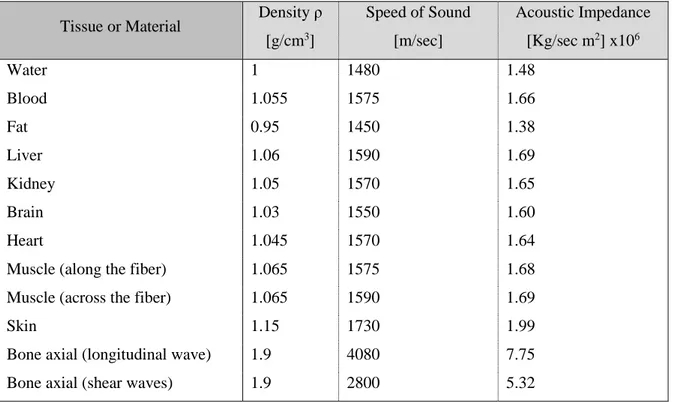
path in a homogeneous medium and it can be absorbed or reflected by the material itself. Different materials respond differently by the passage of ultrasound, depending on the extent to which their medium particles resist to changes due to mechanical disturbance. This property is called characteristic acoustic impedance (Z) and increases in proportion to the density of the material and the velocity of ultrasound in that particular material. The characteristic acoustic impedance, considering a planar wave, may be defined as the product of density and the speed of sound in that material:
𝑍 = 𝜌 𝑐 (1. 18)
The table below shows the typical acoustic properties of some tissue [19]; it is important to underline that in most cases the speed of sound varies with temperature.
Tissue or Material Density ρ [g/cm3] Speed of Sound [m/sec] Acoustic Impedance [Kg/sec m2] x106 Water 1 1480 1.48 Blood 1.055 1575 1.66 Fat 0.95 1450 1.38 Liver 1.06 1590 1.69 Kidney 1.05 1570 1.65 Brain 1.03 1550 1.60 Heart 1.045 1570 1.64
Muscle (along the fiber) 1.065 1575 1.68
Muscle (across the fiber) 1.065 1590 1.69
Skin 1.15 1730 1.99
Bone axial (longitudinal wave) 1.9 4080 7.75
Bone axial (shear waves) 1.9 2800 5.32
Table 1- Acoustic Impedance of some material
When a wave passes form one material to another, or when it encounters discontinuities in the same media, part of its energy is reflected, and part is transmitted with or without changing the direction. In ultrasound application, the wave reflected along a straight line to the source is called echo, while the one that is reflected to other direction are referred as “backscatter”. The portion of material in which the materials show different value of acoustic impedance is called acoustic boundaries, or tissue interfaces. The surfaces hit by the ultrasound wave can be irregular in shape and cause two different type of reflection: specular reflection and non-specular reflection. The first one happens when the ultrasound wave encounters an interface whose boundaries are smooth and larger than the US wavelength, while the non-specular reflection occurs when the dimension of the target is smaller. In this kind of reflection, the particles do not reflect but they vibrate producing spherical wave in all the directions with an
intensity equal to a fraction of the incident beam. In medical image, this phenomenon is responsible of noise and speckle in the US image.
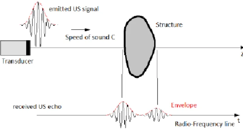
Figure 1. 1 Ultrasound beam [http://www.usra.ca]
The specular reflection follows a law similar to that governing the reflection of light; in particular the angle of reflection (θr) is the same of the angle of incidence (θi), namely the angle between the incident beam and the normal direction to the reflecting surface. Thus, the probability that an echo is detected by the generating transducer, increase as the angle of incidence decreases [15]. Experimental observations have shown that the transmitted wave is deflected according to the transmission angle (θt). The value of this deflection is easily demonstrated in optic and obeys the Snell’s law, which is defined as [19]:
𝑐1
sin (𝜃𝑖)
= 𝑐2 sin (𝜃𝑟)
(1. 19)
Where
c
1 is the wave speed in the tissue 1 andc
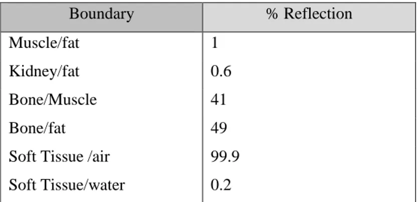
2in the tissue 2, that are correlated with the acoustic impedance. For this reason, it is possible to correlate the intensity of an echo due to specular reflection with the difference in acoustic impedance values of the two media forming the boundary. The ratio between the intensity of reflected echo (Ir) and the intensity of the incident beam (Ii) can be expressed as [19]: 𝐼𝑟 𝐼𝑖 = 𝑍2cos(𝜃𝑖) − 𝑍1cos(𝜃𝑡) 𝑍2cos(𝜃𝑖) + 𝑍1cos(𝜃𝑡) (1. 20) Where Z represents the acoustic impedance of the materials that form the boundary. This ratio is called reflection coefficient and it represents the proportion of the beam intensity that is reflected from the interface; materials with different acoustic impedance show different intensity of the reflected beam that can be detected by the electronic system and used to differentiate material that compose a specific medium. However, the values of Z for soft tissues are quite similar each other, thus attention should befocused not on the absolute value of Z, but rather on the comparison of the values in different materials. Considering the energy reflection for normal incidence, it is possible to gather the values showed in the table below [20]. Boundary % Reflection Muscle/fat 1 Kidney/fat 0.6 Bone/Muscle 41 Bone/fat 49
Soft Tissue /air 99.9
Soft Tissue/water 0.2
Table 2 Energy ultrasound reflection in some human boundaries
Ultrasound Attenuation
Experimental observations have showed that the amplitude of a planar acoustic waves propagating in a homogeneous medium decrease with the wave travelling distance. This energy loss depends on reflection, scattering, refraction and absorption. The latter refers to the process by which the energy is transformed into a different form of energy, mostly heat. The extent of absorption in media is mainly affected by three factors: viscosity, relaxation time of the medium and beam frequency [20]. In particular, absorption increases with viscosity. The relaxation time is a measure of time taken by particles to revert to their mean positions after a solicitation. When the relaxation time is long, the vibrating particles do not return to their original position before the next disturbing pulse, resulting in dissipation energy due to collision of waves moving in opposite direction. Thus, a long relaxation time of medium causes a high value of absorption. In line of what just described, the absorption of ultrasound increases with the increasing beam frequency because the particles do not have time to revert to their original position if the frequency of the pulses is too high. The reduction of amplitude versus distance of a planar acoustic wave is called ultrasound attenuation, and in nature is exponential. Thus, can be described as:
𝑃(𝑥) = 𝑃0𝑒−𝛼𝑥 (1. 21)
where P0 is the wave pressure at some reference point, and α is the attenuation coefficient characteristic of each material. Respect to the intensity, the formula can be written as:
𝐼(𝑥) = 𝐼0𝑒−2𝛼𝑥 (1. 22)
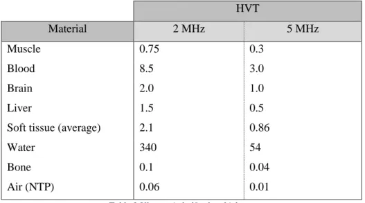
The attenuation coefficient depends also on the frequency of the wave. In medical imaging, the attenuation of a specific medium may be quantified in terms of ultrasonic half value thickness (HVT), that correspond to the distance in that medium in which the intensity of the beam reduces to one half its
original value. The table below illustrates the value of ultrasonic HVT in different materials with a frequency of the beam of 2 MHz and 5 MHz [20]:
HVT Material 2 MHz 5 MHz Muscle 0.75 0.3 Blood 8.5 3.0 Brain 2.0 1.0 Liver 1.5 0.5
Soft tissue (average) 2.1 0.86
Water 340 54
Bone 0.1 0.04
Air (NTP) 0.06 0.01
Table 3 Ultrasonic half value thickness
Table 3 shows that the HVT value for water, and similarly for other liquid, is higher than the other materials. This means that the ultrasound waves can travel long distance in liquids without attenuate their intensity. The main reason of this phenomena is that liquids are acoustically homogeneous and there are no acoustic boundaries within them.
1.2.2 Ultrasound image formation
As described above, ultrasound waves are produced by a piezoelectrical transducer. When a wave encounters an acoustic boundary, some of the ultrasound energy is reflected and interacts with the original piezoelectric crystal. It, converting the energy in electric potential, generates a signal that is electronically processed and measured in order to detect the location of the boundary within the tissue. The set of signals produced along one beam path is referred as a scan line. The ultrasound image is built by collecting a number of scan lines equal to the number of transducers that make up the ultrasound probe. The signals generated by the returning echoes are firstly amplified to increase their intensity. Moreover, in order to reduce the effect of acoustic attenuation in the media, they are subjected to a time gain compensation (TGC). This process applies different amplification to signal received from different tissue depth: echoes originating from longer distance are more amplified that those from short distances. There are many ways to visualize the signal and it depends on the characteristic of the probe, the scope and the physical properties of the tissue to be imaged.
The simplest way of visualization is A-Mode, Amplitude Mode. It consists of displaying the amplitude of 1D echoes of a single pulse, as a function of the distance it has traveled in the direction of propagation. The signal echoes are transformed in the form of spikes by a cathode ray oscilloscope (CRO). Thus, the
position of a spike in time is associated to a measure of distance between the position of the reflecting boundary and the transducer.
Figure 1. 2 A- Mode visualization [18
The B-Mode, brightness mode, is the display of 2D map composed by dots of varying intensities, corresponding to the echo intensity evaluated with the same modality of the A-Mode. The z-axis of the image correspond to the distance of the boundaries and the brightness of each dots is correlated with the intensity of the echo generated in that specific position. The B-mode is used for real-time imaging: numerous images are generated repetitively at a rate exceeding about 25 frames per second to create the impression of continuity in time. This modality is the most used in medical application, and in particular for assisted breast biopsy because allows the simultaneously visualization of the lesion and the needle insertion. Other visualization modalities are M-Mode, a time motion display of a chosen ultrasound line, and the Doppler mode that make use of the Doppler effect to measure and visualize fluids flow.
1.2.3 Ultrasound resolution
Spatial resolution
Spatial resolution represents the ability of the Ultrasound system to distinguish two structures close to each other. It depends on the contribute of the medium and at the same time on the frequency characteristic of the ultrasound transducer.
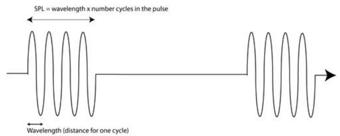
Figure 1. 3 Series of ultrasound pulses https://sites.google.com/site/ektasphysicseportfolio/spatial-pulse-length
It is defined as the product of the number of cycles in a pulse of ultrasound and the wavelength: 𝑆𝑃𝐿 = #𝑐𝑦𝑐𝑙𝑒𝑠 𝑖𝑛 𝑝𝑢𝑙𝑠𝑒 𝑋 𝑤𝑎𝑣𝑒𝑙𝑒𝑛𝑔𝑡ℎ (𝑚𝑚) (1. 23)
Most pulses consist of two or three cycles, the number of which is determined by the damping rate of the piezoelectric elements of the ultrasound transducer [24].
Axial resolution, also called longitudinal resolution, is the minimum distance that can be differentiated
between two elements located parallel to the direction of the ultrasound beam. Mathematically, it is equal to half the spatial pulse length.
𝐿𝑜𝑛𝑔𝑖𝑡𝑢𝑑𝑖𝑛𝑎𝑙 𝑅𝑒𝑠𝑜𝑙𝑢𝑡𝑖𝑜𝑛 = 𝑆𝑃𝐿
2 (1. 24)
For the piezoelectric nature of the transducer, the wavelength of the ultrasound beam is equal to twice the thickness of the element in the transducer. Having a good longitudinal resolution means that the damping rate of the ultrasound transducer is high. However, an excessive damping is associated with loss of amplitude and hence to a low-intensity ultrasound beam. Moreover, soft tissue attenuates high-frequency pulses, which means that wave with high high-frequency are not able to be reflected back with a detectable intensity by deep boundaries [24].
Lateral resolution is the minimum distance that can be distinguished between two targets located
perpendicular to the direction of ultrasound beam. It is strictly correlated with the beam width that varies with the distance of the transducer. The beam width at the beginning is approximately equal to the width of the transducer, then converges to its narrowest width, equal to half of the width of the transducer, at a distance called the near-zone length. At a distance greater than this zone, the beam diverges such it
becomes the width of the transducer at a distance twice than the near-zone length [24]. So, lateral resolution is determined by the equation:
𝑁𝑒𝑎𝑟 𝑧𝑜𝑛𝑒 𝑙𝑒𝑛𝑔ℎ𝑡 = 𝐴𝑟𝑒𝑎 𝑜𝑓 𝑡𝑟𝑎𝑛𝑠𝑑𝑢𝑐𝑒𝑟
2
4 ∗ 𝑤𝑎𝑣𝑒𝑙𝑒𝑛𝑔ℎ𝑡
(1. 25)
Thus, it can be implemented using focusing techniques, that create focal region within the near zone, reducing the near-zone length to a shorter value called focal length. It permits to have an optimal resolution in the region of interest and to increment the lateral resolution in that zone.
Contrast resolution
Contrast resolution refers to the ability to distinguish between different echo amplitudes of adjacent structures. It may be enhanced at various stages in the image processing, including compression of the dynamic range, image memory and use of contrast agents. The ultrasound image is made by pixels. The visualization of various shades of grey depends on the number of bits of each pixel, that has to be the highest possible. For example, a 5-bit memory enables 32 shades of gray to be stored [24], and thus to have a higher contrast resolution and a better quality of the image.
1.2.4 Artifacts of ultrasound image
Ultrasound artefacts can be grouped in different ways depending on the ultrasound modality, such as B-Mode or Dobbler mode, but also on the type of assumptions that they violate, such those related to the internal structure of the ultrasound transducer, or those that are primarily related to beam properties and processing. In short, the principal assumptions used in ultrasound evaluation are that pulses and echoes travel along a straight path, echoes return to the transducer after a single reflection and travel at a uniform speed of 1540 m/s and that the attenuation is uniform by all the tissues [27].
The reverberation artifact violates the assumption that an echo returns to the transducer after one reflection, and it is usually caused by significant differences in the acoustic impedance of two adjacent tissues [26]. A portion of a reflected echoes encounters another reflector and it reflect a second time before going back to the transducer. This is interpreted by the system as a boundary that is further away than the original structure. The comet tail artifact is caused by multiple reverberation from multiple closely refractors.
Similarly, in the mirror image artifacts the ultrasound wave is initially reflected from the original object and then encounters a highly reflective structure that reflects again the wave that hits for a second time the initial object with a different incident angle. This phenomenon causes two different echoes of the same object that is displayed twice equidistant and on the opposite side of the reflector, creating a mirror image. Luckily these artefacts are usually easy to detect because they are very recognizable.
Acoustic shadowing violates the assumption that echoes are attenuated equally by all the tissues.
Indeed, this artefact is caused by a partial or complete attenuation of the ultrasound beam along its path in a specific media, which is responsible of a loss of signal and a consequent shadowing of the image. A very common problem is the shadowing caused by air that forms an impenetrable barrier to sound causing a very poor-quality image. The enhancement artifact is caused by a material that has an attenuation coefficient higher than the one assumed and produces a too bright image with a consequently reduction of the quality.
The speckle artifact is determined by the interference of objects that are too small to be detected by the ultrasound beam. The resulting image appears noisy and characterized by a granular texture. Modification of spatial resolution and frequency may help to reduce this artifact.
Refraction artifact follows the physical law of refraction that assumes that when a beam encounters a
tissue interface it changes its direction according to the tissue refractive index. This entails that objects that are not truly in the scanned field of view can be artifactually represented on display, causing object position misregistration, duplication or lateral defocusing of curved edge [26]. These artifacts are easily recognizable because show in the image anatomically impossible structure and can be eliminated by changing the angle and the position of the transducer.
Beam width artifact violates the assumption that echoes are generated only by one reflector. It occurs
when an object is located after the beam focal zone and creates false detectable echoes that are displayed as overlapping the structure of interest.
The range ambiguity artifact is since an error of pulse assignation can be made when pulses of high frequency are used. In particular, the information related to the echo of one pulse can be wrongly associated to the following or previous pulse. In order to reduce this artifacts, it is possible to reduce the pulse repetition frequency.
The speed error artifact occurs when the assumption of the fixed velocity of sound in tissue is violated. For example, ultrasound wave travels fatty tissue with a velocity lower than 1540 m/s and in this media shallow objects may be misrepresented in the image as deeper.
To reduce the effect of these artifacts is possible to change the orientation of the US probe, the pulse frequency of the transducer or to use post-processing image techniques in order to improve the image quality and clarity.
1.2.5 Acoustical properties of some polymers
One of the peculiar properties that the pressure sensor to design must have is the acoustically transparence. It means that the ultrasound wave does not have to be attenuated by the material itself, and
the intensity of the reflected wave at their boundaries must be as lower as possible in order to have a high-intensity wave in the soft tissue to analyze. The pressure sensor is in contact with the human skin; having a low-intensity reflected wave means to have a material with an acoustically impedance close to the acoustic impedance of the skin. In literature there are several studies in which the optoacoustic properties of different materials have been studying to develop phantoms able to mimic soft tissue optical and acoustic properties. The development of these phantoms is an important tool for testing and optimization of medical ultrasound system for medical training [30]. Studies have shown that materials that mimic efficiently soft tissue are hydrogels, a group of polymeric material with a hydrophilic functional group attached that is able to absorb a great amount of water. Because they are mainly consisting of water, they have low acoustic attenuation and an impedance coefficient and a speed of sound similar to biological tissue. The most common hydrogel materials are polyvinyl alcohol gel (PVA), polyacrylamide gel (PAA), gelatin and agar [30]. They show very good acoustic properties and an acceptable stability over time. Another very common material is Polyvinyl Chloride-Plastisol (PVCP), a white opaque solution of monomers that polymerizes in a non-toxic plastic and it’s insoluble in water. Plastisol changes its structure when heated around 200˚C becoming transparent. It is usually mixed with other particles to acquire better mechanical properties or to obtain specific optic properties that better mimic the behavior of soft tissues [28,29]. This material is very easy to manufacture in several different geometry with an acceptable structure rigidity; it shows chemical and elastic stability and for these reasons it is used for tissue mimicking. Cafarelli et al. [30] have studied the acoustical properties of polydimetrhylsiloxane (PDMS), a silicon-based organic polymer widely used in microelectromechanical systems. It shows an acoustic impedance value slightly higher than PAA, and an attenuation coefficient significantly higher. However, the latter value increase with the material concentration and quantity of material exposed to sound wave. Thus, the effect of interposing a soft sensor constituted of PDMS between the skin and the ultrasound transducer is unknow, and it is hard to suppose this effect using the only knowledges of the acoustic properties of the materials that compose it.
2. TACTILE PRESSURE SENSOR
Women breast is characterized by several type of tissues; in particular they are made up lobules and ducts necessary to the production and transportation of milk, covered by fibrous and fat tissues that give the breast size and shape. The composition can change during lifetime and is peculiar for each woman. Tissues differentiation capability is one of the main goals to aim in the design of the pressure sensor. Commercially medical devices able to asses elastographic data are described in the chapter 1.1. One example is the SureTouch system that exploits the mechanical elastography method.
Figure 2. 1 SureTouch [37]
It is an FDA-cleared medical device that provides a painless breast exam with the use of an array of tactile sensor mounted on a handheld probe. As the probe is pressed against the breast, the sensor array captures varying reaction pressures caused by differences in tissue hardness. The probe head measures 50 x 40 mm with a curvature radius of 38 mm, and it is made of 192 pressure sensors arranged in an array (16 x 12) that covers a surface of 40 x 30 mm [37]. Each pressure sensor has a rectangular pressure sensing area of 2.5 x 2.5 mm with a sensitivity of about 0.05 kPa [12]. SureTouch provides a 3D image of the breast with a quantitative evaluation of relevant lesion features, such as size, shape, hardness, heterogeneity, and mobility. Therefore, mechanical elastography, simulating manual palpation, aims to reconstruct the composition of a volume of tissue from surface mechanical measurements. The same problem is debated and studied in Robotics, where it is necessary to have a system able to create a map
of the environment in which the robot has to operate. While optical vision can recognize the surface of a material, the sense of touch is able to identify material texture and composition. This property replicates exactly the human sense of touch and it is usually made by a tactile sensing system, that consist of flexible touch sensing arrays, access electronics and algorithms for data sampling and processing. It plays a fundamental role in the manipulator control system since it can estimates contact parameters between the robot and the environment such as contact force, slip, hardness and texture. These functions are important constituent for the manipulator safe interactions and permit to resolve object recognition and grasping problems and to characterize different materials by their mechanical properties. Soft tactile sensors are realized via a variety of electronic structures and materials; the most common are made by piezoresistive composite or liquid metal conductors embedded in a polymer material, such as PDMS or other photocurable rubbers.
The main idea is to use a capacitive tactile sensor that is able to mimic the SureTouch ability of tissue differentiation and to implement the control loop of the robot. Mechanical imaging techniques based on soft sensor could facilitate imaging of sensitive, curved, hard or heterogeneous tissues and could capture quantitative data during existing clinical physical examination practices [14]. According with the current method used for mechanical elastography, an array of soft capacitive tactile sensors can provide the same tissue mechanical information gathered by the SureTouch medical device. In this chapter, some characteristics of two soft capacitive tactile sensors are evaluated and compared with the performance of SureTouch. However, there is no studies that estimate the interaction of ultrasound waves with the components of tactile sensor; thus, the primary constrain of acoustically transparence cannot be evaluated and it is not possible to consider the usage of tactile sensors as a real solution for the MURAB project.
2.1 Capacitive soft sensors
The sensing modality of the capacitive tactile sensors considered in this evaluation, uses variation of electric charge between two stimulated plates to describe the pressure distribution above their surfaces. For a parallel plate configuration, the easiest expression of capacitance is:
𝐶 = 𝜀0𝜀𝑟 𝐴
𝑑 (2. 1)
where A is the overlapping area of the plates, d is the distance between the plates and ε0 and εr represent respectively the permittivity of vacuum and the dielectric constant of the material between the two plates. While the numerator of the expression is fixed by the geometrical constrains of the sensor, the variation of the d value results in a change of capacitance. If the plates are connected to an electrical
circuit, the capacitance can be expressed as the ratio of the charges on the plates (q), and the voltage between the plates (V).
𝐶 =𝑞
𝑉 (2. 2)
This value can be detected by an electronic circuit and it is strictly correlated with the distance variation of the two plates. Thus, the application of forces to the sensor plates cause a different relative position of plates and consequently a capacitance variation that is detected by the electronic circuit.
The capacitive soft sensors considered are made of two layers of conductive channels in a substrate of a stretchable polymer. The one proposed by Shanshan [39], is made of highly conductive silver nanowires (AgNW) patterned by screen printing in a Silica substrate and transferred to a PDMS layer. Two layers of PMDS – AgNW composite are positioned orthogonally and laminated together with an Ecoflex film. Instead, Bin Li et all [38] propose a sensor made of two groups of microchannels filled with eGaIn and embedded on separate planes with orthogonal orientation in a silicone polymer substrate. A picture of this sensor is represented in the Figure 2.2.
Figure 2. 2 Capacitive Tactile sensing [38]
As the structure of these two sensors is more complex of the case of two conductive plates, the expression of the capacitance expressed before cannot be used. However, it is possible to define a model for electrical capacitance between a pair of orthogonally conductive microchannel, by combining the electrostatic method of images, the superposition principle, and elements of transmission line coupling theory [38]. The models used in both sensors are described in the relative papers.
2.2 Sensor Performance
Sensor performance describes several instrumentation testing, diagnostic and analysis techniques to verify the reliability, health and performance of a sensor process. Static accuracy describes how closely the sensor signal represent the actual measured being monitored, after the transient period. The static calibration curve, also known as transfer function, plots the output amplitude vs different inputs and visually shows some characteristic of the sensor as:
- Sensitivity is a measure of output change relative to a unit change in the input. It represents the slope of the transfer function.
- Resolution is the minimum detectable input signal.
- Range is the sensible range of input and output of the sensor.
- Linearity describes how well a straight line approximates the calibration curve over the specific range. The nonlinearity error corresponds to the maximum deviation of the actual measured value from a linear transfer function.
- Drift is the deviation from a specific reading of the sensor when the sensor is kept at that value for a prolonged period.
- Precision is the capacity of a measuring instrument to give the same reading when repetitively measuring the same quantities under the same prescribed conditions. This term is closely related to repeatability, that is the precision of a set of measurements taken over a short time interval, and reproducibility that consider a set of measurement taken over a long-time interval and performed by different operator with different instruments and in different laboratories.
- Over force is the maximum force which safely may be applied to the sensor.
- Hysteresis is the dependence of the system on its history and represents the difference in output when any value of the measurand is approached from the low and the high side. - Dynamic characteristics represent the time response of the sensor system and include rise
time, delay time, peak time, setting time. The dynamic linearity is a measure of the sensor ability to follow rapid changes in the input parameters.
Moreover, two other characteristics are important to determinate the sensor quality. One of these is
lifetime, which represent the effective time in which the sensor remains sensitive and functional under
normal operating conditions, and temperature range that is the range over which the sensor produces an output proportional only to the force.
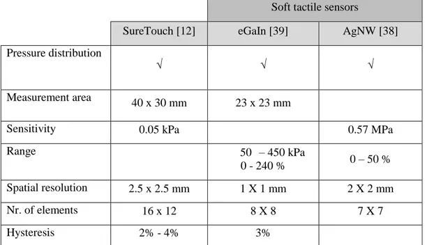
In order to verify if the two conductive tactile sensors previously described have the same capability of the SureTouch system, some information about sensor performance are gathered and reported in the table 4.
Soft tactile sensors
SureTouch [12] eGaIn [39] AgNW [38]
Pressure distribution
√ √ √
Measurement area 40 x 30 mm 23 x 23 mm
Sensitivity 0.05 kPa 0.57 MPa
Range 50 – 450 kPa
0 - 240 % 0 – 50 %
Spatial resolution 2.5 x 2.5 mm 1 X 1 mm 2 X 2 mm
Nr. of elements 16 x 12 8 X 8 7 X 7
Hysteresis 2% - 4% 3%
Table 4 Comparison of some SureTouch and tactile sensors characteristics
It is evident that the soft tactile sensor evaluated are less performing that the capacitive sensors used in the SureTouch medical device. It is demonstrated that the sensitivity of sensors made of carbon nanotube electrodes shows a sensitivity of 0.23 MPa over the pressure range up to 1 MPa, and those with serpentine gold electrodes a sensitivity of 0.48 MPa [38]. However, Bin Li et All [14] have verify that the sensor made of soft polymers and microfluidic electrodes, described in the section above, has the capability to perform mechanical elastographic measurements. The tactile sensor described is integrated to a circuit for capacitance measurement (AD7746, Analog Device) and is able to robustly image lumps in soft tissues [14]. Soft tactile sensors are gathering increasing attention in the scientific world, and a great number of research groups are developing new fabrication machines able to print customizable electronic circuit over a polymer substrate. Thus, there is reasons to believe that the use of soft tactile sensors for elastographic measurements, will be a commercially solution in the next future.
3. ULTRASOUND PRESSURE SENSOR
The idea promoted by the University of Twente is to use a pad of an acoustically transparent material and the ultrasound imaging to detect the pressure on its surface. While the mechanical model and the sensing modality of this type of sensor are described in the first section of this chapter, the second section summaries some considerations about the design of the sensor and some possible implementations.
3.1 Sensing modality
The sensor is a rectangular shape pad made of a controlled percentage of Plastisol and plasticizer that contribute to vary the stiffness of the material. It is designed to fit over the US probe, and it is fabricated by a molding process.
Figure 3. 1 Ultrasound pressure sensor concept [40]
The first assumption is to consider the pad made of a material that returns to its original shape when the loads are removed following a linear elastic model. Assuming that the total strain is small, the relation between the strain and the stress is defined by the Young’s modulus
(E)
of the material. For simplicity, the stress applied is considered normal to the material surface with a consistent strain only in one direction. Thus, stress and strain relation can be simplified in this form:𝜎𝑧𝑧= 𝐸 · 𝜀𝑧𝑧 (3. 1)
where
σ
zzdefines the normal stress applied along the z-axis, and theε
zzthe strain associated. The strain is a measure of deformation representing the ratio between the displacement(Δl
z)
between two point of the material and a reference length that is usually the absolute length(L
z)
of the material considered. Mathematically, can be expressed as:𝜀𝑧𝑧 =
𝛥𝑙𝑧
𝐿𝑧
The displacement of the material after the application of a normal force, can be sensed with different methods and technology and permits to calculate the relative stress and thus the overall force applied to the material. 𝜎𝑧𝑧= 𝐹 𝐴= 𝐸 · 𝛥𝑙𝑧 𝐿𝑧 (3. 3) The main idea of this type of sensor is that the displacement is measured thanks to the evaluation of ultrasound images. The figure below shows the US image of a phantom made of two different materials (M1, M2). The phantom is pressed by a transducer covered with a 3 mm thick pad sensor. Boundaries between different materials are visible, and it’s possible define three different regions: the upper one represents the pad itself, the middle and the lower part are characterized by the different materials of the phantom.
The sensing modality is defined by measuring the thickness of the material, using the images gathered from the US detection, under unknown pressures. The idea is to have a pad made of a material completely characterized and of which the elastic modulus is known. The value of the displacement, the initial length of the pad and the Young’s modulus, permit to obtain the overall stress applied to the phantom. This value can be correlated with the displacement of the other materials and associated with an elastic modulus. The measurements from the US images are processed manually; the thickness of the pad is measured by counting the pixels at different spots on the boundaries and averaging them. The
measurement area of the pad is the same of the active surface of the ultrasound probe used, around 50 mm2. Since the ultrasound transducer has to scan the entire surface of a breast without causing pain to the patient, the sensor has to be sensible to small forces, up to a maximum value of 20 N.
3.2 Sensor considerations
According to the works made previously by the RaM group at the University of Twente, the pad has to fit well onto the probe and has to have an area equal to the surface of the transducer. To fulfill this requirement, a complex mold is used, showed in the figure 3.3.
Figure 3. 3 Mold for manufacturing the ultrasound pressure sensor [40]
A model of the ultrasound probe used for the experiment is designed and 3D printed. It is used as a part of the mold, that consists in a lower part with dimensions slightly bigger than the ultrasound probe and an external structure able to hold the 3D printed ultrasound probe and change its position. The Plastisol mixture is poured into the lower part of the mold and solidifies in the specific shape showed in figure 3.1. With this type of mold, it is possible to varying the thickness of pad, and consequently the range of measurements detectable. In particular, considering an application force of 10 N and supposing the pad made of a material with an elastic modulus E equal to 50 KPa, the theoretic strain percentage is:
𝜀 = 𝐹
𝐴 · 𝐸 = 4 % (3. 4)
This means that if the pad has an initial length of 1 mm, the displacement is equal to 0.04 mm. This value is too much low and the ultrasound image is not able to detect any depth variation. Thus, the ultrasound pressure sensor described, can work only if the initial depth of the sensing area is long enough to show a displacement that can be detected by the ultrasound images that, as described in Chapter 1.2, have a specific resolution and are affected by image artifacts. Therefore, the correct approach for improving this type of sensor is firstly to evaluate which is the minimum pad depth necessary to use the
ultrasound imaging as sensor technology. However, this value is strongly correlated with the composition of the pad and the mechanical elasticity that it exhibits.
So, the approach to follow for the ultrasound pressure implementation can be summarized in:
1. Study the best material composition for the Ultrasound Pressure sensor. It has to be acoustically transparent and strong enough to be fitted in the ultrasound probe.
2. Study the mechanical compression behavior of the new material and evaluate its elastic modulus. To do this evaluation, it is necessary to have a material tester with a simple geometry that can be easily reproduced. An example of tester material is reported in Chapter 4.
3. Once the material is fixed, evaluate tester pads with different depth length, with the ultrasound imaging.
4. Compare the results, such as image quality, sensor linearity and sensor range, to study the pad depth that best fit this problem.
5. Manufacture the ultrasound pressor sensor with the desired shape using the mold of figure 3.3. 6. Test the capability of tissue differentiation.
In this thesis, a tester material is produced and a method for determining the sensor sensitivity is proposed.
![Figure 1. 1 Ultrasound beam [http://www.usra.ca]](https://thumb-eu.123doks.com/thumbv2/123dokorg/7392443.97246/18.892.247.639.213.501/figure-ultrasound-beam-http-www-usra-ca.webp)
![Figure 2. 1 SureTouch [37]](https://thumb-eu.123doks.com/thumbv2/123dokorg/7392443.97246/26.892.240.650.442.766/figure-suretouch.webp)
![Figure 2. 2 Capacitive Tactile sensing [38]](https://thumb-eu.123doks.com/thumbv2/123dokorg/7392443.97246/28.892.202.686.600.795/figure-capacitive-tactile-sensing.webp)
![Figure 3. 1 Ultrasound pressure sensor concept [40]](https://thumb-eu.123doks.com/thumbv2/123dokorg/7392443.97246/31.892.111.776.540.673/figure-ultrasound-pressure-sensor-concept.webp)
