Effect of some inhibitors on the passivation of galvanized rebars
embedded in concrete
Curriculum: Materials Engineering
Ph.D. Dissertation of:
Daria Timofeeva
Supervisors:
Dr. Tiziano Bellezze Prof. Gabriella Roventi
Coordinator:
Prof. Ferruccio Mandorli
Daria Timofeeva
Effect of some inhibitors on the passivation of galvanized rebars embedded in concrete
Doctoral School on Industrial Engineering i
Acknowledgements
I wish to express my sincere appreciation to those who have contributed to this thesis and supported me in one way or the other during this amazing journey.
First of all, I am extremely grateful to my supervisors, Dr. Tiziano Bellezze and Prof.
Gabriella Roventi, for always giving necessary suggestions to perform this study. In spite of the encountered difficulties, they guided me to the goal and now it is finally achieved.
My sincere gratitude is reserved for Professor Romeo Fratesi for his advice and providing numerous sources of information on corrosion and protection of materials. It has always been friendly upbeat working atmosphere in the team due to him. His cheerful disposition is legendary among students and colleagues, and no corrosion conference is complete with-out someone remember an interesting phrase once said by him.
I would also like to take this opportunity to thank Dr. Giampaolo Giuliani for invaluable technical assistance. I owe him every single piece of steel galvanized and every single hole drilled in the sample. He is the most indispensable man in the laboratory.
Very special thanks to Dr. Sergey Saltykov, the Head of the Department of Chemistry at the Lipetsk State Technical University, for his commitment and devotion to science that inspire students to follow his footsteps.
Heartfelt thanks to all my friends whom I was lucky enough to have met in Italy, in par-ticular to Evgenia, Emanuele, Inna, Katarina and Anna. They have always come to my rescue in any time I needed, helping me by word and deed. I am very grateful for all the care they have taken of me.
Finally, I would like to acknowledge my parents for all the attention and love, they gave me and for the trust, they always had in me. I would not be here if it not for them. They are the most important people in my world and I dedicate this thesis to them.
Daria Timofeeva
Effect of some inhibitors on the passivation of galvanized rebars embedded in concrete
Doctoral School on Industrial Engineering iii
Abstract
The use of hot-dip galvanized steel reinforcements is one of the most common methods used to prevent deterioration of reinforced concrete structures. Zinc active corrosion, which occurs just after the embedding of galvanized steel in concrete, is accompanied by gaseous hydrogen evolution, which causes the loss of adhesion between the zinc coating and the cement paste still not hardened.
Chromium VI compounds are strong oxidants naturally present in the cements andreduce the passivation time and the amount of hydrogen developed. The EU Directive 2003/53/EC obliges to keep the content of soluble chromium VI in cement below 2 ppm on the total dry weight of the cement due to its toxicity and carcinogenic properties.
The objectives of this research project were to find a replacement for chromium VI com-pounds through study of galvanized steel passivation mechanism in concrete in presence of chromates and comparison of several inhibitors by their effectiveness as on zinc corrosion. The oxygen effect on the process of zinc passivation was also studied. The investigation was performed both in concrete and in saturated solution of calcium hydroxide, by means of corrosion potential and impedance measurements. To study the changes in the passivating layer, scanning electron microscopy, energy-dispersive X-ray spectroscopy and X-ray diffrac-tion analysis were utilized.
The results obtained indicate that the passivation of galvanized steel in concrete containing chromates occurs in several steps with different mechanisms and that dissolved oxygen plays an important role on the beginning of the passivation process. Among inhibitors studied in present work, nitrite seems to be the most promising, both in concrete and in Ca(OH)2
sat-urated solution. The future development of this research could be a depth study of the nitrite impact and a further search for alternative environmentally friendly corrosion inhibitors of galvanized steel.
Daria Timofeeva
Effect of some inhibitors on the passivation of galvanized rebars embedded in concrete
Doctoral School on Industrial Engineering v
Riassunto
L’uso di barre d’acciaio zincate a caldo è uno dei metodi più comuni per prevenire il deterioramento delle strutture in calcestruzzo armato. La corrosione attiva dello zinco, che avviene subito dopo l’immersione dell’acciaio galvanizzato nel calcestruzzo, è accompagnata dallo sviluppo di idrogeno, che causa la perdita di adesione tra il rivestimento di zinco e la pasta di cemento non ancora indurita.
I composti di cromo VI sono forti ossidanti naturalmente presenti nei cementi che riducono il tempo della passivazione e la quantità d’idrogeno sviluppato. La Direttiva 2003/53/ CE obbliga a mantenere il contenuto di cromo VI idrosolubile nel cemento al di sotto di 2 ppm sul peso totale a secco del cemento.
Gli obiettivi di questo lavoro sono stati: trovare un sostituto per i composti di cromo VI attraverso lo studio del meccanismo di passivazione dell'acciaio zincato nel calcestruzzo in presenza di cromo VI e confrontare diversi inibitori per la loro efficacia sulla corrosione dello zinco. E’ stato inoltre studiato l'effetto dell’ossigeno sulla passivazione dello zinco. L'indagine è stata effettuata nel calcestruzzo e in soluzione satura di idrossido di calcio, mediante misure del potenziale di corrosione e prove di impedenza. Per studiare gli strati di passivazione sono state utilizzate la microscopia SEM-EDX e la diffrattometria a raggi X.
I risultati ottenuti indicano che la passivazione dell’acciaio zincato nel calcestruzzo in presenza di cromati avviene in più fasi con meccanismi diversi e che la presenza di ossigeno disciolto è importante per accelerare la passivazione. Tra gli inibitori studiati, il nitrito sembra quello più promettente, sia nel calcestruzzo che in soluzione satura di idrossido di calcio. Gli sviluppi futuri di questa ricerca potrebbero essere l’approfondimento dello studio dell'effetto dei nitriti e l'ulteriore ricerca di inibitori di corrosione a basso impatto ambientale.
Daria Timofeeva
Effect of some inhibitors on the passivation of galvanized rebars embedded in concrete
Doctoral School on Industrial Engineering vii
List of Figures
Figure 2-1. The expansion of corroding steel, causing formation of cracks, delamination,
and spalling. ... 18
Figure 2-2. Scheme of the corrosion of reinforcing steel bar in concrete ... 19
Figure 2-3. Pourbaix diagram for iron at ionic concentrations of 1.0 mM ... 22
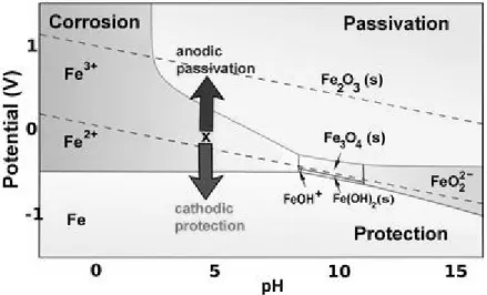
Figure 2-4. Pourbaix diagram for iron: areas of corrosion, passivation and protection ... 24
Figure 2-5. Pourbaix diagram for zinc at 25º C ... 25
Figure 3-1. Microstructure of galvanized coating on steel (200 x) [1] ... 30
Figure 5-1. Concrete mix components: a – WOPC, b – OPC, c – sand, d – medium aggregate ... 43
Figure 5-2. Concrete specimens produced from white (a) and grey (b) cement, withdrawn from molds ... 44
Figure 5-3. SEM image of cross-sectional area of the hot-dip galvanized coating on the steel bar ... 45
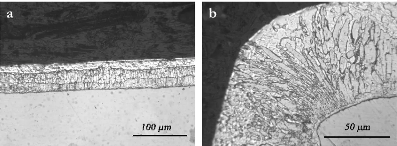
Figure 5-4. Microstructure of the galvanized coating on the steel sheet: working surface, original magnification x 20 (a) and corner protection, original magnification x 50 (b) ... 45
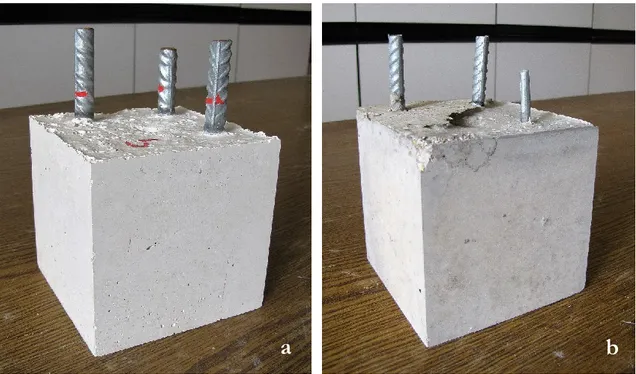
Figure 5-5. Steel bar samples: before (a) and after (b) galvanization ... 45
Figure 5-6. Potential monitoring of galvanized steel samples embedded in concrete by means of Agilent acquisition system ... 48
Figure 6-1. Pure zinc (a) and galvanized steel (b) samples for tests in solution ... 49
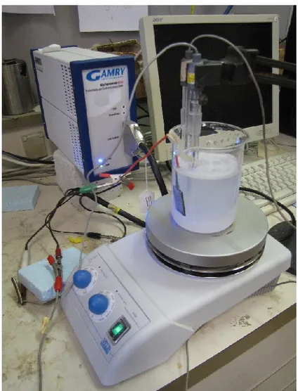
Figure 6-2. Three-electrode electrochemical cell used for the EIS measurements ... 52
Figure 7-1. Corrosion potential change in time of galvanized bars embedded in concrete specimens manufactured with the following types of cement: a) OPC, b) OPC with FeSO4 admixture, c) WOPC ... 54
Figure 7-2. X-ray patterns of the galvanized steel surface after 24 hours of immersion in grey concrete with reduced Cr VI ... 55
Figure 7-3. SEM image of the galvanized steel surface after 24 hours of immersion in grey concrete with reduced Cr VI ... 55
Figure 7-4. Potential change in time of bars embedded in concrete specimens, made with cements containing 0 ppm (a), 3 ppm (b) and 6 ppm (c) Cr VI ... 57
Figure 7-5. Potential change in time of bars embedded in concrete specimens made with cements containing 9 ppm (a), 12 ppm (b) and 15 ppm (c) Cr VI ... 58
Figure 7-6. Potential change in time of galvanized steel sheets embedded in concrete specimens, manufactured with cement containing 15 ppm Cr VI, with indication of time points, when sheets were removed for SEM and EDX analysis: specimen I – after 3 h, specimen II– after 12 h and specimen III – after 25 h of embedding... 59
Figure 7-7. SEM images of galvanized steel sheets surface after the immersion in concrete made with cement containing 15 ppm Cr VI for: 3 h (a), 12 h (b) and 25 h (c) ... 60
Figure 7-8. X-ray patterns of galvanized steel sheets after the immersion in concrete specimens made with cement containing 15 ppm Cr VI for: 3 h (a), 12 h (b) and 25 h (c) ... 61
Figure 7-9. EDX analysis performed on zones of galvanized steel sheets marked in Figure 8: a) 3h, b) 12 h and c) 25 hours of immersion ... 62
Figure 7-10. Corrosion potential change in time of pure zinc sample immersed in Ca(OH)2 saturated solution with additions of 0.05M K2Cr2O7 solution ... 63
Figure 7-11. Corrosion potential change in time of pure zinc sample immersed in Ca(OH)2 saturated solution with one-time addition of chromate ... 64
Figure 7-12. SEM image of zinc sample surface after 20 hours of immersion in Ca(OH)2
saturated solution with addition of 6.07 ppm Cr VI ... 64 Figure 7-13. EDX patterns of zinc sample after 20 h the immersion in Ca(OH)2 saturated
solution with addition of 6.07 ppm Cr VI... 65 Figure 7-14. Corrosion potential of pure zinc samples in Ca(OH)2 saturated solution
containing different Cr VI concentrations ... 66 Figure 7-15. Corrosion potentials of galvanized steel sheet in Ca(OH)2 saturated solution
containing the Cr VI concentrations indicated by the dotted line ... 66 Figure 7-16. Nyquist plots of galvanized steel sheet in Ca(OH)2 saturated solution with
changing Cr VI concentration ... 67 Figure 7-17. Change of polarization resistance in time for pure zinc samples immersed in Ca(OH)2 saturated solutions without addition of Cr VI (♦) and with different Cr VI
concentrations: ■ – 1.6 ppm, □ – 2.3 ppm, ▲ – 3.1 ppm, Δ – 6.2 ppm ... 68 Figure 7-18. Microscope observation of pure zinc sample after 24 hours of immersion in Ca(OH)2 saturated solution with 6.2 ppm Cr VI, original magnification x 100 ... 68
Figure 7-19. Potential change in time of zinc sample in deaerated Ca(OH)2 saturated
solution ... 69 Figure 7-20. Potential change in time of galvanized steel sample with progressive deaeration of Ca(OH)2 saturated solution ... 69
Figure 7-21. Open circuit potential change in time of galvanized steel sheets immersed
in Ca(OH)2 saturated solution without inhibitors and with addition of inhibitors:
3 wt% NO2-, 0.01M MoO42-, 3.5 L/m3 DEA and 6.2 ppm Cr VI ... 70
Figure 7-22. Polarization resistance change in time of galvanized steel sheets immersed
in Ca(OH)2 saturated solution without inhibitors (Δ) and with addition of inhibitors:
□ – 3 wt% NO2-, ■ – 0.01M MoO42-, ▲ – 3.5 L/m3 DEA. Secondary vertical axis:
x – 6.2 ppm Cr VI ... 71 Figure 7-23. Corrosion potential change in time of galvanized steel bars (GS) and pure zinc rod (Zn) embedded in concrete specimens made with white cements, containing 1.2 % (a) and 2.4 % (b) H2O2 ... 72
Figure 7-24. Corrosion potential change in time of galvanized steel bars (GS) and pure zinc rod (Zn) embedded in concrete specimens made with grey cements, containing 1.2 % (a) and 2.4 % (b) H2O2 ... 73
Figure 7-25. Corrosion potential change in time of galvanized steel bars (GS) and pure zinc rod (Zn) embedded in concrete specimens made with white cement, containing 3 % (a), 6 % (b) and 10 % (c) of NO2- ... 75
Figure 7-26. Corrosion potential change in time of galvanized steel bars (GS) and pure zinc rod (Zn) embedded in concrete specimens made with grey cement, containing 3 % (a), 6 % (b) and 10 % (c) of NO2- ... 76
Figure 7-27. SEM images of galvanized steel surface after the test performed in grey cement containing 3 % NO2- ... 77
Figure 7-28. X-ray pattern of galvanized steel surface after the test performed in grey cement containing 3 % NO2- ... 78
Figure 7-29. Cross-section through separated test specimens made of grey concrete without inhibitor (a) and with 3 % NO2- (b) after removal of the galvanized steel bars ... 78
Daria Timofeeva
Effect of some inhibitors on the passivation of galvanized rebars embedded in concrete
Doctoral School on Industrial Engineering ix
Figure 7-30. Corrosion potential change in time of galvanized steel bars embedded in white (B) and grey (G) concrete specimens with addition of DEA, 3.5 L/m3 ... 79
Figure 7-31. X-ray pattern of galvanized steel surface after the test performed in grey cement containing DEA ... 80 Figure 7-32. SEM image of galvanized steel surface after the test performed in grey cement containing DEA ... 80 Figure 7-33. Corrosion potential change in time of galvanized steel bars embedded in grey concrete specimens without inhibitor (G) and with addition of MoO42-, 0.1 mM
(GC) ... 81 Figure 7-34. SEM images of galvanized steel sheets after the immersion in concrete specimens obtained by adding to the grey cement 0.1 mM Na2MoO4·2H2O ... 82
Figure 7-35. X-ray patterns of galvanized steel sheets after the immersion in concrete specimens obtained by adding to the grey cement 0.1 mM Na2MoO4·2H2O ... 82
Daria Timofeeva
Effect of some inhibitors on the passivation of galvanized rebars embedded in concrete
Doctoral School on Industrial Engineering xi
List of Tables
Table 1-1. Strength classes of common cements according to EN 197-1 [41] ... 8
Table 1-2. Content of Portland cement main phases [42] ... 9
Table 2-1. Reactions of zinc in aqueous solutions and equilibrium conditions... 26
Table 5-1. Concrete mix-design ... 43
Table 5-2. Chemical composition of cements* ... 44
Table 5-3. K2Cr2O7 mass needed to produce 1 m3 of concrete with given concentration of Cr VI ... 46
Table 5-4. Additions of oxidants in concrete specimens tested ... 47
Table 5-5. Concrete specimens with additions of inhibitors ... 47
Table 6-1. Concentration of inhibitors in Ca(OH)2 saturated solution ... 51
Table 7-1. Passivation and reactivation average times of galvanized steel rebars embedded in concrete specimens containing different concentrations of Cr VI ... 56
Table 7-2. Passivation times of zinc in Ca(OH)2 saturated solution containing different Cr VI concentrations ... 65
Contents
Introduction ...1
1 Concrete as a building material...7
1.1 Cement paste ...7
1.1.1 Portland cement ...9
1.1.2 Water/cement ratio ... 10
1.1.3 Hexavalent chromium content ... 11
1.2 Aggregates ... 13
1.3 Porosity and pore solution in concrete ... 14
2 Durability of reinforced concrete structures ... 17
2.1 Deterioration due to chemical attack ... 17
2.2 Alkali-aggregate reactivity ... 17
2.3 Erosion of concrete ... 18
2.4 Corrosion of embedded metals ... 18
2.4.1 Corrosion of steel reinforcement in concrete ... 18
2.4.2 Corrosion thermodynamics ... 20
2.4.3 Corrosion rate ... 21
2.4.4 Pourbaix diagrams ... 22
2.4.5 Concrete and the passivating layer ... 26
2.4.6 The role of chloride ions ... 26
2.4.7 The role of the carbonation process ... 27
3 Prevention of corrosion in concrete ... 29
3.1 Coatings of reinforcement ... 29
3.1.1 Metallic coatings ... 29
3.1.2 Organic and duplex coatings ... 31
3.2 Reinforcement surface treatments ... 32
3.3 Corrosion inhibitors in concrete ... 33
3.3.1 Anodic inhibitors ... 33
3.3.2 Adsorption inhibitors ... 35
3.3.3 Organic inhibitor... 37
4 General description of experimental design ... 42
5 Tests performed in concrete ... 43
5.1 Preparation of the concrete specimens ... 43
5.2 Addition of inhibitors to the concrete specimens ... 46
5.2.1 Addition of chromium VI ... 46
5.2.2 Additions of peroxide and nitrite ... 46
5.2.3 Additions of diethanolamine and molybdate ... 47
5.3 Methods and techniques of experimental investigation in concrete... 48
6 Tests performed in simulated concrete pore solution ... 49
6.1 Preparation of samples and solutions ... 49
6.2 Additions of inhibitors in solution ... 50
6.2.1 Additions of chromium VI ... 50
6.2.2 Addition of other inhibitors ... 51
6.3 Methods and techniques of experimental investigation in solution ... 51
Daria Timofeeva
Effect of some inhibitors on the passivation of galvanized rebars embedded in concrete
Doctoral School on Industrial Engineering xiii
7.1 Tests with additions of chromium VI ... 53
7.1.1 Potential monitoring of galvanized rebars in concrete specimens ... 53
7.1.2Tests with galvanized steel in white concrete with additions of chromium VI ... 56
7.1.3Tests performed in Ca(OH)2 saturated solution with addition of chromium VI ... 63
7.2 Tests performed with additions of other inhibitors ... 70
7.2.1 Tests performed in Ca(OH)2 saturated solution ... 70
7.2.2 Tests performed in concrete with additions of hydrogen peroxide ... 71
7.2.3 Tests performed in concrete with additions of nitrite ... 74
7.2.4 Tests performed in concrete with diethanolamine ... 79
7.2.5 Tests performed in concrete with molybdate ... 81
8 Conclusions ... 83
Introduction
Reinforced concrete is well known as strong and durable construction material. However, in the presence of certain deleterious factors and agents, such as high humidity, contents of salts and diffusion of oxygen and carbon dioxide the steel can corrode, that may eventually result in splitting of the concrete by the force of the corrosion products. Corrosion-induced damage to reinforced concrete often necessitates early repair and occasionally complete re-placement of the structure or element well before its design life is reached. Since the cost of repairing reinforced concrete structures is generally high, concrete technology is continuously developing methods to prevent the onset of deterioration in reinforced concrete structures. The application of hot-dip galvanized coating to steel reinforcement is one of the most common and widespread methods for providing corrosion protection in many types of con-crete construction. The corrosion protection afforded by galvanizing is due to several bene-ficial effects. Zinc-coated steel has the substantially higher chloride threshold compared with uncoated steel [1, 2]. It is resistant to the effects of carbonation of the concrete mass [3]. Furthermore, the zinc coating not only delays the initiation of the corrosion process and acts as a barrier against corrosive agents, but it also provides cathodic protection of exposed steel when the coating is already damaged, working as a sacrificial anode [1,4].
Just embedded in concrete, the galvanized steel actively corrodes with the formation of gaseous hydrogen, which causes the loss of adhesion between the zinc coating and the ce-ment paste still not hardened [4-6]. After this stage, the pure zinc -phase, present on the rebar surface, passivates and forms a protective layer of calcium hydroxyzincate [4]. Some components of the cement matrix reduce the time of zinc active corrosion and, thus, the amount of hydrogen developed during the initial set of concrete [11, 12]. Depending on the origin of the raw materials used and the clinker production conditions, cement may contain up to 30 ppm hexavalent chromium [13]. The soluble chromates, naturally present in the cements in small amounts, determine an inhibition of the zinc active corrosion for a certain period [14, 15].
However, chromium VI compounds are reported to be genotoxic carcinogens [16]. When dissolved, chromium VI can penetrate unprotected skin and cause an allergic reaction known as chromate dermatitis, depending on the intensity and duration of exposure. Therefore, during recent years several countries have introduced measures to limit the amount of chro-mium VI in cement products. In 2003 the European Commission introduced new legislation to restrict the marketing and use throughout the European Union of cement products con-taining soluble chromium VI at a concentration of more than 0.0002 wt% (2 ppm) on the total dry weight of the cement. According to EU Directive 2003/53/EC, reducing agents, such as ferrous sulphate or antimony salts, should be added into the cements, originally con-taining chromium VI, to keep its content below the allowed limit of 2 ppm during the mixing. In connection with the recent European Union policy for toxic materials and due to the interest of Construction and Building Materials industry, in the last decade numerous studies were devoted to the search for environmentally friendly chromium-free methods of corro-sion protection applied on hot-dip galvanized steel reinforcement [16, 17]. Some of these studies are dedicated to the application of conversion chromium-free pre-treatments on gal-vanized rebars with the most commonly used phosphates [7-10]. Another part of papers provides the data on the efficiency of different cement inhibiting admixtures on the corro-sion protection of steel in concretes and mortars [18-28]. Some researchers investigated the
Daria Timofeeva
Effect of some inhibitors on the passivation of galvanized rebars embedded in concrete
Doctoral School on Industrial Engineering 2
effect of various inhibitors on galvanized steel, zinc and zinc alloys in acid, neutral and slightly alkaline environments other than highly alkaline concrete pore solution [29-32]. Yet there are small number of works considering synergic effect of simultaneous application of hot-dip galvanized coating on rebars and of inhibitor admixtures in the cement matrix [12, 17, 35-38]. Most of these works are dedicated to the use of nitrites [12, 37, 35-38]. The results presented by different researchers are quite contradictory and depend largely on the choice of materials and the experimental conditions.
According to the existing state-of-the-art in the field of corrosion in concrete, following goals and objectives of the present research project were established:
Study the passivation mechanism of galvanized rebars embedded in concrete in presence of hexavalent chromium;
Study the oxygen effect on the process of zinc and galvanized steel passivation;
Study the relation between the passivation process and oxygen/oxidant amount in the medium;
Compare the power and effectiveness of different inhibitors as “passivating promoters” of zinc;
Find an appropriate replacement for chromium inhibitor of galvanized steel corrosion in concrete.
In the present work, the efficiency of several generic oxidants and non-oxidizing inhibi-tors, namely chromate, nitrite, oxygen peroxide, molybdate and diethanolamine, was studied. All of them were examined both in concrete and in calcium hydroxide saturated solution. Concrete samples were manufactured with ordinary Portland cements with different initial content of soluble chromium VI in the cement, in order to evaluate oxidants’ influence on the galvanized steel passivation in concrete mixes containing chromates or chromium-free. Ca(OH)2 saturated solution was used because it simulates the alkaline pore solution of
con-crete. During experiments both galvanized steel and pure zinc samples discs were used as pure zinc replicates the -phase present on the upper layer of galvanized steel.
The study on the oxygen effect on the passivation process was carried out with a series of additional experiments in aerated and deaerated Ca(OH)2 saturated solutions with pure
zinc and galvanized steel samples in the presence of chromate as oxidant.
All tests included potential monitoring performed by means of the Agilent acquisition system mod. 34970A (multiplexer mod. 34901). The experiments in Ca(OH)2 saturated
so-lutions also comprised electrochemical impedance measurements, by means of Gamry In-struments Reference 600 potentiostat. To study the changes in the passivating layer scanning electron microscopy (SEM), energy-dispersive X-ray spectroscopy (EDX) and X-ray diffrac-tion analysis (XRD) were utilized by means of a Zeiss Supra 40 microscope, Bruker’s Quan-tax series 5000 L device and Philips PW 1730 diffractometer with Cu K radiation (=0.154 nm), respectively.
The first part of the thesis contains theoretical considerations about the research and con-sists of three chapters. The first chapter describes the current situation on the market of building materials, concrete mix-designs and their constituents, as well as the description of modern cements, their origin and production, chemical and physical properties. The focus of this chapter is on the chromium content and on the methods of its reduction in cementi-tious materials. The second chapter contains information on the principles and mechanisms of iron, zinc and galvanized steel corrosion in alkaline media. The third chapter illustrates methods of corrosion protection for galvanized steel and zinc in alkaline environment, gives
the information on typology of inhibitors and mechanisms of their impact on the metals and provides detailed literature review in the field of corrosion protection in concrete.
The second part of the thesis contains complete description of research experimental de-sign. It includes information on materials used for sample preparations, specifications of manufactured specimens, inhibitor concentration calculations, experimental conditions, elec-trochemical techniques and methods of visual and instrumental observations. Results ob-tained in experiments are given in the Chapter 7 of the thesis, which includes electrochemical diagrams, digital photo images, SEM observation, X-ray diffractograms and data tables with detailed description of received information. The conclusive chapter of the thesis provides a qualitative and quantitative critical evaluation of the results achieved and those that eventu-ally could not be reached and indicates possible future developments and promising research directions.
PART I
Theoretic
1 Concrete as a building material
Concrete is the world's most versatile and most widely produced material. As of 2015, more than 10 billion cubic meters of concrete are manufactured each year, more than one cubic meter for every person on the planet [39]. The reasons for the popularity of concrete are multiple. First, the components are available in almost every comer of the world, enabling concrete to be produced worldwide for the local market and, thus, avoiding the transport costs necessary for most other materials. Second, the cost of production is low, compared with other engineered construction materials. Moreover, in recent years, additional "raw" materials in the form of waste products have been added to concrete, that further has reduced production costs. A third advantage of concrete is that it can be cast, at ambient temperature, to produce complex shapes with adequate strength. Its versatility is such that essentially the same material is used in engineering constructions such as a highway bridge or an offshore oil platform. Finally, a major factor in its universal usage is that concrete, unlike most other structural materials, exhibits excellent resistance to water, making it an ideal material for transportation and control of water, e.g., in pipelines and dams.
According to a standard definition concrete is a composite material that consists essentially of a binding medium within which are embedded particles or fragments of aggregate; in hydraulic-cement concrete, the binder is formed from a mixture of hydraulic cement and water [40]. A wide variety of different types of concrete exists, created by changing the pro-portions of the main ingredients. In this manner or by substitution for the cementitious and aggregate phases, the finished product can be fitted to its application with various density, strength, thermal resistance and chemical properties.
1.1 Cement paste
Among all the components of concrete, the cement paste phase is the most important as it determines the durability and the long-term performance of concrete. The properties of ce-ment paste depend on the choice of cece-ment type and on the water/cece-ment ratio.
The historical development of building materials led to appearance of variant of hydraulic cements. Many of these cements are used only for certain, limited purposes, others such as Portland cement or Portland cement blends have a wider application. The European stand-ard EN 197-1 defines and gives the specifications of common cements, which are intended for use in any plain and reinforced concrete [41]. The standard divides common cements on five main types according to their composition:
CEM I Portland cement, with at least 95 % of clinker (by total binder mass); CEM II Portland-composite cement, with addition of up to 35 % single constituent; CEM III Blastfurnace cement, with addition of 36-95 % blast furnace slag;
CEM IV Pozzolanic cement, with addition of 11-55 % pozzolanic materials; CEM V Composite cement, with simultaneous addition of slag and pozzolana.
The second classification of common cements given in the standard is based on the strength performance at 28 days. The classification includes three classes of standard strength: class 32,5, class 42,5 and class 52,5 (the number corresponds to a minimum compressive strength at 28 days).
Chapter 1 Concrete as a building material
Doctoral School on Industrial Engineering 8
Table 1-1. Strength classes of common cements according to EN 197-1 [41]
Strength class Compressive strength
MPa
Early strength Standard strength
2 days 7 days 28 days
32,5 N - ≥ 16 ≥ 32,5 ≤ 52,5 32,5 R ≥ 10 - ≥ 32,5 ≤ 52,5 42,5 N ≥ 10 - ≥ 42,5 ≤ 62,5 42,5 R ≥ 20 - ≥ 42,5 ≤ 62,5 52,5 N ≥ 20 - ≥ 52,5 - 52,5 R ≥ 30 - ≥ 52,5 -
Each class of standard strength includes two classes of early strength: a class with ordinary early strength, indicated by N, and a class with high early strength, indicated by R (Tab. 1-1). Among cements not listed in EN 197-1, should be mentioned high alumina, geopolymer cements and gypsum plasters [42-45].
High alumina cement (HAC) is obtained by heating until molten a suitable mixture of limestone and bauxite (mostly consisting of alumina) at about 1600 ºC. Its primary compo-nent is CaO·Al2O3. It is characterized by a very rapid rate of development of strength and
approaches closely to its final strength in 24 hours after gauging. HAC concrete has a high resistance against acids and high temperatures. The problem with this material can occur during the hydration, which in some cases accompanied by development of high porosity and thus a decrease in strength and resistance against attacks of aggressive agents.
Gypsum plasters are produced by heating finely ground gypsum CaSO4·2H2O at different
temperatures to obtain dehydrated or semi-hydrated forms of gypsum. On heating to 150 °C, hemihydrate CaSO4·½H2O is produced, known as ordinary plaster of Paris; by increasing
heating temperature up to 180 °C, the nearly water-free form called γ-anhydrite can be ob-tained. The hydration of plasters relies on the reaction between water and partially hydrated CaSO4. The setting of hemihydrate plasters is characterized by overall expansion of the mass,
caused by the manner of crystal growth. Thus, gypsum plasters require specific additions, when the low setting expansion of material is desirable.
Over last decade numerous studies have been devoted to geopolymer cements [45-51]. Geopolymer cements consist of inorganic alumina-silicate polymers, synthesized from ma-terials of geological origin or by-product mama-terials such as fly ash which is rich in silicon and aluminum, and are considered environmentally friendly as their production consumes less energy and do not increase CO2 emission to the atmosphere comparatively to Portland
ce-ments. Despite many advantages, geopolymer building materials have certain drawbacks such as high scale porosity that decreased corrosion protection properties due to the high risk of aggressive species penetration in the bulk of the material, or mechanical properties that can be comparable to those of Portland concretes or lower depending on the choice of geopol-ymer. Moreover, the geopolymerization process involves alkaline activation of aluminosili-cate and thus requires the use of high alkaline corrosive user-hostile products [52].
1.1.1 Portland cement
The Portland cement production consists in the mixing of limestone and clay, or other raw materials of similar bulk composition and sufficient reactivity, the burning of the mix at a fusion temperature of about 1450 ºC to form a clinker, and the grinding of the clinker with a few per cent of gypsum or other forms of calcium sulfate to fine powder. The calcium sulfate quantity determines the rate of set and the rate of strength development [53].
The Portland cement clinker normally contains about 67 % CaO, 22 % SiO2, 5 % Al2O3,
3 % FeO and 3 % other components and consists of four major phases: tricalcium silicate, dicalcium silicate, tricalcium aluminate and tetracalcium aluminoferrite [53]. Table 1-2 shows the typical ranges of percentages by mass of these phases in Portland cement. Other com-ponents, such as alkali sulfates and oxides, are present in minor amounts.
Table 1-2. Content of Portland cement main phases [42]
Phase* Compound name Actual formula CCN** Content
% mass.
Alite Tricalcium silicate 3CaO·SiO2 C3S 45 – 60
Belite Dicalcium silicate 2CaO· SiO2 C2S 5 – 30
Celite Tricalcium aluminate 3CaO·Al2O3 C3A 6 – 15
Felite Tetracalcium aluminoferrite 4CaO·Al2O3·Fe2O3 C4AF 6 – 8
* According to Törnebohm’s classification ** Cement chemist notation
The hydration of cement can be thought of as a two-step process. In the first step, called dissolution, the cement dissolves, releasing ions into the mix water. The mix water is thus no longer pure H2O, but an aqueous solution containing a variety of ionic species, called the
pore solution. The gypsum and the cement minerals C3S and C3A are all highly soluble,
meaning that they dissolve quickly. Therefore, the concentrations of ionic species in the pore solution increase rapidly as soon as the cement and water are combined. Eventually the con-centrations increase to the point that the pore solution is supersaturated, meaning that it is energetically favourable for some of the ions to combine into new solid phases rather than remain dissolved. This second step of the hydration process is called precipitation. A key point, of course, is that these new precipitated solid phases, called hydration products, are different from the starting cement minerals. Precipitation relieves the supersaturation of the pore solution and allows dissolution of the cement minerals to continue. Thus, cement hy-dration is a continuous process by which the cement minerals are replaced by new hyhy-dration products, with the pore solution acting as a necessary transition zone between the two solid states [54].
As noted above, some of the cement minerals and constituents are very soluble, and thus when cement and water are first combined there is a short period of fast reaction and heat output as the cement dissolves, lasting for less than one minute (Stage 1). Stage 1 is brief because of the rapid formation of an amorphous layer of hydration product around the ce-ment particles, which separates them from the pore solution and prevents further rapid dis-solution. This is followed by the induction period, during which almost no reaction occurs (Stage 2). The precise nature of the induction period, and in particular the reason for its end,
Chapter 1 Concrete as a building material
Doctoral School on Industrial Engineering 10
is not fully known, or perhaps it should be stated that it is not fully agreed upon, as there are strongly held but differing opinions among cement chemists.
During Stage 3, the rapid reaction period, the rate of reaction increases rapidly, reaching a maximum at a time that is usually less than 24 hours after initial mixing, and then decreases rapidly again to less than half of its maximum value. This behaviour is due almost entirely to the hydration of the C3S, and the rate of hydration is controlled by the rate at which the
hydration products nucleate and grow. Both the maximum reaction rate and the time at which it occurs depend strongly on the temperature and on the average particle size of the cement. This reaction period is sometimes divided into two stages (before and after the max-imum rate) but as the rate-controlling, mechanism is the same throughout (nucleation and growth); it is preferable to treat this as single stage.
At the end of Stage 3 about 30% of the initial cement has hydrated, and the paste has undergone both initial and final set. Stage 3 is characterized by a continuous and relatively rapid deposition of hydration products (primarily C-S-H gel and CH) into the capillary po-rosity, which is the space originally occupied by the mix water. This causes a large decrease in the total pore volume and a concurrent increase in strength. The microstructure of the paste at this point consists of unreacted cores of the cement particles surrounded by a con-tinuous layer of hydration product, which has a very fine internal porosity filled with pore solution, and larger pores called capillary pores [62].
In order for further hydration to take place, the dissolved ions from the cement must diffuse outward and precipitate into the capillary pores, or water must diffuse inward to reach the unreacted cement cores. These diffusion processes become slower and slower as the layer of hydration product around the cement particles becomes thicker and thicker. This final period (Stage 4) is called the diffusion-limited reaction period.
1.1.2 Water/cement ratio
The water to cement ratio, or w/c ratio, largely determines the strength and durability of the concrete when it is cured properly. The w/c ratio refers to the ratio of the weights of water and cement used in the concrete mix. A w/c ratio of 0.4 means that for every 100 kg of cement used in the concrete, 40 L of water is added [63].
For ordinary concrete, a w/c ratio of 0.6 to 0.7 is considered normal. A lower w/c ratio of 0.4 is generally specified if a higher quality concrete is desired. The practical range of the w/c ratio is from about 0.3 to over 0.8. A ratio of 0.3 is very stiff (unless superplasticizers are used), and a ratio of 0.8 makes a wet and fairly weak concrete. For reference, a 0.4 w/c ratio is generally expected to make a concrete with a compressive strength of about 385 bar when it is properly cured. On the other hand, a ratio of 0.8 will make a weak concrete of only about 140 bar.
The simplest way to think about the w/c ratio is to think that the greater the amount of water in a concrete mix, the more dilute the cement paste will be. This not only affects the compressive strength, it also affects the tensile and flexural strengths, the porosity, the shrinkage and the colour.
The more the w/c ratio is increased (that is, the more water that is added for a fixed amount of cement), the more the strength of the resulting concrete is reduced. This is mostly because adding more water creates a diluted paste that is weaker and more susceptible to cracking and shrinkage. Shrinkage leads to micro-cracks, which are zones of weakness. Once the fresh concrete is placed, excess water is squeezed out of the paste by the weight of the
aggregate and the cement paste itself. When there is a large excess of water, that water bleeds out onto the surface. The micro channels and passages that were created inside the concrete to allow that water to flow become weak zones and micro-cracks.
Using a low w/c ratio is the usual way to achieve a high strength and high quality concrete, but it does not guarantee that the resulting concrete is always appropriate for countertops. Unless the aggregate gradation and proportion are balanced with the correct amount of ce-ment paste, excessive shrinkage, cracking and curling can result.
1.1.3 Hexavalent chromium content
The content of trace elements in cement is of great importance as well, in accordance with the relevant European policy on environmental protection and human health and safety. Ordinary Portland cements contain trace amounts of several heavy metals such as lead, zinc, arsenic and chromium [53]. The final composition of a certain Portland cement equally de-pends on the origin of raw materials, their physical and chemical properties, and the clinker-ing process conditions, i.e. temperature and period of burnclinker-ing, since the burnclinker-ing consists of series of reactions between finely divided solids.
The chromium content of cement usually applies to compounds containing chromium. An important factor is the oxidation state of chromium in these compounds. The most often discussed forms in the building materials industry are Cr III and Cr VI. Cr III because it is the major form of chromium in cement, and Cr VI because it has taken the most attention regarding health issues. Chromium has also been detected in the form of Cr IV and Cr V although during cement hydration, these forms disproportionate to Cr III and Cr VI [13].
Trivalent chromium compounds comprise chromic oxide, chromic sulfate, chromic chlo-ride, and chromic potassium sulfate and can be characterized as stable, stable, having low solubility and low reactivity. Their influence on the environment and living creatures is low.
Hexavalent chromium compounds comprise chromium trioxide, chromic acid, ammo-nium dichromate, barium chromate, calcium chromate, lead chromate, potassium dichro-mate, sodium chrodichro-mate, sodium dichrodichro-mate, strontium chrodichro-mate, and zinc chromate. They can be characterized as unstable and strong oxidants. It’s solubility in water is connected with stated health risks. When dissolved, Cr VI can penetrate unprotected skin and is trans-formed into Cr III that reacts with epidermal proteins forming the allergen that causes sen-sitivity to certain people [56].
The amount of hexavalent chromium in cement can derive from: oxidation of total chro-mium from the raw materials; fuel piercing the system during the burning of clinker; magne-sia-chrome kiln refractory brick; wear metal from crushers and raw mill grinding process; and additions of gypsum, pozzolanic materials, slag and other mineral components. The pro-cess of cement production, particularly the kiln, can influence how much hexavalent chro-mium will develop.
All raw materials for cement production comprise small or trace amounts of total chro-mium. Total chromium from the primary raw materials varies with the type and origin. Lime-stone contains from 2 ppm to 20 ppm of total chromium, clay contains from 50 ppm to 200 ppm, fly ash contains from 200 ppm to 250 ppm of total Cr [13]. From the total amount of chromium in raw materials most accounts for trivalent chromium. Most raw materials does not contain water soluble hexavalent chromium. The content of hexavalent chromium re-ported for fly ashes is in the range of about 0.5 ppm.
Chapter 1 Concrete as a building material
Doctoral School on Industrial Engineering 12
The formation of soluble hexavalent chromium in the kiln system depends mostly on the oxygen concentration and alkalinity. The source of chromium input in the kiln feed is pri-marily as Cr III, which in high-alkaline environment can be oxidized to Cr VI. The amount of Cr VI compounds formed is connected with level of oxygen and pressure of the system. The data on the amount of total and water soluble chromium in final products, i. e. clinker and cement, reported in papers differs a lot, depending from the area of manufacturing and the method chosen for the study. S. W. Chang et al. state 20.58 ± 1.53 mg/kg of total chro-mium for grey Portland cement and 7.78 ± 0.54 mg/kg of total chrochro-mium for white Portland cement [53]. Inductively coupled plasma atomic emission spectroscopy (ICP-AES) was used for quantification of matter. Both tested cements had Korean origin of production.
M. Schembri et al. with the use of atomic absorption spectroscopy determined following amount of acid soluble chromium in cements: 169.32 mg/kg in grey Portland cement (Italy) and 90.20 mg/kg in white Portland cement (Denmark) [57]. The water soluble chromium content in Portland cements usually ranges from 1 ppm to 30 ppm [13].
The use of materials to reduce the level of hexavalent chromium formation is prevalent in the cement industry due to the 2003 European Directive which declares that cement and cement-containing preparations may not be used or placed on the market, if they contain, when hydrated, more than 0.0002% (2 ppm) soluble chromium VI of the total dry weight of the cement. Cement companies are adding reducing agents to comply with this directive. Several substances are used for that purpose, among them are ferrous sulphate, stannous sulphate, manganese sulphate, stannous chloride and zinc salts.
Two form of ferrous sulphate are mostly used nowadays in cement manufacturing indus-try: heptahydrate (FeSO4·7H20) and monohydrate (FeSO4·H20). By adding a reducing agent,
such as ferrous sulphate, the water-soluble Cr VI can be converted into a hardly soluble Cr III form that is not capable to penetrate the unprotected skin:
3 3 2 2 2 4 3Fe 4OH 4H O Cr(OH) 3Fe(OH) CrO (1.1)
The chemical reaction does not start until immediately after the mixing of water. Due to the highly alkaline environment, the iron is exposed to competing reactions, such as hydrolysis and oxidation by dissolved atmospheric oxygen. Ferrous sulphate has shown its worth as a reliable chromate reducer in terms of practical application. However, ferrous sulphate addi-tion may effect cement quality. Excess sulphate may be followed by decrease in concrete strength, expansion, and possible internal sulphate attack. At high dosages, there can be concerns of risen water demand, long setting time, and possible concrete staining or mottling. Stannous sulphate can withstand relatively high temperatures without degradation, ena-bling addition to finish mill. It is more effective at low concentrations compared to ferrous sulphate [58]. Although low storage stability of the cement with the addition of stannous sulphates as chromate reducers can be observed as a result of chemical transformations tak-ing place in the cement matrix. Oxygen, humidity, and high content of free lime can acceler-ate the loss of reducing agent activity [59].
Antimony (III) compounds (Sb2O3, H3SbO3) are more resistant at high moisture,
temper-ature, high free lime content and they have high reducing efficiency (0.02 to 0.04% required to reduce 30 ppm Cr VI totally) than ferrous sulphate and stannous sulphate [60]. Beside these advantages, antimony salts have toxicological effect, which is suspected of being car-cinogenic [61].
1.2 Aggregates
Aggregates are inert granular materials such as sand, gravel, or crushed stone that, along with water and Portland cement, are an essential ingredient in concrete.
For a good concrete mix, aggregates need to be clean, hard, strong particles free of ab-sorbed chemicals or coatings of clay and other fine materials that could cause the deteriora-tion of concrete. Aggregates, which account for 60 to 75 percent of the total volume of concrete, are divided into two distinct categories--fine and coarse. Fine aggregates generally consist of natural sand or crushed stone with most particles passing through a 1 cm sieve. Coarse aggregates are any particles greater than 0.5 cm, but generally range between 1 and 4 cm in diameter. Gravels constitute the majority of coarse aggregate used in concrete with crushed stone making up most of the remainder [64].
Natural gravel and sand are usually dug or dredged from a pit, river, lake, or seabed. Crushed aggregate is produced by crushing quarry rock, boulders, cobbles, or large-size gravel. Recycled concrete is a viable source of aggregate and has been satisfactorily used in granular subbases, soil-cement, and in new concrete.
After harvesting, aggregate is processed: crushed, screened, and washed to obtain proper cleanliness and gradation. If necessary, a benefaction process such as jigging or heavy media separation can be used to upgrade the quality. Once processed, the aggregates are handled and stored to minimize segregation and degradation and prevent contamination.
Aggregates strongly influence concrete's freshly mixed and hardened properties, mixture proportions, and economy. Consequently, selection of aggregates is an important process.
Grading refers to the determination of the particle-size distribution for aggregate. Grading limits and maximum aggregate size are specified because these properties affect the amount of aggregate used as well as cement and water requirements, workability, pump ability, and durability of concrete. In general, if the water-cement ratio is chosen correctly, a wide range in grading can be used without a major effect on strength. When gap-graded aggregate are specified, certain particle sizes of aggregate are omitted from the size continuum. Gap-graded aggregate are used to obtain uniform textures in exposed aggregate concrete. Close control of mix proportions is necessary to avoid segregation.
Particle shape and surface texture influence the properties of freshly mixed concrete more than the properties of hardened concrete. Rough-textured, angular, and elongated particles require more water to produce workable concrete than smooth, rounded compact aggregate. Consequently, the cement content must also be increased to maintain the water-cement ratio. Generally, flat and elongated particles are avoided or are limited to about 15 percent by weight of the total aggregate. Unit-weight measures the volume that graded aggregate and the voids between them will occupy in concrete.
The void content between particles affects the amount of cement paste required for the mix. Angular aggregates increase the void content. Larger sizes of well-graded aggregate and improved grading decrease the void content. Absorption and surface moisture of aggregate are measured when selecting aggregate because the internal structure of aggregate is made up of solid material and voids that may or may not contain water. The amount of water in the concrete mixture must be adjusted to include the moisture conditions of the aggregate.
Abrasion and skid resistance of an aggregate are essential when the aggregate is to be used in concrete constantly subject to abrasion as in heavy-duty floors or pavements. Different minerals taken together wear and polish at different rates. Harder aggregate can be selected in highly abrasive conditions to minimize wear.
Chapter 1 Concrete as a building material
Doctoral School on Industrial Engineering 14
1.3 Porosity and pore solution in concrete
A typical pore size distribution for hardened cement encompasses a large range, extending from about 0.5 nm or less in diameter. The larger pores, ranging from 1 to 10 nm, are the residual unfilled spaces between cement grains, earlier defined as capillary pores. The finest pores, ranging from approximately 10 nm to 0.5 nm, are called gel pores since they constitute the internal porosity of the C-S-H gel phase. While this is certainly a useful distinction, it should be kept in mind that the sizes of capillary and gel pores overlap, and the spectrum of pore sizes in a cement paste is continuous. Internal features with dimensions of 0.5 nm or smaller are formed by the interlayer spaces of C-S-H gel. Water located in these features is not in the liquid, so these are not true pores as defined for cement paste. Voids greater than 10 nm often exist in concrete, either from the unintentional entrapment of air during the mixing procedure, or from intentional air-entrainment, which purposefully disperses air voids of approximately 50 nm in diameter throughout the paste to relieve pressures induced from the freezing of water in pores [65].
The process of hydration can be thought of as the progressive conversion of free (liquid) water in the capillary pores into bound water in the solid hydration products. The binding of water ensures that the hydration products occupy a greater volume than the solid reactants (i.e. the cement minerals) that they replace. The greater the volume fraction of the paste occupied by solid phases, the stronger and stiffer the cement paste or concrete.
If all of the hydration products were in the form of relatively large crystals, then to a good approximation the water could simply be divided into bulk liquid water and structural (chem-ically bound) water. However, the case for cement paste is much more complicated. While all of the hydration products do contain chemically bound water, the C-S-H gel phase also contains significant amounts of free and adsorbed water in its gel pores, and holds more tightly bound water within its interlayer or interparticle spaces. The water in cement paste that is not bound into the solid phases is an important phase in its own right that is involved in important properties such as ionic transport, drying shrinkage, and creep.
The water within a few molecular distances of a pore surface has very different properties than bulk liquid water. The first layer of molecules is physically adsorbed on the surface, while the next few layers are aligned in a non-random way due to the polar nature of the water molecule. In the larger capillary pores the fraction of this “surface water” is negligible and on average the water maintains the properties of the bulk liquid. As the pore size de-creases to the order of nanometres (as with gel pores), the surface water becomes a significant fraction of the total water content. As a result, the average physical properties of gel water such as density, viscosity, dielectric constant and conductivity often differ from those of bulk water. Perhaps most importantly, the rate of diffusion of surface water is significantly lower than that of bulk water. This reduced mobility has been postulated to play important roles in the mechanisms of creep and of drying shrinkage at low humidity. The reduced mobility of the surface water in a paste can be measured directly using nuclear magnetic resonance (NMR), and this can be used to infer the fine pore size distribution and surface area.
The C-S-H gel contains a certain fraction of water that is more tightly bound than adsorbed water on a gel pore surface, but which is still in the form of an H2O molecule rather
than a chemically bound hydroxyl (OH-) group. To fully specify the physical location of this
water requires a description of the nanometre-level structure of C-S-H gel, but this structure is not completely agreed on at present. Traditional view of the C-S-H gel is based on a layered structure at the scale of tens of nanometres, because crystalline C-S-H minerals with
compositions similar to C-S-H gel have a layered structure. The spaces between these layers can hold significant numbers of “interlayer” water molecules. More recent analysis of C-S-H gel has indicated that the structure is actually based on very small particles about 5 nm in size that are randomly agglomerated into larger structures. Models based on these observa-tions consider interlayers to be present within these particles but not at larger scales. How-ever, “interparticle” water held between closely packed 5 nm C-S-H particles would have the same physical characteristics as interlayer water. Regardless of the details of the C-S-H struc-ture, it is difficult to draw a sharp physical distinction between interlayer/interparticle water and water that is adsorbed on the smallest gel pores, because there is an overlap in the RH at which they will be removed.
2 Durability of reinforced concrete structures
The exceptional durability of Portland cement concrete is a major reason why it is the world’s most widely used construction material. However, material limitations, design and construc-tion practices, and severe exposure condiconstruc-tions can cause concrete to deteriorate, which may result in aesthetic, functional, or structural problems. Concrete can deteriorate for a variety of reasons, and concrete damage is often the result of a combination of factors.
2.1 Deterioration due to chemical attack
Concrete performs well when exposed to various atmospheric conditions, water, soil, and many other chemical exposures. However, some chemical environments can deteriorate even high-quality concrete. Solid dry chemicals rarely attack concrete. To produce significant at-tack on concrete, aggressive chemicals must be in solution and above some minimum con-centration.
Acids react with the calcium hydroxide of the hydrated Portland cement. In most cases, the chemical reaction forms water-soluble calcium compounds, which are then leached away by aqueous solutions. The products of combustion of many fuels contain sulphurous gases, which combine with moisture to form sulfuric acid. In addition, certain bacteria convert sewage into sulfuric acid. Sulfuric acid is particularly aggressive to concrete because the cal-cium sulphate formed from the acid reaction will also deteriorate concrete via sulphate attack. In addition to individual organic and mineral acids which may attack concrete, acid-contain-ing or acid-producacid-contain-ing substances, such as acidic industrial wastes, silage, fruit juices, and sour milk, will also cause damage. Animal wastes contain substances which may oxidize in air to form acids which attack concrete. The saponification reaction between animal fats and the hydration products of Portland cement consumes these hydration products, producing salts and alcohols, in a reaction analogous to that of acids. Acid rain, which often has a pH of 4 to 4.5, can slightly etch concrete, usually without affecting the performance of the exposed surface [66].
The chlorides and nitrates of ammonium, magnesium, aluminium, and iron all cause con-crete deterioration, with those of ammonium producing the most damage. Most ammonium salts are destructive because, in the alkaline environment of concrete, they release ammonia gas and hydrogen ions. These are replaced by dissolving calcium hydroxide from the con-crete. The result is a leaching action, much like acid attack.
2.2 Alkali-aggregate reactivity
In most concrete, aggregates are more or less chemically inert. However, some aggregates react with the alkali hydroxides in concrete, causing expansion and cracking over a period of years. This aggregate reactivity has two forms—silica reaction (ASR) and alkali-carbonate reaction (ACR). ASR is of more concern than ACR because aggregates containing reactive silica materials are more common [67].
Aggregates containing certain forms of silica will react with alkali hydroxide in concrete to form a gel that swells as it draws water from the surrounding cement paste or the environ-ment.
Chapter 2 Durability of reinforced concrete structures
Doctoral School on Industrial Engineering 18
Reactions observed with certain dolomitic rocks are associated with alkali-carbonate reac-tion (ACR). Dedolomitizareac-tion, or the breaking down of dolomite, is normally associated with expansive alkali-carbonate reactivity. This reaction and subsequent crystallization of brucite may cause considerable expansion. The deterioration caused by alkali-carbonate reaction is similar to that caused by alkali-silica reaction; however, alkalicarbonate reaction is relatively rare because aggregates susceptible to this reaction are less common and are usually unsuit-able for use in concrete for other reasons, such as strength potential.
2.3 Erosion of concrete
Abrasion damage occurs when the surface of concrete is unable to resist wear caused by rubbing and friction. As the outer paste of concrete wears, the fine and coarse aggregate are exposed and abrasion and impact will cause additional degradation that is related to aggre-gate-to-paste bond strength and hardness of the aggregate. Although wind-borne particles can cause abrasion of concrete, the two most damaging forms of abrasion occur on vehicular traffic surfaces and in hydraulic structures, such as dams, spillways, and tunnels.
In some areas, abrasive materials such as sand are applied to pavements to improve trac-tion, but experience has shown that this causes little wear if the concrete is of good quality and the aggregates are wear resistant. Compressive strength is the most important factor controlling the abrasion resistance of concrete, with abrasion resistance increasing with in-crease in compressive strength. The service life of some concrete, such as warehouse floors subjected to abrasion by steel or hard rubber wheels, may be greatly increased by the use of specially hard or tough aggregate.
2.4 Corrosion of embedded metals
2.4.1 Corrosion of steel reinforcement in concrete
Corrosion of reinforcing steel and other embedded metals is the leading cause of deteriora-tion in concrete. When steel corrodes, the resulting rust occupies a greater volume than the steel. This expansion creates tensile stresses in the concrete, which can eventually cause cracking, delamination, and spalling (Figs. 2-1).
Figure 2-1. The expansion of corroding steel, causing formation of cracks, delamination, and spalling.
Steel corrodes because it is not a naturally occurring material. Rather, iron ore is smelted and refined to produce steel. The production steps that transform iron ore into steel add energy to the metal. Steel, like most metals except gold and platinum, is thermodynamically unstable under normal atmospheric conditions and will release energy and revert back to its natural state—iron oxide, or rust. For corrosion to occur, four elements must be present: there must be at least two metals (or two locations on a single metal) at different energy levels, an elec-trolyte, and a metallic connection. In reinforced concrete, the rebar may have many separate areas at different energy levels. Concrete acts as the electrolyte, and the metallic connection is provided by wire ties, chair supports, or the rebar itself [68].
Figure 2-2 shows a corroding steel bar embedded in concrete. At active sites on the bar, called anodes, iron atoms lose electrons and move into the surrounding concrete as ferrous ions. This process is called a half-cell oxidation reaction, or the anodic reaction, and is rep-resented as:
-2 +4e 2Fe
2Fe (2.1)
The electrons remain in the bar and flow to sites called cathodes, where they combine with water and oxygen in the concrete. The reaction at the cathode is called a reduction reaction. A common reduction reaction is:
-2
2O +O +4e 4OH
2H (2.2)
To maintain electrical neutrality, the ferrous ions migrate through the concrete pore water to these cathodic sites where they combine to form iron hydroxides, or rust:
2
-2 4OH 2Fe(OH)
2Fe (2.3)
This initial precipitated hydroxide tends to react further with oxygen to form higher oxides. The increases in volume as the reaction products react further with dissolved oxygen leads
Chapter 2 Durability of reinforced concrete structures
Doctoral School on Industrial Engineering 20
to internal stress within the concrete that may be sufficient to cause cracking and spalling of the concrete cover.
2.4.2 Corrosion thermodynamics
Corrosion measurements are quantified by constructing a corrosion cell (an electrochemical cell, in which the oxidation and reduction reactions generally take place at separate electrodes in the cell, which develop an electrical potential difference between them. The (open circuit) cell potential is a measure of the tendency of a metal to corrode. When the two electrodes are in electrical contact, an electrical circuit is formed in which electron current flows through the electrical connection between the electrodes and a corresponding ion current flows through the electrolyte between the electrodes. The current flow is a measure of the corro-sion, taking place at the anode [69].
One can assert the tendency of a metal to corrode from thermodynamic considerations. The change ΔG in Gibbs free energy for the corrosion reaction predicts whether a corrosion reaction occurs spontaneously; it does so spontaneously if ΔG < 0. The change in free energy can be calculated from a measurement of the cell potential E. The maximum amount of electrical energy (or work done) that can be delivered by an electrochemical cell in a given state is nFE, which is equivalent to the change in Gibbs free energy:
ΔG = -nFE (2.4)
where n is the number of moles of electrons exchanged in an electrochemical reaction, F is Faraday’s constant (96,485 C /mol), and E is the cell potential (in volts) for the cell in a given state. For cell conditions in a standard state:
ΔG0 = -nFE0 (2.5)
where E0 represents the standard-state electrochemical cell potential, and ΔG0 represents the
Gibbs free energy change for constituents in their standard states. The standard Electromo-tive Force (emf) registers values for E0.
How the cell potential varies with cell conditions is established by the Nernst equation. The Nernst equation codifies the fundamental relationship in electrochemical reactions that ex-presses the electrochemical cell potential in terms of reactants and products of the reaction. It can be derived based on Gibbs free energy criterion for chemical reactions. For a general chemical reaction, the change in Gibbs free energy is related to the activities of the reactants and products of reaction, as follows:
ΔG – ΔG0 = RT ln (a
products / areactants ) or (2.6)
ΔG – ΔG0 = 2.303 RT log
10 (aproducts / areactants ) (2.7)
where ΔG and ΔG0 represent changes in the free energy of products and reactants in
non-standard and non-standard states, respectively; R is the gas constant (8.314 J/mol•K), T is the temperature in Kelvins, and the quantities aproducts and areactants are the activities (roughly related
to concentration) of products and reactants, respectively. Eqns (2.6) and (2.7) establish the Nernst equation (2.8, 2.9), which relates the cell potential, in any state, to the cell potential in a standard state and to the products and reactants of the electrochemical reaction.
E – E0 = –(2.303 RT/nF) log
E = E0 – (2.303 RT/nF) log
10 (aproducts / areactants) (2.9)
Though the thermodynamic aspect is useful in determining the relative tendencies of metal reactivity (or corrosion), in practical situations the kinetics of a corrosion reaction are im-portant in governing the extent to which a metal corrodes, that is, the rate of corrosion. The corrosion rate is proportional to corrosion current. Thus, a definite way of knowing if a metal in a given environment is corroding is to make a current measurement.
2.4.3 Corrosion rate
The corrosion rate depends on the kinetics of both anodic (oxidation) and cathodic (reduc-tion) reactions. According to Faraday's law, there is a linear relationship between the metal dissolution rate or corrosion rate, RM, and the corrosion current icorr:
where M is the atomic weight of the metal, ρ is the density, n is the charge number which indicates the number of electrons exchanged in the dissolution reaction and F is the Faraday constant, (96.485 C/mol). The ratio M/n is also sometime referred to as equivalent weight [68].
Calculation of corrosion rates requires the determination of corrosion currents. When reaction mechanisms for the corrosion reaction are known, the corrosion currents can be calculated using Tafel Slope Analysis. The relationship between current density and potential of anodic and cathodic electrode reactions under charge transfer control is given by the But-ler-Volmer equation:
In the above equation E is the applied potential and i the measured current density. The overpotential,, is defined as the difference between applied potential and the corrosion po-tential Ecorr. The corrosion potential, Ecorr is the open circuit potential of a corroding metal.
The corrosion current, icorr, and the Tafel constants ba, and bc can be measured from the
experimental data.
For large anodic overpotentials (/ba >> 1) the Butler-Volmer equation simplifies to the
Tafel equation for the anodic reaction:
2.10
2.11 2.12