1
UNDRAINED LOADING AND COLLAPSE OF UNSATURATED SOILS
DURING CENTRIFUGE TESTING. AN EXPERIMENTAL AND
NUMERICAL STUDY.
Francesca Casini
*
, Jean Vaunat
*
*
Department of Geotechnical Engineering and Geosciences Technical University of Catalonia (UPC)
Campus Norte UPC, 08034 Barcelona, Spain e-mail: [email protected]
Key words: centrifuge tests, unsaturated soils, undrained loading
Abstract: The paper presents the results of a centrifuge model of a shallow foundation
relying of a layer of unsaturated soil and submitted to axial load for different water level.
The objective of the work was to represent a foundation of 1.5 m in diameter on a 15 m soil
layer. The model of foundation was a circular disk of 30 mm in diameter and the layer was a
cylindrical container of 300 mm in diameter and height. In order to maintain similitude
between prototype and model the tests were carried out at 50g. The tests were carried out at
the LCPC facilities in Nantes (France). The tested material is an eolian silt from Jossigny,
East of Paris. In order to decide the initial conditions of the model in terms of water content
and void ratio it was performed a preliminary laboratory investigations. As the intention of
the study was to examine the behaviour of a collapsible soil therefore it was decided to
prepare the model with a low dry density (14.5 kN/m
3). The evolution of pore water pressure
during the tests are compared with the numerical simulation of the prototype with code
bright.
1 INTRODUCTION
The study of unsaturated state on the behaviour of a shallow foundation is an important issue. The state of partial saturation play a foundamental rule on the behaviour of the shallow foundation at failure. The objective of the study was to provide experimental data on the effect of suction (unsaturated soil) on the behaviour of a shallow foundation and to validate numerical results for the case of a foundation relying over a layer of unsaturated silt and submitted to axial load for different water levels.
The tested material is a low plasticity silt with clay. Jossigny silt has a liquid limit wL = 32.3%, a plastic limit wP = 17%, 25% of particles less than 2 μm and a unit weight of solid particles γs = 26.4 kN/m3. In order to study the effects of wetting at different initial void a series of oedometric tests has been performed for vertical stress σv=200 kPa representing a point in the lower part of the prototype.
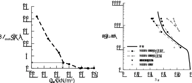
The deformation induced by wetting are reported as function of initial dry density in Figure 1.
As the objective of the study was to examine the behaviour of a collapsible soil therefore it
was decided to prepare the model with a low dry density (14.5 kN/m
3) and band w= 13%
(Sr≅42%).
The soil water retention curve has been obtained under suction controlled condition for
different void ratios. In Figure 2 are reported the curve obtained in oedometer cell under
suction controlled conditions; the branch of SWRC obtained by Mercury Intrusion
Porosimetry on a samples compacted at the dry unit weight of 14.5 kN/m
3and the point
obtained from equalization stage in oedometer and triaxial cell (Casini et al 2012
i). It was
2
decided to prepare the sample at a Sr≅42% (e
0=0.82) which correspond a suciotn s≅200 kPa
so all the point follows the wetting branch of soil water retention curve when the sample is
connected with the water at base in order to avoid the effects of hysteresis
Figure 1 Deformation at saturation- initial dry unit weight. Figure 2 SWRC obtained at different void ratios
2 EXPERIMENTAL APPARATUSES
The samples was compacted statically in a cylindrical container using a 5.0 ton load frame. The procedure set-up used it was the same of previous campaigns performed at ENPC (Cui et al.2005ii). It have been prepared in total eight samples (each one weight 35 kg), the properties are reported in table 2 (Casini et al. 2012 in prepiii.).
Sample w (%) γd (kN/m3) σvc (kPa) Laboratory F-1 13.17 14.36 296 ENPC F-2 16.85 14.12 65 ENPC I-A 13.9 14.30 189 LCPC I-B 13.28 14.24 220 LCPC I-C 13.75 14.54 196 LCPC II-D 13.75 14.44 208 LCPC II-E 15.1 14.29 180 LCPC II-F 12.54 14.57 215 LCPC
Table 2. After compaction properties of the samples used in the centrifuge
In Figure 3 is reported the instrumentation and its position on the sample. It was installed six tensiometers (five in the first campaign) on the diametral opposite sides. Three tensiometers provided by CERMES (labelled ENPC) and three provided by Durham University (labelled DU) in the figures. The elevation are reported in the figure 3. One water pressure transducer was installed at the base of metallic container in the sandy layer in order to control the water pressure in the model.
12 13 14 15 16 17
γ
d0(kN/m
3)
0 5 10 15 20 25Δε
asat (%) 0 0.2 0.4 0.6 0.8 1 Sr 1 10 100 1000 s (kPa) MIP oedometer e0=0.80 oedometer e0=0.73 triaxial cell oedometer3
Figure 3. Instrumentation on the sample in centrifuge.A circular metallic disk (foundation) has been put in the centre of the sample. Load was applied through a spherical hinge to avoid any overturning moment and eccentricity. The load of foundation was performed at a constant displacement rate and the resulting load measured by a load cell. Four LVDT allowed for measuring the vertical displacements at the top of the sample along four radii regularly distributed around the axis of foundation at a distance close to 10 cm (one alone at a distance close to 3 cm in the second campaign).
3 RESULTS
The load of foundation was performed for three height of water level. Defined Hw the height of
water level measured from bottom of layer, H the height of layer (Figure 4), the load of foundation was performed for Hw=H, Hw =H/2 and Hw=0.
Figure 4. Water level in the model
The evolution of pore water pressure and displacement measured during the test D, are
reported in Figure 5 with the comparison with the prediction of a FEM analysis performed
with code_bright using the Barcelona Basic Model. An attempt to simulate the effect of
increasing the gravity acceleration from 1g to Ng, with N=50 is also perfomed.
Tensiometer ENPC Tensiometer DU D 24 D 56 D 59 D 119 85 25 70 90 30 0 300 Foundation φ = 30 mm Displacements sensor Water pressure sensor Soil Sand Geotextile 50g Direction of rotation ENPC (top) DU (top) DU (middle) DU (bottom) ENPC (middle) ENPC (bottom) Hw H