Copyright © 2019 by Francesca Brusciotti, Ilaria Giannetti, Andrea Micheletti, Shirley Nwokoye, Diego Ruggeri, Giuseppe Ruscica
Published by the International Association for Shell and Spatial Structures (IASS) with permission.
Tribute to Kenneth Snelson
Francesca BRUSCIOTTIa, Ilaria GIANNETTIa, Andrea MICHELETTIa*, Shirley NWOKOYEa, Diego RUGGERIb, Giuseppe RUSCICAc
a Department of Civil and Computer Science Engineering, University of Rome Tor Vergata
Via Politecnico 1, 00133, Rome, Italy [email protected]
b Lamellazione Srls, Ciampino, RM, Italy
cDepartment of Engineering and Applied Sciences, University of Bergamo, Italy
Abstract
This paper presents the project of a tensegrity pavilion dedicated to the memory of Kenneth Snelson (1927-2016), the American artist who invented tensegrities and popularized them with the sculptures he built worldwide. The shape of the pavilion, based on a combination of X-Modules, is that of a “gate”, so that when walking through it, one can observe on the sides and above the transparent “floating-compression” arrangement of struts and cables. The choice of materials employed in the construction – bars in fir-wood for struts and recycled sailing ropes for cables - is also inspired by the Snelson’s tensegrity primary plywood “X-Piece”, complying with a fabrication and assembly procedure conceived to maximize simplicity and recyclability. The form finding of the pavilion was carried out by energy minimization on a virtual elastic structure, while for the structural design, a linearized static and dynamic analysis was performed considering own weight load and live loads. The geometry developed for the nodal connections between struts and cables has been realized by the Italian company Progetto Legno, according to a customized fabrication process.
Keywords: form finding, tensegrity, x-form.
1. Introduction
We present the project of a tensegrity pavilion for the Form and Force exhibition/competition organized by IASS WG21. The pavilion is dedicated to the memory of Kenneth Snelson (1927-2016), the American artist who invented tensegrities and popularized them with the sculptures he built worldwide [5]. The pavilion’s design is based on the sculpture “X-planar Tower” (1962-88), which in turn is derived from Snelson’s tensegrity primary plywood “X-Piece” (1948). As Snelson explained in his picture essay, “Tensegrity, Weaving and the Binary World” [1], X-Modules can be combined together in space-filling assemblies which can be extended to any length in all directions. The shape of the presented pavilion, based on a combination of X-modules, is that of a “gate”, so that when walking through it, one can observe on the sides and above the transparent “floating compression” arrangement of struts and cables. The choice of materials employed in the construction is also inspired by the X-Piece, complying with a fabrication and assembly procedure conceived to maximize simplicity and recyclability.
2
2. The X-Form
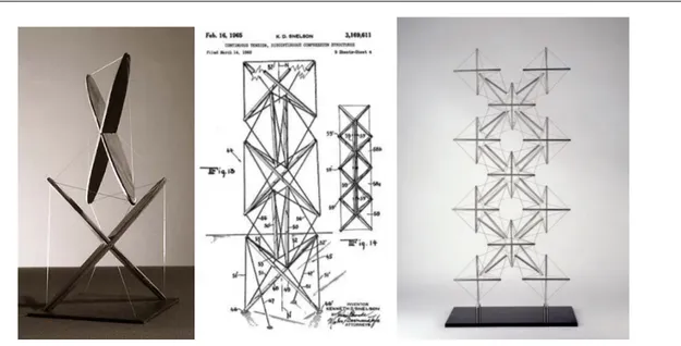
Snelson developed his first sculpure in the autumn of 1948, after attending Buckminster Fuller courses, on structural geometries, at Black Montain College Summer School in North Carolina. As Snelson told, the first “X-Piece” sculpure, was the result of the evolution of a first mobile sculpure concerned with balance of successive modular elements (clay weights) suspended one-to-the-next by means of thread-slings. With the aim to replace the clay weights with additional tension lines to stabilize the modules one to another, he invented "X" kite-like modules, out of plywood. Thus, as Snelson explained “while forfeiting mobility, I managed to gain something even more exotic, solid elements fixed in space, one-to-another, held together only by tension members” [2]. After a further discussion with Fuller in the Black Montain College summer school of 1949, the original X-Piece, kite-like in plywood (Fig. 2), was deveoloped by Snelson in correct tensegrity geometry, replacing playwood struts with metal bars (Fig. 3). In 1959, the original “X-Piece”, together with a series of four “model of tensegrity”, were presented at the MoMA of New York, within the monographic exibithion dedicated to the work of Bukminster Fuller, as a witness of Snelson invention [3]. In 1960, the invention was filed as a patent titled “Continuous tension, discountinuos compression structures” by Snelson (Fig. 2) [4].
The X-Piece turns into a real tensegrity by replacing an “Edge” cable with a strut connected to the structure with four “Sling” cables (Fig. 3). This new structure is stabilized by adding two “Draw” cables. The Draws connects the ends of the new strut to the farthest end of the other two struts, so as to move one strut away from the other, without allowing them to touch each other. The evolution of the X-Piece is the X-form.
What does X-Form consist of? Instead of replacing one Edge cable with a strut, a second X-Module is placed (Fig. 3). This assembly is the first step in a construction process that can be extended indefinitely along the three Cartesian directions.
Figure 1: Snelson in his studio in New York in 1960 (left, picture from [5]). Ken On Tower (right, picture from [4])
3
Figure 2: “X-Piece” in plywood, 1948 (left); Snelson Tensegrity patent, 1965 (center); “X-planar Tower” 1962-1988 (right). Pictures from [4].
Figure 3: X-Form, assembling modules (pictures rearranged from [1]).
4
3. Pavillon geometric design
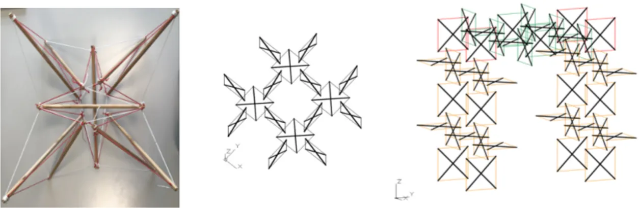
The shape of the pavilion is obtained by laying the X-Form on the top face and the two opposite lateral faces of a cube. The idea is to obtain a “gate”, so that when walking through such structure, one can observe on the sides and above the transparent “floating-compression” [2] arrangement of struts and cables. The way of assembling modules is a critical point in the design process (Fig. 5). A physical model was built on the basis of a “star” of modules, using wooden struts and synthetic cables (Fig. 5, left). Other than experimenting form finding physically, this model provided insight about the problem of determining the level of selfstress that is necessary to apply to cables in order to obtain a uniformly stressed structure.
Figure 6: Views of the Pavilion after form finding.
Figure 5: Pavilion geometry: ‘star’ structure (left); ‘plate’ structure (center); angle connection between ‘plates’ (right).
5
the sides of four X-Modules. From these supports, two “walls” consisting of 14 X-Modules each, are erected to connect with the three-dimensional transparent roof, composed by a dense repetition of elements. The walls and the roof are formed by joining stars together. In this way, while on the front the assembly appears with a rectangular feature, on the sides the X-Form appears with its original star-shaped feature, and it looks like it is laying on the ground on single vertices.
4. Realization
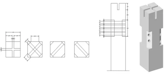
The choice of fir-wooden bars for struts is crucial for the realization of the Pavilion. With respect to struts design, the use of wood maximize simplicity and economy in fabrication and assembly procedure. On this purpose, a special node was studied and designed, in order to eliminate additional fitting in the connections between elements. Slits and holes, as shown in Fig. 7, are easily realized at every bar end section to accommodate the ropes. Cross slits allow cables to be positioned and fixed with a simple knot. Holes accommodate the Draw cables, which have the function of tensioning elements for prestressing the structure in a controlled way. Such holes are drilled in an angular fit obtained by flattening the side edges at the end section of the bar (Fig. 7), and the knots are slightly hidden in the flattened area.
Cables are recycled sailing ropes in synthetic fibers. The idea of recycling was the driving concept of the node design, which have been performed in order to optimize the construction process. Indeed, slits and holes allow one to anchor the cables with simple knots and shims - and to adapt to any particular configuration of bars in space, making the structure reusable several times in new forms. On this purpose, the geometry of nodes was studied with the Italian company Progetto Legno, according to a customized fabrication process, thanks to craftsmanship expertise in wooden construction.
Figure 7: Details of the strut ends.
6
5. Numerical model: form finding and structural analysis
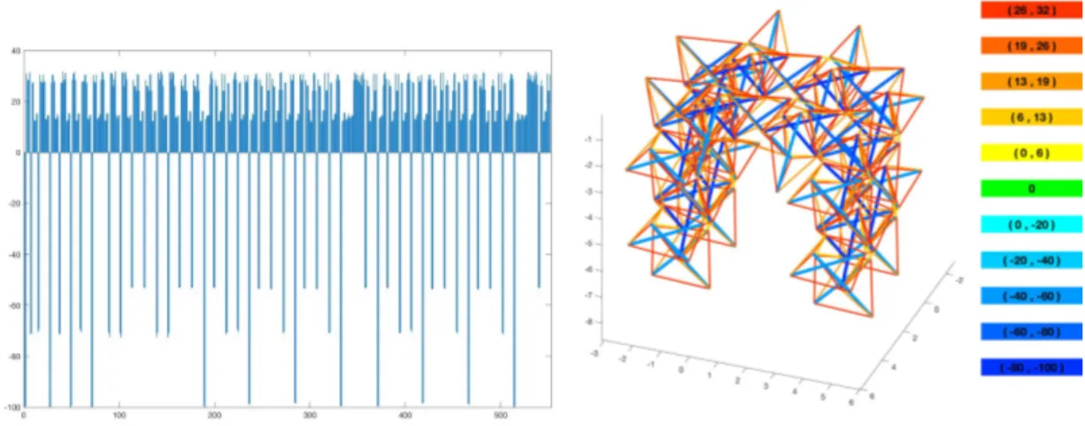
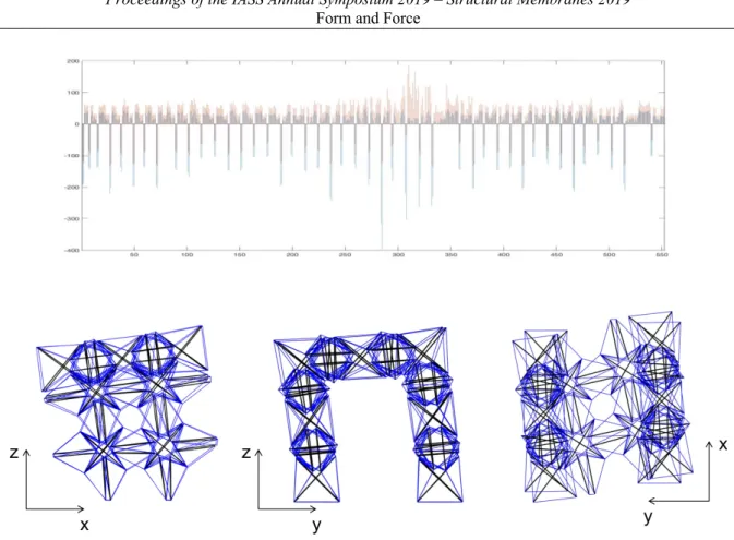
The design of the pavillion has been perfomed as follows. Once the overall geometry and the X-Form has been decided (structure covering three faces of a cube, relative arrangement of X-Modules), a form-finding procedure has been carried out by minimizing the elastic energy of a virtual structure, with fictitious elastic properties, considering very ‘soft’ elastic cables. The form-finding allowed us to obtain a pattern of forces in space in stable equilibrium with the desired shape, corresponding to a prestress state in the elements (Fig. 8). Such prestress state is then rescaled to match material properties and loads of the real structure, verifying that maximum allowed stresses are not exceeded (Fig. 9). Finally, fine tuning of geometry and prestress is performed to maximize structural performances. A linearized dynamic analysis is then performed under own weight load to compute natural frequencies and vibration modes (Fig. 10).
Figure 8: Equilibrium stresses after form finding, bar plot (left) and colormap (right), normalized with respect to a maximum compressive value of -100.
Figure 9: Maximum (left) and minimum (right) stresses, reported as ratio between actual stress and (tensile/compressive) member strength..
7
Figure 10: (top) bar plot of the actual member stress in kgf; (bottom, from left to right) deformed shapes in the first, second, and third mode of vibration.
Acknowledgements
We wish to thank professor Stefania Mornati (Department of Engineering and Computer Science – University of Rome Tor Vergata) for putting in contact the academic side and the industry side of this project, within her research interest in wooden contructions. We are grateful to Lorenzo Botti and the company Progetto Legno for providing the wooden struts and performing the machining of the end sections. AM gratefully acknowledges the financial support from the Italian Ministry of Education, University, and Research (MIUR) under the FFABR grant L.232/2016.
8
Figure 11: artistic view of the pavilion.
References
[1]
K. Snelson, Tensegrity, Weaving and the Binary World, 2014, downloaded in 2019 from www.kennethsnelson.net.[2] R. Motro, Tensegrity: Structural Systems for the Future, Kogan Page Science, London, 2003. (Letter from Kenneth Snelson to R. Motro, published in November 1990 in “International Journal of Space Structure”).
[3] MoMA Archive, Exhibition 652, Bukminster Fuller, October 23-novembre 22, 1959 Master checklist.
[4] K. Snelson, The Art of Tensegrity, International Journal of Space Structures, vol, 27, 2012, pp.71-80
![Figure 1: Snelson in his studio in New York in 1960 (left, picture from [5]). Ken On Tower (right, picture from [4])](https://thumb-eu.123doks.com/thumbv2/123dokorg/7594663.113711/2.892.108.768.753.1046/figure-snelson-studio-york-picture-tower-right-picture.webp)