Contents lists available atScienceDirect
Applied Energy
journal homepage:www.elsevier.com/locate/apenergy
Integrating cogeneration and intermittent waste-heat recovery in food
processing: Microturbines vs. ORC systems in the co
ffee roasting industry
Antonio M. Pantaleo
a,b,⁎, Julia Fordham
a, Oyeniyi A. Oyewunmi
a, Pietro De Palma
c,
Christos N. Markides
aaClean Energy Processes (CEP) Laboratory, Department of Chemical Engineering, Imperial College London, South Kensington Campus, London SW7 2AZ, UK bDepartment of Agro-environmental Sciences, University of Bari, Via Amendola 165/A, 70125 Bari, Italy
cDepartment of Mechanics, Mathematics, and Management, Polytechnic University of Bari, Via Re David 200, 70125 Bari, Italy
H I G H L I G H T S
•
A novel intermittent waste heat recovery system is investigated for coffee roasting processes.•
A real case study of a major coffee roasting firm is proposed.•
A techno-economic comparison of CHP and waste heat recovery configurations is provided.•
Key techno-economic factors influencing investment profitability is proposed. A R T I C L E I N F OKeywords: Coffee roasting Intermittent heat recovery Micro gas turbine Organic Rankine cycle Waste heat recovery
A B S T R A C T
Coffee roasting is a highly energy intensive process wherein a large quantity of heat is discharged from the stack at medium-to-high temperatures. Much of the heat is released from the afterburner, which is required to remove volatile organic compounds and other pollutants from theflue gases. In this work, intermittent waste-heat re-covery via thermal energy storage (TES) and organic Rankine cycles (ORCs) is compared to combined heat and power (CHP) based on micro gas-turbines (MGTs) for a coffee roasting plant. With regard to the former, a promising solution is proposed that involves recovering waste heat from theflue gas stream by partial hot-gas recycling at the rotating drum coffee roaster, and coupling this to a thermal store and an ORC engine for power generation. The two solutions (CHP + MGT prime mover vs. waste-heat recovery + ORC engine) are in-vestigated based on mass and energy balances, and a cost assessment methodology is adopted to compare the profitability of three system configurations integrated into the selected roasting process. The case study involves a major Italian roasting plant with a 3,000 kg per hour coffee production capacity. Three options are in-vestigated: (i) intermittent waste-heat recovery from the hotflue-gases with an ORC engine coupled to a TES system; (ii) regenerative topping MGT coupled to the existing modulating gas burner to generate hot air for the roasting process; and (iii) non-regenerative topping MGT with direct recovery of the turbine outlet air for the roasting process. The results show that the profitability of these investments is highly influenced by the natural gas and electricity prices and by the coffee roasting production capacity. The CHP solution via an MGT appears as a more profitable option than waste-heat recovery via an ORC engine primarily due to the intermittency of the heat-source availability and the high electricity cost relative to the cost of natural gas.
1. Introduction
Waste heat recovery in industry is a topic of great importance and has been attracting growing interest from diverse stakeholders[1]. In particular, the food processing sector is a highly energy-intensive in-dustry, which makes up 7% of total EU energy consumption[2], with around 57% of the primary energy input being lost as waste heat during
the production[3]. Several investigations have been performed with the aim of improving the efficiency of food production, including heat and power cogeneration cycles[4]and waste heat recovery systems [5]. Some studies propose waste heat recovery for drying or preheating food products[6], or for other purposes such as space or district heating [7]. When the waste-heat stream has a sufficient temperature level, it can be used for power generation via mature technologies such as the
https://doi.org/10.1016/j.apenergy.2018.04.097
Received 9 January 2018; Received in revised form 13 April 2018; Accepted 28 April 2018
⁎Corresponding author at: Department of Agro-environmental Sciences, University of Bari, Via Amendola 165/A, 70125 Bari, Italy. E-mail addresses:[email protected],[email protected](A.M. Pantaleo).
0306-2619/ © 2018 The Authors. Published by Elsevier Ltd. This is an open access article under the CC BY license (http://creativecommons.org/licenses/BY/4.0/).
Kalina cycle[8], or the organic Rankine cycle[1,9,10], or even earlier-stage technologies currently under development such as thermoacustic [11]or thermofluidic heat engines[12]. In particular, the Non-Inertive-Feedback Thermofuidic Engine (NIFTE) [13,14] and the Up-THERM heat converter [15,16]have been shown to be competitive with es-tablished technologies, such as ORCs[17], due to their small number of moving parts, and low capital and running costs. Nevertheless, ORC technology is more established, commercially available and has been selected for the present study.
Intermittent heat recovery applications can be included, such as sintering processes[18], or furnaces in steel manufacturing[19]and combined cycles where cogenerated heat from onsite power production is combined to waste heat streams[20], with the possibility to adopt multi-fuel energy sources[21]. Most of the heat recovery studies have been focused so far on continuous processes, with limited attention to recovering waste heat from batch processes [22]. However, around 50% of industrial food processes use batch processes, which are typi-cally needed to improve the quality and consistency of the product[23] such as coffee roasting[24], dairy pasteurization [25]and alcoholic beverage production [26]. The drawback of batch processes is the substantial amount of waste heat emitted intermittently and at variable temperature level, preventing conventional heat recovery methods from being used. Waste heat recovery from batch processes in industrial and food processing sectors have been investigated in the literature implementing heat integration approaches [27], optimising the plant layout[28]and improving the efficiency of the process through heat stream analyses[29]. Heat integration can be either direct or indirect [30], the latter requiring a thermal energy storage (TES) system[31]. TES systems have been shown to be the most successful for recovering waste heat in industrial batch plants [32], including food processing applications and multipurpose batch plants[33].
The present work considers a techno-economic analysis of a waste-heat recovery system for an intermittent coffee-roasting process based on the integration of a TES system with an ORC plant. The novelty of this study is in the optimization of the ORC engine for steady-state operation, considering different working fluids and temperature levels, and in the decoupling of the operation of the ORC plant from the in-termittent waste-heat source supply via proper sizing of the TES. The profitability of the proposed solution is verified with respect to standard alternative solutions based on the use of natural-gas-fired (NG) cogen-erative micro gas-turbines (MGTs).
The case study of a major coffee processing plant with a 3000 kg/h production capacity and the Italian electricity/(NG) cost scenario are used for the techno-economic assessment. Three technical solutions for increasing the efficiency and reducing the energy costs of the coffee
roasting process are considered: (1) intermittent waste-heat recovery from the hot flue-gases through an ORC engine coupled to TES; (2) regenerative MGT coupled to the existing modulating gas burner to generate hot air for the roasting process and electricity to match electric demand of the process; (3) non-regenerative MGT with direct recovery of turbine outlet air for the roasting process by means of an afterburner that modulates the heat demand of the roasting process. The investment profitability sensitivity to the main techno-economic process para-meters (i.e. daily roasting operating hours and avoided cost of elec-tricity) is discussed.
The relevance of the research relies in comparing different energy saving strategies integrated in the coffee production process in presence of intermittent waste heat source, and in identifying the key factors that influence their relative profitability. The conclusions and insights from this work are transferable to other batch food production processes. The coffee roasting process features and thermal storage options are in-troduced in Sections2 and 3, while Section4presents the methodology, Section5describes the application to the three case studies, Section6 reports the techno-economic input data and cost-benefit analysis, and finally Section7proposes a comparison of the investment profitability and a sensitivity analysis based on different CHP sizes. The results show that the profitability of these investments is highly influenced by the natural gas and electricity cost and by the coffee roasting production capacity.
2. Coffee roasting process
Coffee roasting is a unique source of intermittent waste heat due to the relatively high temperature of the exhaust gas and the typical cyclic process. The coffee roasting industry is a growing food processing segment with 6.7 billion kg of coffee being roasted every year[34]. It requires 11.2 × 10¹²kJ of input energy annually, with 75% of the en-ergy being wasted as heat through the stack[35]. A big challenge for roasting is to rapidly heat the air before introducing it into the batch. To achieve this rapid heating, the roasters use a very energy intensive and quite inefficient process.
Coffee roasting is a process that converts green coffee beans into beans that can be ground, brewed and consumed with a complex aroma and flavour. Coffee roasting technologies come in several different configurations with batch roasters and continuous roasters the most common[36]. Continuous coffee roasters involve a conveyor belt that slowly moves the beans through the furnace, roasting them con-tinuously and in large quantity. Batch coffee roasters operate in batches and allow higher process uniformity and quality of the beans. The op-eration of batch gas-fired coffee roasters equipped with afterburners is Nomenclature
Abbreviations
CHP combined heat and power LHV lower heating value MGT micro gas-turbine NG natural gas
ORC organic Rankine cycle PM particulate matter TES thermal energy storage VOCs volatile organic compounds Variables
cp,hr specific heat capacity of pressurized water in TES (J/kg K) ηORC thermal efficiency of ORC engine (%)
hE ORC and MGT plant operating hours (h/year)
hdrum enthalpy offlue gas in drum (J/kg) hin enthalpy offlue gas at MGT outlet (J/kg) ṁ gas turbine massflow rate (kg/s) mhr mass of water in the TES (kg) ṁhr massflow rate of water in TES (kg/s)
Pcond ORC workingfluid condensation pressure (Pa, bar) Pevap ORC workingfluid evaporation pressure (Pa, bar)
PE electric power output from MGT and ORC (W)
Q̇ thermal power recovered from cycle (W)
Q̇hr intermittent rate of heat transfer fromflue gases to TES
(W)
Q̇ORC constant heat transfer rate from pressurized water to ORC
(W)
Thr temperature of the pressurized water in the TES (°C) Thr,sup supply temperature of water in TES (K, °C)
Thr,ret return temperature of water in TES (K, °C) ẆORC net power output from ORC engine (W)
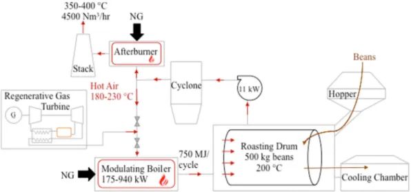
well known and widely described in literature[37]with emphasis on modelling the heat released from the process[38]and the effects on the beans being roasted [39]. In the case of batch coffee roasters, the roasting happens in cycles in which the green coffee beans enter the roasting drum and are heated to the desired temperature of 200–250 °C before being transferred to a cooling chamber[40]. A cycle lasts 10 to 20 minutes depending on the desired degree of roasting [41], and during this time the temperature gradient is kept constant. The roasting drum is a horizontal rotating chamber that rotates at a specified speed to induce mixing without the beans getting stuck to the walls from the inherent centrifugal force. Hot air is generated in a combustion chamber, usually fuelled by natural gas (NG), and passes through the roasting drum, directly heating the beans to the desired temperature. Thefirst stage of coffee roasting involves drying, i.e., evaporation of the water content in the beans, at temperatures between 160 and 190 °C [42]. After drying, the bean undergoes a series of chemical pyrolysis reactions at a temperature of 200–250 °C[43], which give the coffee its final flavour and aroma. During pyrolysis, there is also the release of volatile organic compounds (VOCs), carbon dioxide, and particulate matter (PM) from the roasted chaff that are added to the flue gases in the roasting drum[44]. When too many volatiles are released from the bean at temperatures above 200 °C, the aroma of the coffee can de-crease. For this reason, the temperature gradient during the process must be constant and a uniform and gradual heating of the beans from their surface to the core must be achieved. This is done by means of a modulating furnace that can control the heat provided to the roasting drum. A part of theflue-gas flow is returned to the combustion chamber at 180–230 °C through a heat exchanger to recover a fraction of the waste heat and increase the efficiency of the process via a semi-closed loop[45], as reported in the schematic ofFig. 1.
The VOCs, PM and CO2content in the remainingflue gas stream must be reduced before this is discharged into the atmosphere to comply with air quality standards. Therefore, theflue gas stream passes through a cyclone to remove particulates and then through an after-burner to combust pollutants that are released from the beans during the roasting phase. Finally, the steam is released through a chimney into the atmosphere at temperatures of 350–400 °C. Afterburners are an important part of the coffee roasting process as environmental emission regulations on particulate matter are becoming stricter in Italy[46]and around the world[47]. Two main types of afterburners are used: direct-fired and catalytic. The former fire the flue gas at extremely high temperatures of 760 °C and employ NG as fuel. The latter use catalysts to break down the flue gas pollutants chemically and require tem-perature around 400 °C. The catalysts need to be replaced every three to four years, resulting in higher operation and maintenance costs[48].
Due to the composition of theflue gas leaving the afterburner, some
of the compounds have the tendency to condense as the temperature drops during the heat exchange. This condensation on the surfaces of the heat exchanger, known as fouling, reduces the efficiency of the heat transfer and the overall heat recovery rate. The build-up of compounds lowers the thermal conductivity of the surfaces and the heat recovery potential drops[49]. Fouling can have major impacts on not only the efficiency of the process[50], but also on the equipment costs[51]. In addition, the build-up of condensates must be monitored and cleaned, increasing the maintenance and operational costs. If the fouling is ig-nored, more detrimental problems can arise, such as hot spots on the surfaces of the heat exchanger causing mechanical failure.
3. Thermal energy storage system
The recovery of intermittent waste heat requires the adoption of suitable thermal storage to decouple the heat source and the energy conversion process. Several studies have modelled and optimized the design of TES in intermittent processes [52], considering variable temperature levels[53]and phase-change materials (PCMs), integrated with ORCs [54]. The design of the TES and of the coupled energy-conversion systems depends on several technical factors (i.e. the size of batch process and the amplitude of thefluctuation of available waste heat) and economic factors (i.e. investment costs and avoided costs of onsite electricity). This justifies the adoption of classic thermo-eco-nomic optimization approaches, where the inter-relationships between component costs and their technical performance are taken into ac-count[55]. In particular, the optimal design of the TES strongly de-pends on the choice of the storage material and its operating conditions in specific intermittent processes[56]. When selecting a TES for re-covering of intermittent waste heat, sensible-heat storage using liquid water represents a low-cost solution over a range of application tem-peratures. The maximum temperature of liquid water storage depends on the boiling temperature of water at the considered operational pressure. Domestic hot water (DHW) and low temperature hot water (LTHW) storage are typically limited to maximum temperatures of 120 °C and pressure of 3 bar. For district heating and process-heat ap-plications, medium temperature hot water (MTHW) systems use cir-culating water at temperatures of 120–180 °C and pressures up to 11 bar, while high temperature hot water (HTHW) systems are designed for water temperatures of 180–220 °C and pressures up to 21 bar. In this case, hot water storage systems must be designed to allow for thermal expansion of the hot water as it is heated, and thus storage tanks are often designed to include a compressible gas cushion (steam, air or inert gas) to accommodate this expansion. Synthetic heat transfer oils (e.g., Therminol, Dowtherm) are a viable alternative for sensible heat storage at temperatures of 100–200 °C that do not require pressurization to
prevent boiling. This represents a trade-off in terms of the lower cost of storage vessel versus the higher cost of the storage media. Thermal storage using molten salts may be suitable for even higher temperature ranges (nitrate salts are typically used in concentrating solar power systems at temperatures of 390 °C), however specific system costs are comparatively high due to the material compatibility requirements for storage vessels, pumps, heat exchangers and pipelines[57]. Solid-liquid latent heat storage using organic or inorganic (salt-based) PCMs are an option that has recently received much attention for a range of appli-cations where compact TES is required[58], including small-scale ap-plications for solar thermal systems[59]. However, the costs of com-mercial PCM storage solutions are relatively high at present, in part due to the challenges associated with encapsulation and heat exchanger design. Some authors have also considered the potential of so-called “direct storage” in the ORC working fluid as it changes phase from li-quid to vapour[60]. While this potentially allows the omission of ad-ditional circulation loops and heat exchangers, the low energy storage density and the difficulty in maintaining a steady pressure of the vapour supply to the expander are major challenges[61,62].
4. Methodology and modelling approach
The present analysis investigates the possibility of exploiting an unsteady waste-heat source using an ORC engine. The best working conditions for such a plant can be obtained when it is optimized for steady-state operation. Therefore, we design the thermal energy storage system in order to attenuate the temperature variations of the heat source. We choose a low-cost pressurized water TES system whose ca-pacity has to be selected in order to guarantee a negligible temperature oscillation. This pressurized-water loop acts as the heat source for the subcritical and recuperative ORC engine, ensuring a constant avail-ability of heat to the engine. In this section, the model employed for designing the TES system and the optimization approaches for de-signing the ORC engine are described.
4.1. Thermal energy storage
The process of interest is periodic over a periodΔtand lends itself to TES. During this time interval, theflue-gas flow rate (in Nm3/s) varies linearly with time between a minimum (V̇min) and a maximum value, or
as:
= +
Vflue gaṡ ( )t Vmiṅ at (1)
whereais a suitable constant that can be known directly or found from the maximumflue-gas flow rate.
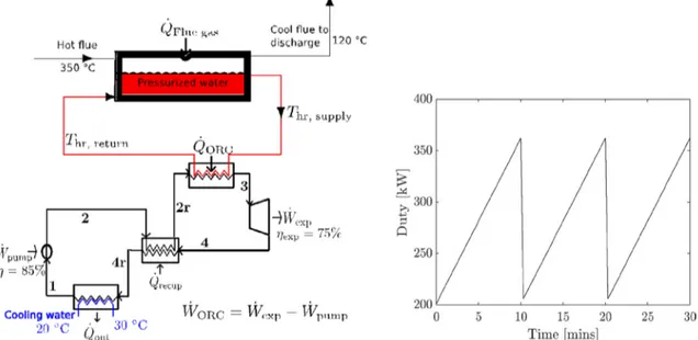
The TES system is composed of a pressurized water tank and two heat exchangers. In one of these heat exchangers, the water receives energy intermittently from the hotflue gases, as shown inFig. 2(right). On the other hand, the water provides the steady thermal power to the ORC plant in another heat exchanger. The unsteady energy balance over the TES system is written as:
= + V ρc T t Q Q t ( ) d d ̇ ̇ ( ) hr p hr hr ORC hr (2)
whereThr,ρhr,Vhr, andcp,hrare the temperature, density, storage volume
of the tank and specific heat capacity of the pressurized-water in the heat recovery loop, respectively. Here, Q̇ORCis the heat transfer rate
from the pressurized-water stream to the ORC workingfluid in the ORC evaporator:
= −
Q̇ORC m ċhr p,hr(Thr,sup Thr,return) (3)
whereThr,supand Thr,returnare the temperatures of the water at the outlet
and at the inlet of the tank. Q̇ ( )hr t is the (fluctuating) rate of heat
transfer from theflue gases to the heat recovery loop: =
Q̇ ( )hr t (ρcpΔTV ṫ ( ))flue gas (4) whereΔT is the temperature drop of theflue gases in the heat ex-changer.
The heat storage tank is modelled as a continuously stirred tank, assuming no heat losses to the environment. The dynamic model of the storage tank is a lumped model, with the assumption that the tank is well mixed and hence the spatial variation of the temperature within the tank is negligible. For the purposes of detailed engineering designs, other viable options may include multi-nodal tanks and stratified tanks, as well as molten salt and phase-change material systems.
The pressurized water circulation rate,ṁhr is determined by
bal-ancing the energy transferred from the flue gas with the energy re-ceived by the ORC evaporator over a cycle:
∫
= −ρc T V t t m c T T t
(( pΔ ))flue gas t ̇ ( )d ̇ (( ))Δ
0 Δ
flue gas hr p,hr hr,sup hr,return (5)
The pressurized water is returned to the storage tank at a constant temperature (Thr,return), while it can be supplied to the ORC engine at a
Fig. 2. Left: Schematic of pressurized-water heat recovery unit and recuperative ORC engine. Right: Temporal profile of the thermal power supplied to the TES system (values are referred to the application described in next section and to the assumption of TES temperature of 100 °C).
“set-point” temperature (Thr,sup) ranging from 100 °C to 150 °C. This
temperature range has been selected to ensure the thermal stability of the ORC workingfluids. In general, the temperature of the water in the tank is affected by temporal variations. However, for a sufficiently large value of the volume of the tank, the oscillations of the water tem-perature around the set-point value become negligible and a steady value of the heat power transferred to the ORC plant can be guaranteed.
4.2. ORC engine design
The ORC engine, shown inFig. 2(left), is assumed to be subcritical, due to the low temperature of the heat source (the pressurized water); the system also features a recuperator or an internal heat exchanger to improve its thermal efficiency and power output. In the heat ex-changers (evaporator, condenser and recuperator), the energy balance is carried out on both the hot and cold streams, with the assumption of no heat losses in the system, isobaric processes, and with a minimum temperature difference ΔTmin= 10 °C [5,63]. The cycle calculations have been performed neglecting the small temperature variation of the supply temperature and considering a constant set point temperature, Thr,sup.
The required power of the pump is calculated by using an isentropic efficiency ηs,pump: = − = − W m h h m h h η ̇ ̇ ( ) ̇ ( s ) pump wf 2 1 wf 2, 1 s,pump (6)
whereṁwfis the massflow rate of the working fluid, h is its enthalpy,
the subscript “s” indicates isentropic conditions, and ηs,pump is the
isentropic efficiency of the pump, which is set to 85%.
The temperature of the workingfluid at State 3 can vary between the dew point temperature at the evaporation pressure (no super-heating) and its maximum allowed temperature (i.e., Ths,sup− ΔTmin), corresponding to the maximum degree of superheating (θsh):
= − − − θ T T P T T T P ( ) Δ ( ) sh 3 dew evap
hs min dew evap (7)
with0⩽θsh⩽1.
Assuming an isobaric heat-addition process, the rate of heat input from the heat source is given by:
= − = −
QORĊ ṁwf(h3 h2r) m ċhr p,hr(Thr,sup Thr,return) (8) while the power that can be extracted from the cycle in the expander is given by:
= − = −
Wexṗ ṁwf(h3 h4) ηs,expṁwf(h3 h4,s) (9)
with the isentropic efficiencyηs,expset to 75%, which is in the middle range of literature values.
The thermal power exchanged in the recuperator is given by:
= − = −
Q̇out ṁwf(h4r h1) ṁwf(h2r h2) (10) with heat rejected from the ORC in the condenser to the heat sink such that:
= − = −
Q̇out ṁwf(h4r h1) m ċcs p,cs(Tcs,out Tcs,in) (11) where the inlet and outlet temperatures of the heat sink are set to
Tcs,in= 20 °C and Tcs,out= 30 °C.
Finally, the efficiency of the ORC engine is defined as:
= = − η W Q W W Q ̇ ̇ ̇ ̇ ̇ ORC net ORC exp pump ORC (12)
Several low-temperature ORC workingfluids have been compared in this work, results for which are later reported inTable 3andFig. 6. The workingfluids are the alkanes, butane and pentane, the refrigerants R227ea and R245fa, and the more recent refrigerant blends R1233zd, R1234yf, and R1234ze. For more advanced methodologies aimed at
simultaneous ORC system optimization and working-fluid design, but which are beyond the scope of this paper, the interested reader can refer to Refs.[64–66].
With the thermal storage as the heat source, the ORC engine is designed to maximize its net power output,Ẇnet, for each of the selected
workingfluids using the interior point optimization algorithm[67]. The following constraints are imposed:
⩾ T T Δpinch Δmin (13) ⩾ T4 Tdew(Pcond) (14) ⩽ ⩽
Pcond Pevap Pcrit (15)
⩾
Pcond 1bar (16)
Thefirst constraint in Eq.(13) ensures that the heat exchangers (evaporator, condenser and recuperator) are designed such that their pinch-point temperature difference (ΔTpinch) is greater than a set
minimum ( TΔmin) of 10 °C. In addition,T4, the turbine outlet
tempera-ture, is constrained to be higher than or equal to the dew point tem-perature at the condensation pressure (Eq.(14)) so that the working fluid at the turbine outlet is always in the vapour state and there is no chance of liquid droplet formation in the expander, so ensuring that the challenges associated with wet expansion are avoided. To reduce ca-pital costs, the system is kept subcritical (Eq. (15)) by keeping the evaporation pressure below the critical pressure. Finally, by the con-straints of Eq.(16), the condensation pressure must be equal to or larger than the ambient pressure to avoid sub-atmospheric pressures in the cycle and consequently high component costs.
4.3. Cost analysis
The cost assessment of the ORC unit has been carried out con-sidering the coffee roasting heat exchanger, the TES, the ORC pump, ORC heat exchangers and ORC expander addressed individually, in order to calculate the turn-key cost of the system. A dual stage screw expander has been selected. In the comparative case of MGT, cost component data have been assumed directly from manufacturers.
The cost correlations chosen for the heat exchanger and pumps are those from [68], subsequently normalised to 2018 prices using the Chemical Engineering Plant Cost Index (CEPCI).
For each double-pipe heat exchanger, the cost CHXis given by[68]:
= + C F F e A HX m p 7.146 0.16·ln(10.7639· ) (17) = + ⎛ ⎝ − ⎞ ⎠+ ⎛ ⎝ − ⎞ ⎠ > F 0.8510 0.1292 P 1.013 P P 41.37 0.0198 1.013 41.37 for 42.383 bar(a) p 2 (18) where A is the total heat transfer area in m2andF
m accounts for
ma-terial costs, equal to 2 for a stainless steel inner pipe and carbon steel outer pipe and 3 for both pipes in stainless steel. The former is used for the ORC unit, while the stainless-steel outer pipe is required for the intermittent heat recovery system coupled to the coffee roasting flue gases and charging the thermal energy storage, as a consequence of the corrosive properties of these gases. Fpis a pressure factor, equal to 1 for pressures P below 42.383 bar(a) (600 psig) and evaluated by Eq.(18) for pressures above this value.
For the pump and motor[68]: = + − + + + + − C S W e e ( , ̇ ) P S S W W W W p m 9.72 0.602·ln 0.0519·(ln ) 5.83 0.131·ln ̇ 0.0533·(ln ̇ ) 0.0286·(ln ̇ ) 0.00355·(ln ̇ ) p p2 m m2 m3 m4 (19) ⎜ ⎟ = ⎛ ⎝ ⎞ ⎠ S V P ρg 15,850· ̇ · 3.2808Δ p 0.5 (20) where Sp is a pump size factor, and Ẇm is the motor power in
horsepower (HP).
Costs for the screw expander(s) CE,sare taken from[69], who de-veloped a correlation based on costs for refrigerant screw compressors:
= +
CE,s 231,300 ̇Vout 3344.4 (21)
where V̇outis the volumetricflow rate at the expander exhaust in m3/s. The two stages of the screw expander are assessed individually using the same correlation.
The power block cost of the ORC engine is approximated by the sum of the component costs: evaporator, condenser, pump and motor, and expander. This is subsequently converted into a total capital investment for the ORC, factoring in site preparation, service facilities, con-tingencies, start-up costs, and contractors’ fees. The power block ac-counts for 77% of the ORC capital investment once these costs are in-cluded.
4.4. Levelized cost of energy and economic analysis
The Levelized Cost of Electricity (LCE) is calculated assuming op-eration of the ORC and MGT systems only during the roasting plant operation, i.e. when intermittent waste heat is available:
= + LCE f I C N P h · · · a T,C C E E (22)
where NCis the number of roasting cycles per year; hErepresents the plant annual operating hours; fais the annuity factor calculated by Eq.
(23), with r being the cost of capital and Vuthe investment lifetime: = − + − − f r r 1 (1 ) V (years) a u 1 (23) Moreover, I is the investment cost, CT,Cis the operating cost (fuel and maintenance) during each roasting cycle and PE represents the installed electric power. This operation mode is the only one available in the case of intermittent waste heat recovered by ORC (Case 1 of next section), unless an external heating source is adopted, to integrate the heat source when the roasting process is not in operation, which is an option not addressed here. On the contrary, in the case of cogenerative MGT (Case 2 and 3 of the next section) the CHP can operate in-dependently from the roasting process and generate electricity base-load; this electricity can be consumed onsite to match the process de-mand or fed into the grid. The operation strategy influences the investment profitability, since the electricity revenues can be re-presented by: (i) the avoided cost of supply, in case of onsite con-sumption and contemporarily generation and demand; (ii) the elec-tricity feed-in price, in case of sales to the grid; (iii) a share of the cost of
supply, when the net metering option is assumed and electricity is fed into the grid when exceeding the demand and withdrawn when demand exceeds generation (in this case the electricity cost components of transport, distribution and dispatching are usually charged to the end user). For this purpose, in the proposed methodology for revenues calculation and profitability analysis, the specific electric load profile and cost of electricity of thefirm is considered, to evaluate the con-temporaneity of electricity generation and demand. Moreover, the Italian energy regulatory framework for decentralized and onsite gen-eration is considered, with the assumption to operate in net metering to the grid and generate, on an annual basis, the same quantity of elec-tricity consumed by the load. This allows a fair comparison between the most profitable operating strategy for studies of onsite cogeneration via MGTs and intermittent waste heat recovery via ORCs.
Thefinancial appraisal of investment is carried out assuming the following hypotheses: 20 years of plant lifetime (VU); no‘re-powering’ throughout the 20 years; zero decommissioning costs; capital assets depreciated using a straight-line depreciation over 20 years; cost of capital (net of inflation) r equal to 5%; corporation tax neglected; no capital investments subsidies; maintenance costs, fuel supply costs, electricity and natural gas prices held constant (in real 2018 values).
5. Application to the selected coffee roasting plant
The coffee roasting production site considered in this study is a large plant in Italy with a roasting capacity of 3000 kg/h. The plant operates 6 h per day (1560 h per year). The site comprises two roasting units of 250 kg of beans per cycle respectively, with each cycle lasting 10 min. The modulating burners and afterburner are both fuelled by NG. Each cycle requires 1.5 MJ of thermal energy per kg of beans, or 375 MJ per cycle. Operating the plant for 6 h per day and 5 days a week requires 7020 GJ of natural gas and 800 MWh of electricity per year. The modulating burner operates in the range of 175–940 kW and the tem-perature of the exhaust gas from the stack is in the range 350–400 °C (this temperature is controlled modulating the NG flow rate in the afterburner). A schematic of the investigated roasting process is shown inFig. 3, which reports the total energy consumption and roasting ca-pacity per cycle (sum of the two roasting units).
The roasting process discharges medium/high temperature heat, and it is possible to improve the overall efficiency recovering the thermal energy content of theflue gases via an ORC engine, as de-scribed below. The performance and profitability of such a technology are compared with two more standard solutions consisting of re-covering thermal energy from a topping MGT plant.
5.1. Case Study 1: Waste-heat recovery via ORC
An ORC system is combined with the roasting plant through the use of a TES system recovering the intermittent waste heat from the afterburner, as shown by the scheme in Fig. 4. We assume that the roasting process lastsΔt = 10 min. The flue gases exit the afterburner at temperature in the range of 350–400 °C and at a flow rate that varies linearly between 2500 and 4500 Nm3/h in each 10-min cycle. With these assumptions, the coefficients in Eq.(2)areV̇min=0.6944Nm3/s and =a 9.259×10⁻⁴Nm3/s2.
The temperature drop of theflue gas in Eq.(5)is kept constant at 230 °C, while the input temperature is in the range 350–400 °C, so achieving a correspondent TES temperature in the range of 100–150 °C. The pressurized water is returned to the storage tank at a constant temperatureThr,return=90 C° . For each value of the set-point tempera-ture100°C⩽Thr,sup⩽150 C° ,ṁhris calculated by Eq.(5). It follows that
over each cycle an average value of thermal power equal to 288 kW is supplied to the ORC during the coffee roasting process.
Three key variables relevant to the size of the pressurized water storage tank volume (Vhr) have to be minimized: (1) charging time; (2)
investment cost of the storage; (3) fluctuations ofThr,sup to ensure a
fairly constant power production from the ORC engine. Thefirst two require the storage volume to be minimized while the third requires the volume to be maximized, hence a balance must be struck. In terms of the charging time, we assume that at the start of operation the tem-perature of the storage system can be increased from ambient condi-tions (∼20 °C) to the set point in two cycles or less (i.e., < 20 min). The fluctuations in the supply temperature (Thr,sup) around the set point are
also expected not to exceed ± 2 °C, to not affect the ORC operation. The charging time of the storage system at different storage volumes is re-ported in Table 1. It has been computed by Eq.(2)withQ̇ORC=0. Moreover, integrating Eq.(2)in time, after substitution of Eq.(3)for
Q̇ORC, thefluctuations of the supply temperature around the set point
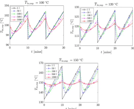
can be obtained. These temperaturefluctuations are reported inFig. 5 for three values of the set-point temperature andfive values of the tank volume. As expected, the lower storage volumes provide faster charging for the storage system, with charging times less than a cycle period (< 10 min). However, the storage volumes between 1 L and 100 L offer no significant improvement to the storage system in terms of mini-mizing the supply temperature fluctuations, with fluctuations ex-ceeding ± 5 °C in the 120 °C case and exex-ceeding ± 10 °C in the 150 °C case. The fluctuations in the supply temperature fall below ± 2 °C and ± 1 °C when the storage volumes exceed 500 and 1000 L, respec-tively. While higher storage volumes (e.g., > 500 L) will lead to better smoothening of the supply temperature, they will lead to very high charging times, exceeding 3 cycles when Vhw= 1000 L. Thus, the
thermal storage is designed with an intermediate volume of 500 L,
which gives fluctuations below ± 2 °C and charging times less than 20 min (2 cycles/periods).
The ORC power system is optimized for maximum power produc-tion and the results of the simulaproduc-tion are presented in Table 2and Fig. 6. For brevity,Table 2provides only the results forThr,sup=120°C and Thr,sup=150°C, using, butane, pentane, R227ea, R245fa, and R1234ze, whereas, Fig. 6 shows the maximum power and the re-cuperated thermal power for allfluids and set-point temperatures in the range 100–150 °C. In order to keep the system subcritical, the eva-poration pressures of the workingfluids are constrained to a maximum of 95% of the critical pressure[70,71]. It should be noted that while the same amount of heat (∼288 kW) is supplied in all the cases, the pres-surized waterflow rate (ṁhr) varies with the heat supply temperature as
dictated by Eq.(6), such that, for example, theflow rate for the cases with set point temperature of 120 °C (ΔThr= 30 °C) is double than that for the 150 °C cases (ΔThr= 60 °C).
However, the power output increases with the supply temperature; at a supply temperature of 100 °C, the ORC engine delivers between 20 kWe and 24 kWe while it delivers over 30 kWe at a supply tem-perature of 150 °C. This is a result of the higher thermal efficiency of the ORC in the 150 °C case, enabled by the higher average temperature of heat addition, due to the higher NG consumption in the afterburner. It is to be expected that the thermal efficiencies of the ORC engine follow the same trends as the power output inFig. 6since the same amount of heat is transferred from the pressurized water to the workingfluid in all cases. At set-point temperatures below 120 °C, pentane delivers the highest net power output (and thermal efficiency) amongst the working fluids considered; other fluids such as butane, R245fa and R1233zd also deliver high power comparable to pentane. Above 120 °C, the best workingfluids are R227ea, R1234ze and R1234yf. This reflects the influence of the thermal energy storage system on the selection of ORC workingfluid and needs for an integrated optimization of storage and energy conversion via ORC in presence of intermittent heat sources.
The recuperator (Fig. 2, left) improves the ORC efficiency and
Fig. 4. Case Study 1: Waste-heat recovery fromflue gases via an ORC engine. Table 1
Charge time of the thermal energy storage system as a function of the storage volume and supply temperature. The bold row represents the selected storage level.
Vhr(L) Charge time (min)
100 °C 110 °C 120 °C 130 °C 140 °C 150 °C
50 1.3 1.5 1.6 1.8 1.9 2.1
100 2.5 2.8 3.1 3.4 3.7 3.9
500 10.0 11.6 13.0 14.4 15.6 16.8 1000 19.9 23.0 25.6 27.8 29.9 32.9
power output, since up to 98 kW of power is ‘internally recovered’ within the ORC engine. The recuperator is an essential component due to the constraint on the heat source outlet temperature[72]. For most of the working fluids, the amount of recuperated heat increases with supply temperature, reaching a peak at 120 °C or 130 °C, after which it declines. However, for R227ea and R1234yf, the amount of recuperated heat always increases with the supply temperature, and no decline is noticed. While the evaporation pressure always increases with the supply temperature for the otherfluids, for these fluids, the evaporation pressure/temperature remains constrained at a constant value (27.8 bar for R227ea and 32.1 bar for R1234yf) as the supply temperature is in-creased from 120 °C to 150 °C, due to the constraint of subcritical cycle. This additional (active) constraint on the cycle dictates the requirement of further recuperation to deliver the maximum power.
5.2. Case Study 2: Benchmark scenario of regenerative CHP-MGT As a benchmark scenario, a regenerative MGT is added to the system in order to generate the required power for the roasting plant and to recover the exhaust heat from the turbine for the roasting process. An MGT is preferred to a reciprocating engine for its higher massflow and lower exhaust gas temperature, which match the massflow and tem-perature required by the roasting process. Moreover, the continuous fuel combustion system of the MGT reduces the pollutant emissions in comparison to a piston engine. A possible solution where a topping MGT is installed before the fresh air inlet is reported inFig. 7. For the analysis of this scenario, a commercially available regenerative AE-T100NG MGT manufactured by Ansaldo Energy is considered, and technical data are provided in[73]. The MGT exhaust gas is mixed to the recirculated stream and driven to the furnace, where the tempera-ture is adjusted by means of the existing burner before entering the roasting drum. Assuming that the coffee roasting process is carried out
Fig. 5. Temporal variations of the ORC supply temperature (Thr,sup) around a set-point temperature (Thr,sup) of 100 °C, 120 °C and 150 °C, as functions of the storage
volume ranging from 1 L to 1000 L of pressurized water.
Fig. 6. Maximum net power output (Ẇnet) and recuperator heat load (Q̇recup) of the ORC engine at pressurized water set point supply temperatures ranging from
at average temperature of 200 °C and that the exhaust gas temperature of the regenerative gas turbine is 270 °C[73], the heat recovered can be calculated from:
= −
Q̇ m ḣ ( in hdrum) (24)
whereQ̇is the heat recovered;ṁ is the gas turbine exhaust gasflow rate; hin is the enthalpy of theflue gases at the gas turbine outlet temperature; hdrumis the enthalpy of theflue gases at the drum tem-perature.
Taking data from a commercial 2 × 100 kWe MGT with a total ex-haust gasflow rate of 1.3 kg/s and an outlet temperature of 270 °C, and theflue gas composition given inTable 3 [73,74], the heat recovered Q is 58.3 MJ in a 10-min cycle (corresponding to useful thermal power from the MGT of 96 kWt). Considering the processed mass of 500 kg of green beans per 10-min cycle and heat demand of 1.5 MJ per kg of green beans (input data from the coffee roasting plant under in-vestigation), the total heat required per roasting cycle is 750 MJ. This means that more than 7% of the required energy can be obtained by the MGT. The 200 kWe MGT gasflow rate of about 3700 Nm3/h is close to theflow rate discharged into atmosphere in this roasting process, which
means a minor perturbation to the original process.
5.3. Case Study 3: Non-regenerative CHP-MGT
In Case Study 3 a non-regenerative MGT is used, with the replace-ment of the existing NG modulating burner and the set-up of an in-line afterburner in order to guarantee the same performance of the original system, modulating the furnace temperature on the afterburner, and allowing a constant output power for the MGT, as reported inFig. 8. Such a solution, that assumes the same AE-T100NG turbine but without the recuperator, is characterized by a turbine outlet temperature of 460 °C[73,74], in comparison to 270 °C of the regenerative MGT of Case 2, but also a higher fuel consumption due to lower electric e ffi-ciency (16% instead of 30% [73]). The relative profitability of re-generative vs non-rere-generative system depends upon the cost of natural gas vs electricity. However, the coupling of the non-regenerative solu-tion with the afterburner is more complicated than the regenerative one, requiring additional controls. With the assumed techno-economic input data, the investment cost savings achieved with the MGT re-cuperator are almost balanced by the costs for the afterburner, as shown in the cost components analysis ofTable 6.
6. Energy and cost-benefit balances
Table 4reports the electricity output in each 10-min cycle and the corresponding NG consumption and savings for the three case studies. For the ORC scenario, the workingfluid with highest power output has been selected (R1234ze ofTable 3), while the electric efficiency of MGT in Cases 2 and 3 is respectively 30% and 16%[73]. The NG saved in Cases 2 and 3 is calculated from Eq.(24) with discharged heat from MGT at temperature of 460 and 270 °C, respectively, and assuming NG burners efficiency of 92%. Moreover, the temperature of the flue gases
Table 2
Maximum net power output and cycle design conditions of the ORC engine for selected workingfluids. Average input power to the thermal storage over the 10 min roasting period is 288 kWt.
Workingfluid Thr,sup=120°C Thr,sup=150°C
Butane Pentane R227ea R245fa R1234ze Butane Pentane R227ea R245fa R1234ze
ẆORC(kW) 25.5 25.3 25.9 25.6 25.7 29.6 29.1 31.5 29.7 32.5 ηORC(%) 9.07 8.99 9.21 9.10 9.13 10.5 10.3 11.2 10.5 11.5 Pevap(bar) 11.1 4.0 23.4 8.8 24.5 16.2 5.5 27.8 13.6 34.5 Pcond(bar) 3.73 1.14 6.84 2.46 7.52 3.73 1.14 6.84 2.46 7.51 Q̇recup(kW) 43.7 42.1 56.9 41.8 31.2 11.7 19.6 96.4 11.3 44.7 Table 3
Composition offlue gas streams (mass %).
Composition From MGT From coffee roasting
CO2 2.9% 12.6% H2Ο 3.6% 3.0% N2 73.7% 71.1% O2 18.6% 3.6% AR 1.3% 1.3% R [J/kg K] 319 292 ρ [kg/Nm3] 1.15 1.26
after the afterburner is set at 350 °C in Cases 2 and 3, and to 400 °C in Case 1, in order to achieve pressurized water set point supply tem-perature of 150 °C. The NG increased consumption in the afterburner to raiseflue gases temperature from 350 to 400 °C in Case 1 is also re-ported inTable 4.
Table 5provides the investment costfigures for the main compo-nents of the three systems. ORC costs are calculated using the thermo-economic analysis of the previous section, while for the MGT, TES and afterburner data from manufacturers are assumed. In all cases, electric and civil works account for 18% of the total component costs, while engineering and procurement account for 5% of the turn-key cost.
The cost-benefit balances during a 10-min roasting cycle are re-ported inTable 6, assuming the actual coffee roasting capacity rate of 6 h of operation per day (corresponding to 36 cycles per day, 9360 cycles per year and 1560 h/year of roasting plant operation). O&M costs are assumed of 12 Eur/MWh of electricity generated[20,74].
The NG supply cost is 0.385 Eur/Nm3and the considered LHV is 10.5 kWh/Nm3(input data from the roasting plant). The annual elec-tricity demand of the plant is 800 MWh with a total cost of elecelec-tricity supply of Eur 150,000 per year (input data from the roasting plant). In order to calculate the revenues from the electricity output, it is im-portant to quantify the avoided cost (RE) of electricity generated onsite by the CHP plants. According to the Italian legislative framework, CHP plants below 500 kWe size for onsite generation are eligible for the‘net metering’ option[75], while plants between 500 kW and 10 MWe size can opt for the‘dedicated withdrawal’ option[76]. In thefirst case, all excess generated electricity is fed into the grid and virtually stored, to be withdrawn when the demand is higher than the generation. In the second option, the electricity fed into the grid is sold at variable feed-in prices (in the range of Eur 40–50 per MWh) as from Italian Energy Authority regulations[76], and it is not profitable for small scale CHP plants (unless heat demand is high and the plants are operated in heat load following mode, being the electricity a‘plus’ sold to the grid[77]). In the‘net metering’ option, the possibility to match the electric load profile and avoid excess electricity fed into the grid is particularly im-portant to maximize investment profitability. In fact, the avoided cost
for onsite generated electricity is as high as Eur 185 per MWh when the generation output matches the load (all generated electricity is con-sumed onsite with no exchange to the grid), and about Eur 75 per MWh in net metering option, i.e., when there is a time switch between electricity generation and demand, and the grid is used to store excess electricity. In this case, the avoided cost corresponds only to the ‘gen-eration’ component of the electricity tariff, while the distribution, transmission and dispatchment component are still charged to the end user[75]. InTable 6, assuming perfect matching between generation and demand, we consider avoided cost of electricity of Eur 185 per MWh.
The LCE values inTable 6are calculated from Eq.(22), where NCis the number of 10-min roasting cycles per year, and hErepresents the plant operating hours, assuming CHP operation and electricity gen-eration only during the roasting process (i.e., operating hours hE= 1560 h/year). The LCE at coffee roasting operating hours of 6, 12, and 18 h/day is reported inFig. 9, where the red horizontal lines re-present the range of variation of avoided cost of electricity in the net metering option (Eur 185 and 75 per MWh). The LCE decreases when increasing the coffee roasting time, and at firm operation rate of 6 h/ day it is higher than the cost of electricity for all the case studies, being the lower in Case 2, because of the higher electric efficiency of the regenerative MGT in comparison to Case 3 and the assumed cost of NG. As can be seen fromTable 6, for the given production capacity and with the assumed electricity and NG costs, the investment profitability is quite low for all the scenarios. However, the results assume that the CHP plant operates only during the coffee roasting process to avoid discharged heat. As reported in the following section, the investment profitability increases when operating the CHP plant baseload and in net metering to the grid, in order to produce, on a yearly basis, the same amount of electricity consumed by the plant.
7. Profitability and sensitivity analyses
In this section, the investment profitability of the three case studies is compared, and the influence of the main techno-economic
Fig. 8. Schematic of Case Study 3: Non-regenerative MGT with replacement of the NG burners.
Table 4
Energy balance results for the proposed case studies with a roasting cycle of 10 min.
Symbol Unit Case 1 Case 2 Case 3
Plant size PE kWe 32.5 200 200
NG saved NGS,C Nm3/cycle – 1.7 10.8 Electricity generated EG,C kWh/cycle 5.5 33.3 33.3 NG consumption NGC,C Nm3/cycle 0.8 10.6 19.9
Table 5
Costfigures for the scenarios under investigation.
Cost component Cost (kEur) Source Heat exchanger forflue gases of coffee roasting (Case 1) 26 [68]
ORC + thermal energy storage (Case 1) 81 [68,78]
MGT (Cases 2 and 3) 110 [46,73]
MGT regenerator (Case 2) 50 [46,73]
parameters is assessed. The investment profitability is influenced by the avoided cost of electricity, roasting operating hours per year and, in case of the cogeneration with MGT, also by the cost of natural gas and by the electric load profile of the firm. In fact, in light of the con-sideration of the previous section, in the proposed case study the avoided cost of electricity ranges between Eur 185 per MWh for a perfect matching of generation and demand (no excess electricity fed into the grid) and Eur 75 per MWh when there is a mismatch between generation and demand and the grid is used as electric storage. A 200 kWe MGT should be operated at rated power for 4000 h/year in order to produce the same amount of electricity consumed by thefirm. Assuming an electricity load profile as fromTable 7(data taken from thefirm under investigation, with 85% of electricity consumed during the production process over 8 h/day and 5 days/week, and peak de-mand of 408 kWe), the contemporaneity factor results of 65% and the average avoided cost of electricity is Eur 146 per MWh. On the other hand, a 100 kWe MGT with the same configuration should be operated 8000 h/year to match the total electricity demand, and the con-temporaneity factor would be 40% in this case (average avoided cost of electricity of Eur 120 per MWh). There is hence a trade-off between the lower investment cost of a 100 kWe CHP in comparison to the 200 kWe
one, atfixed annual electricity generation rate, and the lower value of avoided cost of electricity.
The NPV (Net Present Value), IRR (Internal Rate of Return) and PBT (Payback Time) of the investment in Cases 1, 2 (with 100 kW and 200 kW MGTs) and 3 are reported inFigs. 10, 11 and 12, respectively, for different coffee roasting operating hours and electricity avoided costs for onsite generation. Only positive values of NPV and IRR, and BPT lower than 20 years have been reported in thefigures. For Cases 2 and 3, the options of MGT electricity output equal to thefirm electricity demand is taken, which means 8000 and 4000 operating hours per year, for the 100 and 200 kW plants, respectively. As expected, with higher electricity costs and higher production intensities, the pro fit-ability of the investment increases.
However, with the assumed coffee roasting capacity of 6 h/day, none of the three investments is profitable. In particular, Case 2 with the option of 100 and 200 kWe CHP would be profitable only with avoided cost of electricity above Eur 150 and 155 per MWh (against the values of Eur 120 and 146 per MWh resulting from the electricity de-mand profile ofTable 7). In Case 1, because of the low ORC plant op-erating hours per year, and in absence of specific subsidies for energy efficiency measures, the investment would never be profitable; the same occurs in Case 3, because of the low electric conversion efficiency in comparison to the natural gas cost. When increasing the coffee roasting production capacity to 12 h/day, Case 1 becomes profitable, with IRR around 12%, while profitability of Cases 2 and 3 is highly influenced by the avoided cost of electricity. In particular, with the assumed values of electricity avoided costs, the IRR of Case 2 (200 kW) is the only one above 5%, while both Case 2 with 100 kW and Case 3 are still not profitable.
It is also important to note that an increased roasting production rate improves the profitability of the combined plants by increasing the electricity demand of the plant, and therefore the avoided cost of electricity. This makes Case 2 profitable with both the 100 and 200 kW sized MGT. At constant avoided cost of electricity, because of the lower investment cost atfixed electricity output, the 100 kW option appears better than the 200 kW one; however, as described in the previous section, the 200 kW option offers better supply–demand matching, hence a higher avoided cost of electricity with the‘net metering’ option. In Case 3, the profitability is lower than Case 2 and IRR is positive only at avoided cost of electricity above Eur 170 per MWh. When increasing the production rate to the highest value of 18 h/day, Case 2 is always profitable and presents IRR between 10 and 20% at different costs of electricity, while Case 2 has IRR above 10% at avoided costs of tricity higher than Eur 140 per MWh. At high avoided costs of elec-tricity, the size of 100 kW is more competitive than the 200 kW one, reaching max values of IRR around 50%. Case 3 is profitable at an avoided cost of electricity > Eur 125 per MWh and presents an IRR up to around 40%, which are higher than the corresponding values of Case 2 with the same 200 kW MGT.
Finally, Case 2 and Case 3 can be coupled to the waste heat recovery system of Case 1. The profitability of coupled Case 1 + 2 or Case 1 + 3 could be calculated considering the cumulated investment, fuel and maintenance costs as from the separated case studies, and the cost savings resulting from the two combined cases. In this scenario, the
Table 6
Main economic input data and results for the proposed case studies for a roasting cycle of 10 min.
Symbol Case 1 Case 2 Case 3 Electricity avoided cost
Eur/cycle
RE,C 1.02 6.17 6.17
NG avoided cost Eur/ cycle
RNG,C 0.00 0.64 4.16 Total revenues Eur/
cycle
RT,C= RE,C+ RNG,C 1.02 6.81 10.33 NG supply cost Eur/
cycle
CNG,C 0.31 4.09 7.66 O&M Cost Eur/cycle CO&M,C 0.06 0.40 0.40 Total Cost Eur/cycle CT,C= CNG,C+ CO&M,C 0.37 4.49 8.06 Total benefit Eur/cycle BC= RT,C− CT,C 0.65 2.32 2.27 Investment (Eur) I 132,800 200,000 180,000 Payback cycles PBC = I/BC 204,308 86,300 79,400 Simple payback time
(years) (6h/day operation) PBT = PBC/NC 21.8 9.2 8.5 Levelized cost of electricity (Eur/ MWh) LCE 216.6 186.1 288.2
Fig. 9. LCE for the three case studies and at different coffee roasting production rates; CHP operating hours only during the coffee roasting process (which means avoided cost of electricity of Eur 185 per MWh); the red horizontal lines represent the min and max values for avoided cost of electricity in the net metering option (respectively with onsite generation vs. electricity demand matching and with exchange of electricity from the grid). (For interpretation of the references to colour in thisfigure legend, the reader is referred to the web version of this article.)
Table 7
Electric load profile of the coffee roasting firm (total electric demand: 800 MWh/year).
Hours Average demand (kWe)
500 408 1000 340 500 272 2000 40 2000 20 2860 0
Fig. 10. Net Present Value (NPV) for the three case studies at different avoided costs of electricity and coffee roasting operating hours. Top left: Case Study 2 with MGT of 200 kWe (4000 h/year of CHP operation); Top right: Case Study 2 with MGT of 100 kWe (8000 h/year of CHP operation); Bottom left: Case Study 1 with ORC plant of 33 kW; Bottom right: Case Study 3 with MGT of 200 kWe (4000 h/year of CHP operation).
Fig. 11. Internal rate of return (IRR) at different avoided costs of electricity and coffee roasting operating hours. Top left: Case Study 2 with MGT of 200 kWe (4000 h/year of CHP operation); Top right: Case Study 2 with MGT of 100 kWe (8000 h/year of CHP operation); Bottom left: Case Study 1 with ORC plant of 33 kW; Bottom right: Case Study 3 with MGT of 200 kWe (4000 h/year of CHP operation).
discharged heat from the MGT, after feeding the roasting process, could still be recovered in the thermal storage to feed the ORC, so increasing the quantity of thermal energy recovered and the electricity output from the ORC. This is particularly valid if the MGT is operated baseload, so partially compensating the intermittent heat supply from the after-burners. A further option to be explored is a baseload operation of the modulating furnaces of the roasting process, which could feed the ORC with the excess heat from the intermittent roasting process. This option could allow higher thermal power and heat temperature to the ORC, so increasing its conversion efficiency and reducing thermal energy sto-rage size and costs. In this manner, the modulating gas furnaces could feed both the coffee roasters and the ORC engine. Also in this case, the relative profitability of such configuration depends mostly on the nat-ural gas/electricity cost ratio and on the process production capacity.
8. Conclusions
In this paper, the integration of three different cogeneration solu-tions and the implementation of waste-heat recovery in a rotating-drum batch coffee-roasting process with partial hot-gas recycling have been proposed and assessed from both technical and economic perspectives. For the latter, cost-assessment methodologies have been adopted in order to compare the profitability of the solutions integrated into the roasting process. A case study of a major Italian coffee processing plant has been considered, with a production capacity of 3000 kg per hour and an operating cycle of 6 h per day. Specifically, the three in-vestigated CHP solutions/cases are: (1) intermittent waste-heat re-covery from the hot flue gases via thermal energy storage (TES) and conversion to electricity by an organic Rankine cycle (ORC) engine; (2) regenerative topping micro gas-turbine (MGT) coupled to the existing modulating gas burner to generate hot air for the roasting process and electricity for onsite consumption; and (3) non-regenerative topping MGT with direct recovery of the turbine outlet air for the roasting
process by means of an afterburner thus modulating the heat demand of the roasting process. The novelty of the paper relies on the proposal of a novel system configuration for intermittent waste-heat recovery in the coffee roasting sector that includes the selection of a thermal store size and optimal ORC engine design and operation (temperature level, system size and workingfluid); the approach can be extended to other processes where intermittent waste heat is available.
MGTs are considered the conventional choice for implementing cogeneration solutions in these types of roasting plants. Nevertheless, the techno-economic feasibility for utilizing waste heat from the afterburner in ORC engines was also investigated in the present work, and compared to a standard investment in a natural-gas MGT. The re-sults report a payback time (PBT) for the ORC solution (Case 1) ranging between 5 and 11 years for a roasting plant with a high production capacity (18 h per day) and avoided costs of electricity ranging between 110 and 185 Eur/MWh. At a reduced production capacity of 12 h/day and an electricity price of 120–185 Eur/MWh, the PBT increases to 9 and 16 years, whereas at an even lower production capacity of 6 h/day the investment is found to be not profitable. Alternatively, based on an electricity price in the range 140–185 Eur/MWh, a benchmarking in-vestment in a regenerative MGT operated baseload and in net metering to cover the annual onsite electricity demand (Case 2) leads to PBTs in the range 4–12 years for a 200 kW unit and 2–10 years for a 100 kW unit when the production capacity is high (18 h/day), and in the range 4.5–20 or 2.5–13 years at 12 h/day rate, respectively. At a low pro-duction rate, the PBT increase to 5–12 or 2.5–7 years for the 200 and 100 kW sized MGTs, respectively (at an electricity price ranging be-tween Eur 155 and 185 per MWh). At electricity costs below Eur 140 per MWh (for production rates of 18 and 12 h/day) and below Eur 155 per MWh (for a production rate of 6 h/day) the investment is not profitable. Another investment option involving a non-regenerative MGT has also been explored, proving to be profitable only at the highest roasting production rates of 18 h/day (PBTs ranging from 2 to 10 years
Fig. 12. Payback time (PBT) for the three case studies at different avoided costs of electricity and coffee roasting operating hours. Top left: Case Study 2 with MGT of 200 kWe (4000 h/year of CHP operation); Top right: Case Study 2 with MGT of 100 kWe (8000 h/year of CHP operation); Bottom left: Case Study 1 with ORC plant of 32.5 kW; Bottom right: Case Study 3 with MGT of 200 kWe (4000 h/year of CHP operation).