Characterization of a transmission positron/positronium converter for
antihydrogen production
S. Aghion
a,b, C. Amsler
c,d, T. Ariga
c, G. Bonomi
e,f, R.S. Brusa
g,h, M. Caccia
b,i, R. Caravita
j,k, F. Castelli
b,m,
G. Cerchiari
n, D. Comparat
o, G. Consolati
a,b, A. Demetrio
p, L. Di Noto
j,k, M. Doser
l, A. Ereditato
c, C. Evans
a,b,
R. Ferragut
a,b, J. Fesel
l, A. Fontana
f, S. Gerber
l, M. Giammarchi
b, A. Gligorova
q, F. Guatieri
g,h, S. Haider
l,
A. Hinterberger
l, H. Holmestad
s, A. Kellerbauer
n, D. Krasnicky´
k, V. Lagomarsino
j,k, P. Lansonneur
t,
P. Lebrun
t, C. Malbrunot
l,d, S. Mariazzi
d,w,⇑, V. Matveev
u,v, Z. Mazzotta
b,m, S.R. Müller
p, G. Nebbia
w,
P. Nedelec
t, M. Oberthaler
p, N. Pacifico
q, D. Pagano
e,f, L. Penasa
g,h, V. Petracek
r, L. Povolo
g,h, F. Prelz
b,
M. Prevedelli
x, L. Ravelli
g,h, L. Resch
l, B. Rienäcker
l, J. Robert
o, O.M. Røhne
s, A. Rotondi
f,y, M. Sacerdoti
b,m,
H. Sandaker
s, R. Santoro
b,i, P. Scampoli
c,z, M. Simon
d, L. Smestad
l,aa,*, F. Sorrentino
j,k, G. Testera
k,
I.C. Tietje
l, E. Widmann
d, P. Yzombard
o, C. Zimmer
l,n,p, J. Zmeskal
d, N. Zurlo
f,ab, S.L. Andersen
ac,
J. Chevallier
ad, U.I. Uggerhøj
ad, F. Lyckegaard
adaPolitecnico of Milano, Piazza Leonardo da Vinci 32, 20133 Milano, Italy bINFN Milano, via Celoria 16, 20133 Milano, Italy
cLaboratory for High Energy Physics, Albert Einstein Center for Fundamental Physics, University of Bern, 3012 Bern, Switzerland dStefan Meyer Institute for Subatomic Physics, Austrian Academy of Sciences, Boltzmanngasse 3, 1090 Vienna, Austria eDepartment of Mechanical and Industrial Engineering, University of Brescia, via Branze 38, 25123 Brescia, Italy fINFN Pavia, via Bassi 6, 27100 Pavia, Italy
gDepartment of Physics, University of Trento, via Sommarive 14, 38123 Povo, Trento, Italy hTIFPA/INFN Trento, via Sommarive 14, 38123 Povo, Trento, Italy
iDepartment of Science, University of Insubria, Via Valleggio 11, 22100 Como, Italy jDepartment of Physics, University of Genova, via Dodecaneso 33, 16146 Genova, Italy kINFN Genova, via Dodecaneso 33, 16146 Genova, Italy
lPhysics Department, CERN, 1211 Geneva 23, Switzerland
mDepartment of Physics, University of Milano, via Celoria 16, 20133 Milano, Italy nMax Planck Institute for Nuclear Physics, Saupfercheckweg 1, 69117 Heidelberg, Germany
oLaboratoire Aimé Cotton, Université Paris-Sud, ENS Cachan, CNRS, Université Paris-Saclay, 91405 Orsay Cedex, France pKirchhoff-Institute for Physics, Heidelberg University, Im Neuenheimer Feld 227, 69120 Heidelberg, Germany qInstitute of Physics and Technology, University of Bergen, Allégaten 55, 5007 Bergen, Norway
rCzech Technical University, Prague, Brehová 7, 11519 Prague 1, Czech Republic sDepartment of Physics, University of Oslo, Sem Sælandsvei 24, 0371 Oslo, Norway tInstitute of Nuclear Physics, CNRS/IN2p3, University of Lyon 1, 69622 Villeurbanne, France uInstitute for Nuclear Research of the Russian Academy of Science, Moscow 117312, Russia vJoint Institute for Nuclear Research, 141980 Dubna, Russia
wINFN Padova, via Marzolo 8, 35131 Padova, Italy
xUniversity of Bologna, Viale Berti Pichat 6/2, 40126 Bologna, Italy yDepartment of Physics, University of Pavia, via Bassi 6, 27100 Pavia, Italy
zDepartment of Physics ‘‘Ettore Pancini”, University of Napoli Federico II, Complesso Universitario di Monte S. Angelo, 80126 Napoli, Italy aaThe Research Council of Norway, P.O. Box 564, NO-1327 Lysaker, Norway
abDepartment of Civil Engineering, University of Brescia, via Branze 43, 25123 Brescia, Italy acDanish Technological Institute, Kongsvang Allé 29, 8000 Aarhus, Denmark
adDepartment of Physics and Astronomy, Ny Munkegade 120, 8000 Aarhus, Denmark
a r t i c l e i n f o
Article history: Received 17 March 2017
a b s t r a c t
In this work a characterization study of forward emission from a thin, meso-structured silica positron/positronium (Ps) converter following implantation of positrons in light of possible antihydrogen
http://dx.doi.org/10.1016/j.nimb.2017.05.059
0168-583X/! 2017 Elsevier B.V. All rights reserved.
⇑ Corresponding authors at: Subatomic Physics, Austrian Academy of Sciences, Boltzmanngasse 3, 1090 Vienna, Austria and INFN Padova, via Marzolo 8, 35131 Padova, Italy (S. Mariazzi). Physics Department, CERN, 1211 Geneva 23, Switzerland and The Research Council of Norway, P.O. Box 564, NO-1327 Lysaker, Norway (L. Smestad).
E-mail addresses:[email protected](S. Mariazzi),[email protected](L. Smestad).
Contents lists available atScienceDirect
Nuclear Instruments and Methods in Physics Research B
j o u r n a l h o m e p a g e : w w w . e l s e v i e r . c o m / l o c a t e / n i m bReceived in revised form 23 May 2017 Accepted 27 May 2017 Keywords: Positronium Transmission Antihydrogen
production is presented. The target consisted of a !1lm thick ultraporous silica film e-gun evaporated onto a 20 nm carbon foil. The Ps formation and emission was studied via Single Shot Positron Annihilation Lifetime Spectroscopy measurements after implantation of pulses with 3 " 4 # 107positrons and 10 ns temporal width. The forward emission of implanted positrons and secondary electrons was investigated with a micro-channel plate – phosphor screen assembly, connected either to a CCD camera for imaging of the impinging particles, or to a fast photomultiplier tube to extract information about their time of flight. The maximum Ps formation fraction was estimated to be !10%. At least 10% of the posi-trons implanted with an energy of 3.3 keV are forward-emitted with a scattering angle smaller than 50" and maximum kinetic energy of 1.2 keV. At least 0.1–0.2 secondary electrons per implanted positron were also found to be forward-emitted with a kinetic energy of a few eV. The possible application of this kind of positron/positronium converter for antihydrogen production is discussed.
! 2017 Elsevier B.V. All rights reserved.
1. Introduction
Positronium (Ps)[1,2]is a purely leptonic, bound state of an electron and its antiparticle, the positron (eþ). It lends itself to a range of fields as a key testing ground; for studies of QED[3], astro-physics[4], and the characterization of porous materials[5]. Ps can exist in two states: the singlet state, parapositronium (p-Ps, total spin 0, formation probability 1/4) or in the triplet state, orthopositronium (o-Ps, total spin 1, formation probability 3/4). In vacuum, p-Ps predominantly decays into 2
c
-rays with a mean lifetime of 125 ps, while o-Ps decays into 3c
-rays with a mean life-time of 142 ns.Many experiments require the availability of a large amount of cold o-Ps, including antihydrogen beam production for gravita-tional measurements [6–8], gravitational experiments on o-Ps
[9,10], Bose–Einstein condensation of o-Ps[11], and the production of di-positronium molecules[12].
Ps can be obtained by implanting positrons with an energy of a few keV into solids[13,14]. In case of metals and semiconductors, Ps can only be formed by thermal and epithermal positrons reach-ing the surface[15]. In insulators, on the other hand, Ps can form in the bulk, diffuse to the surface and be emitted into vacuum, or be trapped in a nano-sized pore. If the nanoporosities are connected to the surface, however, o-Ps can move along the pores losing a fraction of its energy by collisions with the walls and reach the vac-uum. In silica o-Ps is formed with an energy of 1–3 eV[16]and can escape into vacuum with an energy distribution ranging from a fraction of eV to thermal energy, depending on the length of its path and the structure of the nanoporosities. The lifetime of a frac-tion of o-Ps is shortened in the nanoporosities by pick-off annihila-tion, in which the positron of the o-Ps annihilates with an electron of the walls of the pores into 2
c
-rays. Porous silica has proved to be a good choice for converting positrons into cold positronium due to the large Ps yield in the bulk and on the porous surface, combined with the relatively efficient cooling of o-Ps by collisions with the walls of the pores[17–19].Until now, most experiments have focused on o-Ps formation in reflection geometry, i.e. o-Ps emitted from the same surface into which positrons are implanted [20,21]. Recently, thin meso-structured silica film targets have been developed in order to obtain Ps in transmission geometry, i.e. o-Ps emitted from the opposite side of the target with respect to the positron implanta-tion[22–24].
The transmission geometry holds great promise in all experi-ments where o-Ps has to be transported, like tests of the gravita-tional free-fall of o-Ps[10]or charge exchange production of cold antihydrogen (in which o-Ps atoms excited to Rydberg levels – to enhance the cross section of the reaction – interact with an antiproton plasma)[7]. Although transmission targets are not yet competitive with reflection targets in terms of Ps production and cooling efficiency, they offer potential advantages. In the case of
antihydrogen production, the reaction efficiency would benefit from an enhancement of the geometrical overlap between antipro-tons and o-Ps, granted by transmission eþ/Ps converters with respect to reflection targets[7]. A possible scheme would be the following: after filling antiprotons into a Penning-Malmberg trap, a transmission eþ/Ps converter would be mechanically moved from outside the electrode stack and inserted upstream, in the proximity of the first electrode of the trap. Subsequently, a positron pulse would be implanted in the target, and forward-emitted o-Ps would react with the antiproton plasma after excitation to Rydberg states
[25,26]. A transmission target can be placed closer to the antipro-ton cloud with respect to a reflection target, providing a greater geometrical overlap between antiprotons and o-Ps.
Unfortunately, Ps is not the only species forward-emitted by the converter. Due to its limited thickness, a fraction of positrons are expected to cross the target after partial thermalization. Moreover, secondary electrons are produced by eþinteraction with the mate-rial and possibly emitted by the target [27,28]. The presence of charged particles emitted in the direction of the antiprotons could pose a problem for the stability of the plasma; it could heat up by interaction with positrons and electrons[29]. This, in turn, could affect the charge exchange reaction and the characteristics of the produced antihydrogen[6].
In this work, we have characterized a transmission eþ/Ps con-verter for its possible application in antihydrogen production. Three different techniques were used to investigate the Ps yield and the forward emission of charged particles. First, the Ps emis-sion was studied via Single Shot Positron Annihilation Lifetime Spectroscopy (SSPALS) measurements. SSPALS is a measurement of the time distribution of annihilation gamma rays resulting from implantation of an intense positron bunch[30]. Secondly, the for-ward emission of positrons and electrons was investigated with a micro-channel plate (MCP) – phosphor screen assembly connected to a charge-coupled device (CCD) camera for imaging of impinging particles. Thirdly, the same MCP – phosphor screen assembly was coupled to a fast photomultiplier tube (PMT) to extract information about the time of flight. A strategy to avoid interaction between charged particles and the antiproton plasma in future antihydro-gen production is suggested.
2. Experimental setup
In the present experiment, bunches containing up to 3 " 4 # 107 positrons (estimated using a calibrated CsI detector coupled to photodiodes[31]) were implanted in the transmission eþ/Ps con-verter. Positron bunches were produced using the AEgIS positron system located at the Antiproton Decelerator (AD) ring at CERN. The system is described in detail elsewhere[31,32]. Briefly, posi-trons emitted by a 50 mCi22Na source were moderated by a solid Ne film[33]and prepared by a Surko-style trap[34]and
accumu-lator. After rotating-wall compression [35], positrons were bunched and magnetically transported towards a trap system of 24 electrodes, where they were recompressed into a pulse of less than 10 ns length and accelerated onto the eþ/Ps converter. In the present experiment, positron implantation energies of either 3.3 keV or 4.5 keV were used.
The eþ/Ps converter studied here is similar to those described in Refs. [22–24]. It is composed of an ultraporous meso-structured silica film (!0.4 g/cm3) e-gun evaporated onto a 20 nm carbon foil by glancing angle deposition[36]. The foil was tilted by 12 degrees and rotated 6 turns per minute during the deposition. The thick-ness along the silica deposition path was measured to be 1050 nm, corresponding to a target thickness of about 750 nm (due to the tilt and the porosity of the target). Images of the target structure were obtained by a scanning electron microscope (SEM) (Fig. 1). Our choice of rotation speed results in columns standing at a right angle to the surface (Fig. 1a). The active area available is a circle with 8 mm diameter. With respect to the target described in[23], the thickness is similar, the rotation speed is the same, while the increase in the angle of deposition is expected to produce slightly smaller diameter columns, with the distance between their walls being the same within 20%[24].
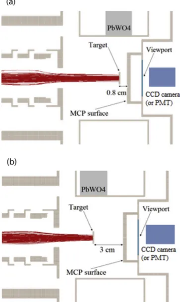
In order to characterize the behavior of the particles emitted by the target after positron implantation, three different techniques were applied. The measurement configurations can be seen in
Fig. 2:
(i) SSPALS was used to study o-Ps formation and emission from the investigated target both in transmission and reflection geometries (Fig. 2). The fraction of o-Ps formed per imping-ing positron can be estimated from the SSPALS spectrum, in which the detection of delayed gamma rays can be attribu-ted to o-Ps annihilations;
(ii) an MCP – phosphor screen assembly coupled to a CCD cam-era was employed to image forward-emitted charged parti-cles impinging on the MCP surface;
(iii) the velocity of forward-emitted charged particles was esti-mated via time-of-flight (TOF) measurements making use of an MCP – phosphor screen assembly coupled to a fast PMT.
SSPALS measurements were performed by using a PbWO4 scin-tillator (25 % 25 % 20 mm3) coupled to a Hamamatsu R11265-100 PMT. This setup was used to detect the annihilation radiation pro-duced by the intense prompt positron burst as well as from delayed o-Ps self-annihilations. The anode signal from the PMT was divided using a 50X – splitter (Mini-Circuits ZFRSC-2050B)
Fig. 1. Meso-structured porous silica imaged by SEM. For SEM-imaging, a reference sample was grown on a Si-wafer alongside the target, which was grown on a 20 nm carbon foil. The silica columns can be seen as the topmost, brighter layer in the cross-section (a), and as bright spots in the top view (b).
Fig. 2. Measurement configurations: Transmission configuration (a), in which positrons are implanted in the carbon foil (solid line), with the porous silica (dashed columns) downstream. Reflection configuration (b), in which the porous silica is facing the implanted positron bunch and the carbon foil is downstream. The forward and backward emission of Ps, positrons and secondary electrons are sketched for both configurations. The electrical scheme of the MCP assembly (not to scale) is also reported. Vsurrepresents the potential on the MCP surface, which was
varied between "800 and +200 V; the other potentials were changed accordingly, such that the potential differences were constant.
and was sent into two channels of a 1 GHz bandwidth, 12-bit oscil-loscope (Lecroy HDO6104) terminated on 50X. One channel, with a vertical scale of 2 V/div (low gain), was used to acquire the prompt peak, the other, with a scale of 200 mV/div (high gain), was used to record the long, low intensity tail of the signal in order to limit digital noise[37]. Moreover, the high frequency noise of the low gain channel was reduced using a low-pass filter with a cut-off frequency of 100 MHz. The waveforms of the two channels were recorded by a computer and automatically merged to give the SSPALS spectra. The detector was placed above the sample holder at a vertical distance of 4 cm from the target center. The relative position of target to detector was fixed in all measurements to maintain a constant solid angle of the o-Ps cloud as seen by the detector (see Fig. 3). An MCP assembly (Hamamatsu F2222-21P25 – Phosphor Screen P46) was used to characterize the spot generated by charged particles downstream of the target. The dis-tance between the MCP surface and the target was set to either 0.8 cm or 3 cm. The pulse was imaged on the phosphor screen of the MCP assembly with a CCD camera. A bias potential in the range between "800 V and +200 V was applied to the surface of the MCP to select the charge of detected particles (see electrical scheme in
Fig. 2). To ensure a constant gain, a constant voltage difference was held between the MCP surface (Vsur) and the back (Vsurþ 1400 V) and between the MCP surface and the phosphor screen (Vsurþ 4200 V). The voltage difference was kept low enough to avoid image intensity saturation. The detection efficiency of the MCP for electrons impinging perpendicularly to the surface with an energy of hundreds of eV ranges from 50% to 85%[38], while for gamma rays with an energy of the order of 511 keV it is expected to be lower than about 0.5%[39]. In the presence of a similar num-ber of electrons and gamma rays, the contribution of the latter is negligible. A SIMION#
8[40]code was used to simulate the positron transport and to verify that the focusing of positrons was not affected by changing the position of the target with respect to the MCP. The expected spot widths obtained with the target at 0.8 and 3 cm from the MCP surface are shown in Fig. 3a and b, respectively. The simulations used a positron implantation energy of 3.3 keV. No appreciable differences arise from changing the tar-get position; in both cases, the dimension of the spot is of the order of 4–5 mm FWTM.
A second PMT (Hamamatsu R11265-100), replacing the CCD camera, was placed close to the viewport facing the MCP assembly and used to detect light produced on the phosphor screen by the charges impinging on the MCP surface. The time distribution of the PMT response is given by the arrival of the emitted charged particles at the MCP. As these particles emerge from the target al-most simultaneously with the implanted positron bunch, the time distribution of the PMT signal represents a measurement of the particles’ time-of-flight distribution. Knowing this distribution and the distance the particles travel, their kinetic energy can be calculated. This measurement was performed placing the target 3 cm from the MCP surface. The MCP introduces a roughly constant signal delay, shorter than 1 ns, due to electron multiplication. The phosphor screen has a quasi-instantaneous excitation when reached by electrons produced by the MCP[38], while the decay time is of the order of hundreds of nanoseconds (10% decay time from around 100 ns up to several hundreds of ns, depending on the time distribution of the impinging particles).
3. Results and discussion 3.1. SSPALS measurements
SSPALS measurements were performed both in transmission and in reflection configurations by placing the target at 0.8 or
3 cm from the MCP surface and moving the detector position accordingly in order to keep its solid angle constant with respect to the target center. Two implantation energies were used: 3.3 keV and 4.5 keV. Positrons stop in materials according to the Makhovian distribution[41]. Assuming a density of 2 g/cm3 for the carbon layer and 0.4 g/cm3for the mesoporous silica, around 2% of positrons implanted with an energy of 3.3 keV are expected to stop in the carbon and 65% in the silica layer in transmission configuration (Fig. 2a), while the percentages are 57% in porous SiO2and 10% in C in reflection geometry (Fig. 2b). These data are reported inTable 1. The remaining positrons are not fully stopped in the target[41]; they lose only a fraction of their initial energy by scattering processes inside the target. Only a small fraction is not re-emitted: those reaching the surface with an energy lower than the positron work function of the material, i.e. around +1.5 eV for carbon[42]and around +3 eV for mesoporous silica[16].
In the SiO2structure Ps is formed either in the bulk or at the sur-face. A significant fraction of the incoming positrons is emitted from the surface as Ps, with energies ranging from approximately
Fig. 3. Simulation of positron focusing on the target performed with a SIMION#
8 code for the target at (a) 0.8 cm, and (b) 3 cm from the MCP surface. The change in the position of the PbWO4crystal to keep the solid angle between the detector and
the target constant is visualized, as well as the position of the CCD camera (or the PMT) for the imaging of forward-emitted charges (for TOF measurements).
1 to 3 eV[16]. In porous silica Ps is known to undergo diffusion in the pores and cool down as a consequence of collisions with the internal surfaces. Accordingly, Ps emitted from the porous network have significantly less energy than those emitted from the surface. From mesoporous silica targets similar to those used here, a longi-tudinal (transverse) emission energy of the order of 0.3–0.4 eV (0.2–0.3 eV) in transmission and 0.3–0.7 eV (0.2–0.4 eV) in reflec-tion has been measured[23]. Phonon-assisted emission of Ps from a graphite surface has also been observed[43]. Here, the emission is expected to occur mainly perpendicularly to the surface with an energy cutoff corresponding to the negative of the Ps work func-tion, "0.6 eV.
The fraction of incident positrons forming o-Ps can be estimated by SSPALS spectra[44]. The spectra, as shown inFig. 4, contain a prompt peak, due to very rapid annihilation of both positrons and p-Ps, followed by delayed events that correspond to long-lived o-Ps, i.e. o-Ps in-flight self-annihilation and late o-Ps pick-off annihilation. After subtraction of a background spectrum mea-sured by implanting positrons onto the MCP surface (target removed), where no Ps is formed, the fraction of delayed Ps, fd, can be calculated using the definition adopted in Ref.[23]to yield comparable results: fd¼ Z 350ns 35ns VðtÞdt ! Z 350ns "3ns VðtÞdt;
where VðtÞ is the measured detector voltage at time t. All of the sig-nal left after background subtraction (electrical noise, after-pulses of the PMT, intrinsic decay time of the crystal etc.) is due to delayed annihilations. At times longer than 35 ns after the positron implan-tation, only o-Ps can still be present and generate a signal. Based on the shot-by-shot fluctuations of the SSPALS curves, the error on all fdvalues subsequently reported in this article is estimated to be of the order of )0.007(stat))0.003(sys).
We analyze the SSPALS data with a positron implantation energy of 3.3 keV, first in the transmission configuration. When the MCP is 0.8 cm away from the target, forward-emitted Ps from the mesoporous silica structure (assuming the velocity measured for Ps in a similar target[23]) should reach the MCP surface in less than 10–20 ns, where they annihilate via pick-off. Therefore, this component cannot be distinguished from the prompt peak in the SSPALS spectrum. We find fd¼ 0:03 in this configuration; it stems from both the fraction of Ps emitted backward from the carbon layer (annihilating in vacuum) and the fraction of Ps annihilating inside the silica layer. Backward-emitted Ps can travel 5.6 cm before reaching the surface of the last electrode [26], allowing enough time for it to self-annihilate in flight and thus be recorded in the time window selected to calculate fd, adopted from Ref.[23] for comparable results.
Increasing the distance between the target and the MCP to 3 cm, also Ps emitted forward from the silica layer can annihilate in vac-uum within the selected time window. As a consequence, the fd value increases to 0.07 (seeTable 1). This value could be a slight
underestimate of the fraction of Ps, because the very fast Ps emit-ted from both sides of the target could reach the MCP or the cham-ber walls within 35 ns, which is the lower threshold of fd. This is true for Ps emitted forward (from the silica layer) with velocities higher than 3 cm
35 ns! 8:6 # 105m=s, corresponding to 4.2 eV, and for Ps emitted backward (from the carbon foil) with velocities higher than 3:4 cm
35 ns! 9:7 # 105m=s, corresponding to 5.3 eV; they do not contribute to fd. Thus, in this configuration we expect that the tion of Ps annihilating in vacuum on the carbon side plus the frac-tion annihilating inside the silica is <0.03, as less Ps emitted from the carbon self-annihilate in vacuum with respect to the result with an MCP-target distance of 0.8 cm. From the two measure-ments we can estimate, by simple subtraction, that the lower bound on the fraction of Ps emitted from the silica layer is fd¼ 0:04.
In reflection geometry, the main contribution to a Ps signal always comes from Ps annihilating in silica and from Ps emitted into vacuum from silica. More positrons stop in the carbon layer and less in the silica here with respect to the transmission
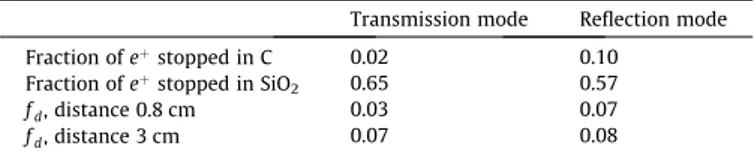
Table 1
Positron stopping fractions in the carbon and silica layers for an eþimplantation
energy of 3.3 keV, calculated according to the Makhovian distribution. The measured o-Ps delayed fraction, as defined in the text, in transmission and reflection configurations, with this implantation energy and the target placed 0.8 and 3 cm from the MCP is also reported. The error on all the reported fdvalues is of the order of
)0.007(stat))0.003(sys).
Transmission mode Reflection mode Fraction of eþstopped in C 0.02 0.10
Fraction of eþstopped in SiO2 0.65 0.57
fd, distance 0.8 cm 0.03 0.07 fd, distance 3 cm 0.07 0.08
Fig. 4. SSPALS spectra measured in transmission and reflection modes, with a distance between converter and MCP of 0.8 cm (a) and 3 cm (b). In both cases, the positron implantation energy was 3.3 keV. The SSPALS spectrum measured on the surface of the MCP, where no o-Ps is formed (background), is also reported. Each curve is the average of 35 single shots. The shot-by-shot fluctuations have been used to calculate the error on fdreported in the caption ofTable 1. The bump
configuration, which in general would lead to a lower Ps produc-tion. With the MCP at 0.8 cm, all Ps emitted from the carbon layer annihilate on the MCP within a short time, and they are thus not recorded in the selected time window. However, of the Ps emitted from the silica (which is the main fraction of created Ps), less is recorded in transmission mode than in this reflection configura-tion, as the free-flight distance is slightly smaller (3 cm versus 3.4 cm). Given these considerations, the value we find, fd¼ 0:07, is in fair agreement with that found in transmission configuration when the MCP and the target are 3 cm apart (seeTable 1). With the MCP and target 3 cm apart, a fraction of Ps emitted from the carbon film is measurable in the time window and we observe a slight increase; fd¼ 0:08.
The observed values, both in transmission and in reflection, are in reasonable agreement with the fraction of o-Ps measured via SSPALS for a similar target and positron implantation energies in an other experiment[23], where a delayed fraction fd! 0:06 and 0.08–0.09 was found for transmission and reflection configura-tions, respectively.
By increasing the positron implantation energy to 4.5 keV, the delayed Ps fraction, with the target and the MCP 3 cm apart, decreases from fd¼ 0:07 to fd¼ 0:03 in transmission mode (Fig. 5a) and from fd¼ 0:08 to fd¼ 0:04 in reflection mode (Fig. 5b). The decrease of Ps formation (by roughly a factor 2) with respect to that at 3.3 keV is due to the reduced number of positrons stopped in the target. Indeed, according to calculations based on the Makhovian profile, with an implantation energy of 4.5 keV, up to 66% of the eþare not stopped in the target (at 3.3 keV the per-centage is 33%). In reflection mode, 26% and 7% of eþstop in SiO2 and C, respectively, while in transmission mode the percentages are 33% and 1% (seeTable 2).
3.2. Imaging of charged particles
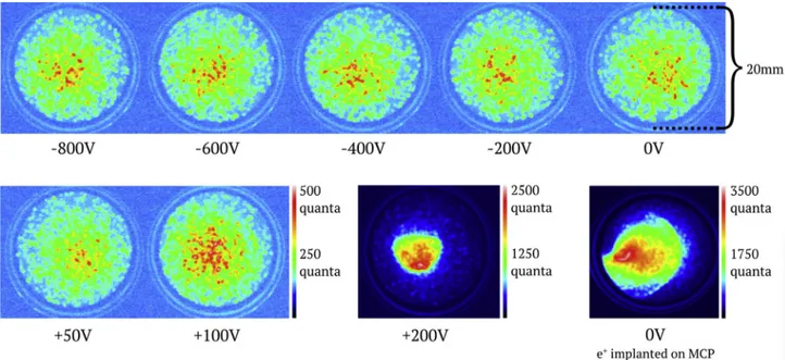
The radial distributions of positrons crossing the target and of forward-emitted electrons, produced by eþ slowing down in the material, were imaged with the MCP placed 0.8 cm downstream of the eþ/Ps converter. As shown in Refs.[45,46], the MCP is only sensitive to Ps faster than several eV, excluding the possibility of imaging slow Ps. The shape and intensity of the spot was investi-gated as a function of the MCP surface potential, varied between "800 V and +200 V, to distinguish between contributions from positrons and electrons with different energies. The scans per-formed when implanting positrons with 3.3 keV and with the tar-get in transmission and reflection configurations are reported in
Figs. 6 and 7, respectively.
In transmission mode, an intense spot was observed for poten-tials on the MCP surface higher than +100 V (Fig. 6). With a bias lower than +100 V or negative, a fainter, spread-out signal was vis-ible. No significant changes were observed when varying the potential from +50 V to "800 V.
The intense spot for positive potentials is due to forward-emitted secondary electrons produced by positrons implanted in the target. Electrons released by positron impact can be emitted into vacuum if they reach the surface before their energy becomes lower than the electron work function of the material[27,28]. In SiO2, the electron work function is quite high, 10–12 eV [16]. Therefore, only hot electrons produced in silica can overcome the surface barrier and leave the target. The emission energy of almost all these electrons is expected to range from a fraction of eV to some tens of eV; emission of secondary electrons with an energy higher than a few hundreds of eV is negligible [27,28]. As the columnar silica structure is highly irregular, the electrons have no preferred emission direction. Consequently, e" are focused on the central part of the MCP only when an attractive potential of
more than +50 V is present on its surface. At potentials between 0 and +50 V they are spread over a large solid angle and their con-tribution to the signal on the MCP is not clearly distinguishable from that of positrons (see Section3.3).
The faint image still present at lower voltages on the MCP sur-face is due to positrons crossing the target, as discussed in the pre-vious paragraph. No changes in the shape and intensity of the image can be observed when varying the bias on the MCP surface
Fig. 5. SSPALS spectra measured in transmission (a) and reflection (b) modes, with a distance between the converter and the MCP of 3 cm. Spectra obtained with a positron implantation energy of 3.3 keV and 4.5 keV are reported. The SSPALS spectrum measured on the surface of the MCP (no o-Ps formation; background) is also shown. Each curve is the average of 35 single shots. The shot-by-shot fluctuations have been used to calculate the error on fdreported in the caption of
Table 2.
Table 2
Positron stopping fractions in the carbon and silica layers, calculated according to the Makhovian distribution, for transmission and reflection configurations at an implan-tation energy of 4.5 keV. The measured o-Ps delayed fraction, fd, in transmission and
reflection configurations with this implantation energy and the target placed 3 cm from the MCP is also reported. The error on all the reported fdvalues is of the order of
)0.007(stat))0.003(sys).
Transmission mode Reflection mode Fraction of eþstopped in C 0.01 0.07
Fraction of eþstopped in SiO2 0.33 0.26
from +50 V down to "800 V. As a consequence we can deduce that positrons crossing the target are neither reflected nor deflected by this potential, therefore their energy has to be higher than 800 eV. A rough estimate of the number of positrons crossing the target and secondary electrons produced by the impact of the primary eþ bunch can be obtained by analyzing the intensity of the spot on the MCP assembly. The intensity of the spot is expected to scale lin-early with the number of particles in the case of beams reaching the MCP with the same divergence[47,48].
When around 3 " 4 # 107positrons with an energy of 3.3 keV are implanted directly onto the MCP (at 0 V bias potential, last image ofFig. 6), an integral intensity of the spot of around 27 Mquan-ta#pixel (¼ 27 # 106 photons per pixel) was observed. Implanting
the same number of positrons in the target, arranged in transmis-sion mode, with a negative potential set on the MCP surface (Fig. 6) generated a spot intensity of about 2.5 Mquanta#pixel. In both cases the images are due to positrons with an energy of the order of keV (see Section 3.3). Therefore, we estimate that at least 2:8 " 3:7 # 106 positrons reach the MCP after crossing the target in transmission mode when implanted with 3.3 keV, correspond-ing to about 10% of the implanted positrons.
According to the SIMION#
8 simulation, positrons of the primary bunch are expected to impact the MCP surface with an average angle of 5 " 10*. On the other hand, considering the dispersion in the images ofFig. 6acquired with a negative bias, it is evident that positrons scattered through the target are diffused with angles up
Fig. 6. Charged particle spot acquired with the MCP assembly as a function of the potential on the MCP surface, with a positron implantation energy of 3.3 keV and the target in transmission mode. The last image represents the positron bunch profile at 3.3 keV, transmitting positrons directly onto the MCP (no target).
Fig. 7. Charged particle spot acquired with the MCP assembly as a function of the potential on the MCP surface, with a positron implantation energy of 3.3 keV and the target in reflection configuration.
to at least 50" (given by the distance between the target and the MCP, 0.8 cm, and the dimension of the MCP, 20 mm diameter). Positrons scattered at large angles from the target and impinging on the peripheral region of the MCP are detected with lower effi-ciency with respect to positrons impacting the center of the MCP (i.e. with a low incident angle, like in the case of the primary bunch); an increase of the incident angle from 10" to 40" intro-duces a decrease of the detection efficiency of the MCP of about 30%[38]. Since we do not know the angular distribution of the scattered positrons, only a lower bound on the fraction of positrons crossing the target with a scattering angle smaller than 50" was found.
When a bias of +200 V was set on the MCP surface, electrons were attracted and focused. The intensity of the spot increased up to 9.5 Mquanta#pixel. Taking into account that the light pro-duced by a positron impinging on the MCP is around half that gen-erated by an electron with the same energy[48], the observed intensity corresponds at least to the impact of ! 5:3 " 7:0 # 106 electrons.
The presented analysis to discriminate crossing positrons from secondary electrons is confirmed by the evolution of the spot as a function of the MCP surface potential when the target is in reflec-tion configurareflec-tion (Fig. 7).
In reflection configuration, the intense spot due to secondary electrons was observed for positive potentials. The contribution due to electrons vanishes for negative voltages on the MCP surface. The reflection of electrons with a bias of "200 V is in agreement with the expected energy of secondary electrons forward-emitted from thin (5–23 nm) carbon films after 1–20 keV positron implan-tation, which is less than 100 eV as reported in Ref.[28]. Electrons emitted from the carbon side produce a spot well distinguishable from the one due to eþ, even if no attractive potential is present on the MCP surface. This was not the case for secondary electrons emitted by the mesoporous silica layer in the transmission config-uration. The observation can be ascribed to the regular structure of carbon, which allows emission of electrons closer to perpendicular to the surface than for emission from the irregular silica.
Also in reflection configuration, when the bias on the MCP is negative, the fainter, spread signal given by transmitted positrons is present and no changes were observed when varying the poten-tial between "200 and "800 V. This indicates that also in reflection geometry, the crossing positrons have an energy in excess of 800 eV.
3.3. Time-of-flight measurements of charged particles
In order to determine the kinetic energy of the charged particles emitted by the converter after positron implantation, TOF mea-surements were performed. Positrons with an energy of 3.3 keV were implanted in the target, placed 3 cm upstream of the MCP, for both transmission and reflection configurations. A third mea-surement was done by implanting positrons directly onto the MCP surface. A fast PMT coupled to the viewport facing the MCP assembly (Figs. 2 and 3) was used to detect light produced on the phosphor screen. The time distribution of the PMT signal is determined by the time of flight of the forward-emitted charged particles after positron implantation in the target. All measure-ments were carried out with 0 V on the MCP surface in order to avoid selective acceleration of particles based on their charge. The TOF measurements are shown in logarithmic scale inFig. 8, while a detail of the rising edge is displayed in linear scale in
Fig. 9. In order to compare the shapes of the curves, their peak amplitudes have been normalized.
When positrons are implanted directly onto the MCP a first peak, simultaneous with the prompt peak of the SSPALS
measurements is observed, with a rise time of around 5 ns. This first peak, produced by implanted positrons, is arbitrarily centered at t ¼ 0. A broader bump can be distinguished between 10–15 ns up to around 40–50 ns. This second structure can be interpreted as the signal generated by secondary electrons produced by the primary positron bunch hitting the MCP surface. The resulting sig-nal is convoluted with the intrinsic decay time of the phosphor flu-orescence. For the phosphor used here the 10% decay time is around 100 ns.
Both in transmission and in reflection configurations, the shapes of the spectra are similar to the one observed with direct implantation of positrons on the MCP, with a first peak due to direct positron implantation and a bump with a slow decrease due to electrons, which reach the MCP at a later time since they originate from the implanted positrons. In addition to secondary electrons produced on the MCP surface by positrons crossing the target (like in the direct positron implantation measurement), elec-trons released by eþ interaction in the target contribute to the bump.
Looking in detail at the positron peak of the transmission and reflection signals (Fig. 9), the rising edge is delayed by around 1– 2 ns with respect to direct positron implantation on the MCP. Moreover, the peak is broadened, with a full width at two-thirds maximum increasing from !8 ns (direct eþ implantation on the MCP) to !11 ns (transmission and reflection configurations). The delayed rising edge is due to the deceleration of positrons crossing the converter, while the broadening of the peak is attributable to the energy spread induced by the scattering of eþ in the target. Knowing the distance between the target and the MCP (3 cm), and the difference in the rise time of the signals, we can estimate that the fastest positrons slow down from 3.3 keV (direct eþ implantation onto the MCP) to !1.2 keV (with the target arranged both in transmission and reflection configurations).
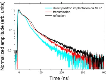
The broad bumps generated by secondary electrons are more pronounced in transmission/reflection configurations than in the case of direct eþimplantation on the MCP. This is due to electrons released from the target. The bump starts to be distinguishable from the positron peak at around 20 ns and the following tails reach the noise level only at around 300–400 ns (Fig. 8). Given the distance of 3 cm between the target and the MCP, the
Fig. 8. Time distribution of light produced on the phosphor screen by charged particles impinging on the MCP surface: as the result of one positron bunch implanted directly onto the MCP; in the target in transmission mode; in the target in reflection mode. Positrons were implanted with an energy of 3.3 keV. The target (both in reflection and in transmission configurations) was placed 3 cm from the surface of the MCP.
corresponding kinetic energy for the electrons ranges from a frac-tion of eV up to few eV (100 ns TOF corresponds to a kinetic energy of !0.3 eV, while 50 ns TOF corresponds to a kinetic energy of !1 eV), in good agreement with previous measurements per-formed by implanting eþ with an energy ranging from 1–20 keV in thin carbon foils[28].
The presence of the small peak at around 15 ns could be related to the existence of a minor secondary effect in the electron emis-sion, which will require further investigation.
3.4. Possible application of transmission targets in antihydrogen production
In the context of using transmission eþ/Ps converters for antihy-drogen production, it will be necessary to avoid interaction between the antiproton plasma, stored downstream of the target in a Penning-Malmberg trap, and the charged particles forward-emitted by the target. This may be achieved by inserting a set of grids with high transmission coefficients downstream the con-verter, very near its surface. The first grid, closest to the target, should be positively polarized in order to reflect crossing positrons directly after their re-emission. The second grid, immediately fol-lowing, should be set at a negative potential to repel secondary electrons. Moreover, this should be the same potential as on the first electrode of the trap, in order to have a region with no electric field downstream this grid. Ground state o-Ps can thus cross the two grids without being affected by the electric field and subse-quently be excited to Rydberg states in the field-free region[49].
According to the measurements reported in Sections 3.2 and 3.3, the electrons can be repelled by setting some tens of volts on the negative grid. The energy of the forward-emitted positrons is estimated to be around 1.2 keV. Thus, to efficiently reflect eþ, the positive grid should be set at a potential of the order of a couple of kV. In an ultrahigh vacuum environment, the breakdown voltage is well above this potential already for an electrode at a distance less than 1 mm[50]. Due to the short path the Ps cloud will have to travel to cross the grids, its resulting expansion is limited.
In order to estimate the geometrical overlap between the emit-ted Ps and the lasers exciting it to Rydberg states, a Monte Carlo simulation was made. Ps was assumed to be isotropically emitted from a circular region of 2 mm in diameter with a Maxwellian energy distribution of a given temperature. The lasers were shot grazing the target, as well as 2 mm away from it to simulate the space occupied by the set of grids. The laser pulses were shot after 16 ns and 28 ns in the first and the second case, respectively. Their
spot dimension was assumed to be 6 mm in the vertical direction and 4 mm in the horizontal one (corresponding to the FWHMs of the main laser in Ref.[26]). If the average temperature of the emit-ted Ps is around 1300 K (as measured in reflection targets[26]), the geometrical overlap between the Ps cloud and the laser beams is reduced by about a factor 2.8 for the case the laser beams are shifted by 2 mm downstream with respect to the target-grazing case (Fig. 10a). This reduction in the overlap can be mitigated by decreasing the dimension of the Ps source or by increasing the transversal dimension of the laser spot (Fig. 10b). An increase of the beam waist by some tens of percent is possible without reduc-ing the excitation efficiency when the considered transition is sat-urated or near saturation, like in Ref.[26].
If the average temperature of Ps is !6000 K (as in transmission targets similar to the one used here[23]), the fraction of geometri-cally addressable Ps is around 2.7 times that of the 2 mm-scenario when the laser beams graze the target surface (Fig. 10c). Also in this case, the increase of the beam waist can help address a larger fraction of Ps (Fig. 10d).
While the necessity of the grids to repel forward-emitted charged particles is expected to reduce the number of Ps in Ryd-berg states by approximately a factor two, the possibility to place the target closer to the antiproton plasma would largely compen-sate for this. Indeed, from the considerations above, in transmis-sion configuration, the target can be placed at a distance less than 1 cm from the antiproton cloud. This is a considerable reduc-tion with respect to the !2 cm achievable in the reflecreduc-tion config-uration [7], assuring an increase of the geometrical overlap between excited Ps and the antiproton plasma up to a factor 4. Thus, if transmission targets with Ps emission and cooling efficien-cies similar to the ones of present reflection targets will be devel-oped, this will be a direct gain. An additional advantage could come from the shape of the antiproton plasma that is typically an oblate, with the dimension transversal to the trap axis smaller than the longitudinal one. This supports a larger overlap between the Ps and the antiprotons in the transmission configuration, as more of the Ps traverses the plasma along the major axis, while in reflection configuration most of the Ps traverses the cloud along the minor axis.
4. Conclusion
In the presented work, a transmission positron/positronium converter composed by thin, ultraporous, meso-structured silica deposited on a 20 nm carbon foil was characterized. The emission of o-Ps both in transmission and in reflection was confirmed via SSPALS measurements. The amount of delayed o-Ps was found to be in agreement with previous work on similar targets[23]. This is consistent with a maximum o-Ps formation fraction in transmis-sion of around 10%, as estimated for similar targets in other works
[22,23].
Charged particles forward-emitted by the converter were imaged using an MCP – phosphor assembly coupled to a CCD cam-era placed behind the target. A bias potential ranging from "800 up to +200 V was set on the MCP surface to distinguish crossing positrons from secondary electrons. The kinetic energy of these charged particles was estimated by detecting the light produced on the phosphor screen due to charged particles impinging on the MCP surface with a fast PMT. A lower bound of !10% for the fraction of positrons, implanted with an energy of 3.3 keV, able to cross the target and be forward-emitted with a scattering angle smaller than 50", was found. The maximum kinetic energy of this crossing fraction was estimated to be !1.2 keV. The presence of such a fast component can be explained by a large fraction of positrons crossing the target after experiencing a limited number
of scatterings in the carbon layer and the silica structure, thus los-ing just a small fraction of their energy. Furthermore, as a result of around 3 " 4 # 107 positrons implanted in the target, at least 5 " 7 # 106 secondary electrons were forward-emitted with a kinetic energy of the order of an electronvolt. Reducing the posi-tron implantation energy is expected to slightly decrease the amount of fast crossing positrons and secondary electrons, but
their presence cannot be completely avoided, due to the modest thickness of the carbon foil as well as the mesoporous structure of the silica layer[28].
In the context of using transmission eþ/Ps converters for antihy-drogen production, it is necessary to avoid interaction between charged particles forward-emitted by the target and the antiproton plasma; this could be achieved by using a set of polarized grids
Fig. 10. Monte Carlo simulation of the geometrical overlap between Ps atoms emitted by the target and laser beams for Rydberg excitation. Red (blue) spots represent Ps atoms that are addressable by target-grazing lasers (2 mm-distant lasers) for an average Ps temperature of 1300 K (a and b) and 6000 K (c and d). The enhancement of the geometrical overlap given by the increase of the laser spot in the vertical direction by 50 % is shown in (b) and (d). The ratios of the geometrical overlaps of the scenarios target-grazing lasers and 2 mm-distant lasers are also reported for the different configurations.
with high transmission coefficients, placed downstream of the converter.
A first study of a transmission eþ/Ps converter for the applica-tion of antihydrogen producapplica-tion has been successfully carried out. Thanks to the mentioned credible advantages of the transmis-sion configuration over the reflection configuration, the reported results are promising for the possibility to apply such targets to antihydrogen production in the future. However, the amount of cold positronium available for the charge-exchange reaction is key for antihydrogen production, and more developments will be necessary to reach the present efficiency, both in terms of positro-nium production and cooling, of reflection targets. There is room for improvements in this direction by changes in the structure of the meso-porous silica and the thickness of the carbon foil. A study of the positronium resulting from transmission targets grown with different parameters remains to be done. Work in this direction is planned, involving both converter development and alterations to the experimental setup in order to facilitate such measurements. Acknowledgments
This work was supported by the Swiss National Science Founda-tion Ambizione Grant (No. 154833); Istituto Nazionale di Fisica Nucleare; a Deutsche Forschungsgemeinschaft research grant; an excellence initiative of Heidelberg University; European Research Council under the European Union’s Seventh Framework Program FP7/2007-2013 (Grants Nos. 291242 and 277762); Austrian Min-istry for Science, Research, and Economy; Research Council of Nor-way; Bergen Research Foundation; John Templeton Foundation; Ministry of Education and Science of the Russian Federation and Russian Academy of Sciences; and the European Social Fund within the framework of realizing the project, in support of intersectoral mobility and quality enhancement of research teams at Czech Technical University in Prague (Grant No. CZ.1.07/2.3.00/30.0034). References
[1] M. Deutsch, Evidence for the formation of positronium in gases, Phys. Rev. 82 (1951) 455–456,http://dx.doi.org/10.1103/PhysRev. 82.455.
[2] S. Berko, H.N. Pendleton, Positronium, Ann. Rev. Nucl. Part. Sci. 30 (1980) 543– 581,http://dx.doi.org/10.1146/annurev.ns.30.120180.002551.
[3] S.G. Karshenboim, Precision study of positronium: testing bound state qed theory, Int. J. Mod. Phys. A 19 (23) (2004) 3879–3896, http://dx.doi.org/ 10.1142/S0217751X04020142.
[4] N. Prantzos, C. Boehm, A.M. Bykov, R. Diehl, K. Ferrière, N. Guessoum, P. Jean, J. Knoedlseder, A. Marcowith, I.V. Moskalenko, A. Strong, G. Weidenspointner, The 511 keV emission from positron annihilation in the galaxy, Rev. Mod. Phys. 83 (2011) 1001–1056,http://dx.doi.org/10.1103/RevModPhys. 83.1001. [5] D.W. Gidley, H.G. Peng, R.S. Vallery, Positron annihilation as a method to
characterize porous materials, Annu. Rev. Mater. Res. 36 (1) (2006) 49–79,
http://dx.doi.org/10.1146/annurev.matsci.36.111904.135144.
[6] M. Charlton, Antihydrogen production in collisions of antiprotons with excited states of positronium, Phys. Lett. A 143 (3) (1990) 143–146,http://dx.doi.org/ 10.1016/0375-9601(90)90665-B.
[7] M. Doser, C. Amsler, A. Belov, G. Bonomi, P. Bräunig, J. Bremer, R. Brusa, G. Burkhart, L. Cabaret, C. Canali, F. Castelli, K. Chlouba, S. Cialdi, D. Comparat, G. Consolati, L.D. Noto, A. Donzella, A. Dudarev, T. Eisel, R. Ferragut, G. Ferrari, A. Fontana, P. Genova, M. Giammarchi, A. Gligorova, S. Gninenko, S. Haider, J.P. Hansen, S. Hogan, L. Jorgensen, T. Kaltenbacher, A. Kellerbauer, D. Krasnicky, V. Lagomarsino, S. Mariazzi, V. Matveev, F. Merkt, F. Moia, G. Nebbia, P. Nedelec, M. Oberthaler, D. Perini, V. Petracek, F. Prelz, M. Prevedelli, C. Regenfus, C. Riccardi, O. Rohne, A. Rotondi, M. Sacerdoti, H. Sandaker, M. Spacek, J. Storey, G. Testera, A. Tokareva, D. Trezzi, R. Vaccarone, F. Villa, Z. Zavatarelli, A. Zenoni, A. Collaboration, Exploring the wep with a pulsed cold beam of antihydrogen, Class. Quantum Gravity 29 (18) (2012) 184009,http://dx.doi.org/10.1088/ 0264-9381/29/18/184009.
[8] D. Krasnicky´, R. Caravita, C. Canali, G. Testera, Cross section for Rydberg antihydrogen production via charge exchange between Rydberg positroniums and antiprotons in a magnetic field, Phys. Rev. A 94 (2016) 022714,http://dx. doi.org/10.1103/PhysRevA.94.022714.
[9] A.P. Mills Jr., M. Leventhal, Can we measure the gravitational free fall of cold Rydberg state positronium?, Nucl Instrum. Methods Phys. Res., Sect. B 192 (1– 2) (2002) 102–106,http://dx.doi.org/10.1016/S0168-583X(02)00789-9.
[10] D.B. Cassidy, S.D. Hogan, Atom control and gravity measurements using Rydberg positronium, Int. J. Mod. Phys.: Conf. Ser. 30 (2014) 1460259,http:// dx.doi.org/10.1142/S2010194514602592.
[11] P.M. Platzman, A.P. Mills, Possibilities for Bose condensation of positronium, Phys. Rev. B 49 (1994) 454–458,http://dx.doi.org/10.1103/PhysRevB.49.454. [12] D.B. Cassidy, A.P. Mills, The production of molecular positronium, Nature 449
(2007) 195–197,http://dx.doi.org/10.1038/nature06094.
[13]A.P. Mills, Positron Solid State Physics, Experiments with low-energy positron beams, in: W. Brandt, A. Dupasquier (Eds.), Amsterdam, North-Holland, 1983, pp. 432–509.
[14]K.G. Lynn, Positron Solid State Physics, Slow positrons in the study of surface and near-surface defects, in: W. Brandt, A. Dupasquier (Eds.), Amsterdam, North-Holland, 1983, pp. 609–643.
[15] P.J. Schultz, K.G. Lynn, Interaction of positron beams with surfaces, thin films, and interfaces, Rev. Mod. Phys. 60 (1988) 701–779,http://dx.doi.org/10.1103/ RevModPhys. 60.701.
[16] Y. Nagashima, Y. Morinaka, T. Kurihara, Y. Nagai, T. Hyodo, T. Shidara, K. Nakahara, Origins of positronium emitted from SiO2, Phys. Rev. B 58 (1998)
12676–12679,http://dx.doi.org/10.1103/PhysRevB.58.12676.
[17] C. He, T. Ohdaira, N. Oshima, M. Muramatsu, A. Kinomura, R. Suzuki, T. Oka, Y. Kobayashi, Evidence for pore surface dependent positronium thermalization in mesoporous silica/hybrid silica films, Phys. Rev. B 75 (2007) 195404,http://dx. doi.org/10.1103/PhysRevB.75.195404.
[18] S. Mariazzi, P. Bettotti, S. Larcheri, L. Toniutti, R.S. Brusa, High positronium yield and emission into the vacuum from oxidized tunable nanochannels in silicon, Phys. Rev. B 81 (2010) 235418, http://dx.doi.org/10.1103/ PhysRevB.81.235418.
[19] D.B. Cassidy, P. Crivelli, T.H. Hisakado, L. Liszkay, V.E. Meligne, P. Perez, H.W.K. Tom, A.P. Mills, Positronium cooling in porous silica measured via Doppler spectroscopy, Phys. Rev. A 81 (2010) 012715, http://dx.doi.org/10.1103/ PhysRevA.81.012715.
[20] S. Mariazzi, P. Bettotti, R.S. Brusa, Positronium cooling and emission in vacuum from nanochannels at cryogenic temperature, Phys. Rev. Lett. 104 (2010) 243401,http://dx.doi.org/10.1103/PhysRevLett. 104.243401.
[21] L. Liszkay, F. Guillemot, C. Corbel, J.-P. Boilot, T. Gacoin, E. Barthel, P. Pérez, M.-F. Barthe, P. Desgardin, P. Crivelli, U. Gendotti, A. Rubbia, Positron annihilation in latex-templated macroporous silica films: pore size and ortho-positronium escape, New J. Phys. 14 (6) (2012) 065009, http://dx.doi.org/10.1088/1367-2630/14/6/ 065009.
[22] S.L. Andersen, R.R. Johansen, J.B. Overgaard, J.K. Mortensen, K.K. Andersen, H.D. Thomsen, M.D. Lund, J. Chevallier, H. Knudsen, U.I. Uggerhj, Positronium formation from porous silica in backscattering and transmission geometries, Eur. Phys. J. D 68 (5) (2014) 124, http://dx.doi.org/10.1140/epjd/e2014-40762-x.
[23] S.L. Andersen, D.B. Cassidy, J. Chevallier, B.S. Cooper, A. Deller, T.E. Wall, U.I. Uggerhj, Positronium emission and cooling in reflection and transmission from thin meso-structured silica films, J. Phys. B: At. Mol. Opt. Phys. 48 (20) (2015) 204003,http://dx.doi.org/10.1088/0953-4075/48/20/204003.
[24] S.L. Andersen, Positronium Formation & Cooling in Meso-Structured Silica Films (Ph.D. thesis), Aarhus University, Department of Physics and Astronomy, Ny Munkegade 120, 8000 Aarhus C, Denmark (March 2015). URLhttp://pure. au.dk/portal/files/90669596/thesisSLAndersen.pdf.
[25] D.B. Cassidy, T.H. Hisakado, H.W.K. Tom, A.P. Mills, Efficient production of Rydberg positronium, Phys. Rev. Lett. 108 (2012) 043401,http://dx.doi.org/ 10.1103/PhysRevLett. 108.043401.
[26] S. Aghion, C. Amsler, A. Ariga, T. Ariga, G. Bonomi, P. Bräunig, J. Bremer, R.S. Brusa, L. Cabaret, M. Caccia, R. Caravita, F. Castelli, G. Cerchiari, K. Chlouba, S. Cialdi, D. Comparat, G. Consolati, A. Demetrio, L. Di Noto, M. Doser, A. Dudarev, A. Ereditato, C. Evans, R. Ferragut, J. Fesel, A. Fontana, O.K. Forslund, S. Gerber, M. Giammarchi, A. Gligorova, S. Gninenko, F. Guatieri, S. Haider, H. Holmestad, T. Huse, I.L. Jernelv, E. Jordan, A. Kellerbauer, M. Kimura, T. Koettig, D. Krasnicky, V. Lagomarsino, P. Lansonneur, P. Lebrun, S. Lehner, J. Liberadzka, C. Malbrunot, S. Mariazzi, L. Marx, V. Matveev, Z. Mazzotta, G. Nebbia, P. Nedelec, M. Oberthaler, N. Pacifico, D. Pagano, L. Penasa, V. Petracek, C. Pistillo, F. Prelz, M. Prevedelli, L. Ravelli, L. Resch, B. Rienäcker, O.M. Røhne, A. Rotondi, M. Sacerdoti, H. Sandaker, R. Santoro, P. Scampoli, L. Smestad, F. Sorrentino, M. Spacek, J. Storey, I.M. Strojek, G. Testera, I. Tietje, S. Vamosi, E. Widmann, P. Yzombard, J. Zmeskal, N. Zurlo, Laser excitation of the n ¼ 3 level of positronium for antihydrogen production, Phys. Rev. A 94 (2016) 012507,
http://dx.doi.org/10.1103/PhysRevA.94.012507.
[27] R. Mayer, A. Weiss, Comparative study of secondary-electron emission from positron and electron bombardment of Ni, Si, and MgO, Phys. Rev. B 38 (1988) 11927–11930,http://dx.doi.org/10.1103/PhysRevB.38.11927.
[28] B. Yang, L. Cai, C. Ng, C. Ling, S. Fung, Thickness dependence of positron induced secondary electron emission in forward geometry from thin carbon foils, Nucl. Instrum. Methods Phys. Res., Sect. B 269 (13) (2011) 1523–1526,
http://dx.doi.org/10.1016/j.nimb.2011.04.107.
[29] J. Weiner, V.S. Bagnato, S. Zilio, P.S. Julienne, Experiments and theory in cold and ultracold collisions, Rev. Mod. Phys. 71 (1999) 1–85,http://dx.doi.org/ 10.1103/RevModPhys. 71.1.
[30] D.B. Cassidy, A.P. Mills Jr., A fast detector for single-shot positron annihilation lifetime spectroscopy, Nucl. Instrum. Methods Phys. Res., Sect. A 580 (3) (2007) 1338–1343,http://dx.doi.org/10.1016/j.nima.2007.06.078.
[31] S. Aghion, C. Amsler, A. Ariga, T. Ariga, A. Belov, G. Bonomi, P. Bräunig, J. Bremer, R. Brusa, L. Cabaret, M. Caccia, R. Caravita, F. Castelli, G. Cerchiari, K. Chlouba, S. Cialdi, D. Comparat, G. Consolati, A. Demetrio, L.D. Noto, M. Doser,
A. Dudarev, A. Ereditato, C. Evans, J. Fesel, A. Fontana, O. Forslund, S. Gerber, M. Giammarchi, A. Gligorova, S. Gninenko, F. Guatieri, S. Haider, H. Holmestad, T. Huse, I. Jernelv, E. Jordan, T. Kaltenbacher, A. Kellerbauer, M. Kimura, T. Koetting, D. Krasnicky, V. Lagomarsino, P. Lebrun, P. Lansonneur, S. Lehner, J. Liberadzka, C. Malbrunot, S. Mariazzi, L. Marx, V. Matveev, Z. Mazzotta, G. Nebbia, P. Nedelec, M. Oberthaler, N. Pacifico, D. Pagano, L. Penasa, V. Petracek, C. Pistillo, F. Prelz, M. Prevedelli, L. Ravelli, B. Rienäcker, O. Røhne, S. Rosenberger, A. Rotondi, M. Sacerdoti, H. Sandaker, R. Santoro, P. Scampoli, F. Sorrentino, M. Spacek, J. Storey, I. Strojek, G. Testera, I. Tietje, S. Vamosi, E. Widmann, P. Yzombard, S. Zavatarelli, J. Zmeskal, Positron bunching and electrostatic transport system for the production and emission of dense positronium clouds into vacuum, Nucl. Instrum. Methods Phys. Res., Sect. B 362 (2015) 86–92,http://dx.doi.org/10.1016/j.nimb.2015.08.097.
[32] L. Penasa, L.D. Noto, M. Bettonte, S. Mariazzi, G. Nebbia, R.S. Brusa, Positron bunching system for producing positronium clouds into vacuum, J. Phys: Conf. Ser. 505 (1) (2014) 012031, http://dx.doi.org/10.1088/1742-6596/505/1/ 012031.
[33] A.P. Mills, E.M. Gullikson, Solid neon moderator for producing slow positrons, Appl. Phys. Lett. 49 (17) (1986) 1121–1123, http://dx.doi.org/10.1063/ 1.97441.
[34] J.R. Danielson, D.H.E. Dubin, R.G. Greaves, C.M. Surko, Plasma and trap-based techniques for science with positrons, Rev. Mod. Phys. 87 (2015) 247–306,
http://dx.doi.org/10.1103/RevModPhys. 87.247.
[35] R.G. Greaves, C.M. Surko, Inward transport and compression of a positron plasma by a rotating electric field, Phys. Rev. Lett. 85 (2000) 1883–1886,
http://dx.doi.org/10.1103/PhysRevLett. 85.1883.
[36] K. Robbie, L.J. Friedrich, S.K. Dew, T. Smy, M.J. Brett, Fabrication of thin films with highly porous microstructures, J. Vac. Sci. Technol. A 13 (3) (1995) 1032– 1035,http://dx.doi.org/10.1116/1.579579.
[37] D.B. Cassidy, S.H.M. Deng, H.K.M. Tanaka, A.P. Mills, Single shot positron annihilation lifetime spectroscopy, Appl. Phys. Lett. 88 (19) (2006) 194105,
http://dx.doi.org/10.1063/1.2203336.
[38] MCP assembly, technical information. http://www.triumf.ca/sites/ default/files/Hamamatsu%20MCP%20guide.pdf.
[39] Y.T. Tanaka, I. Yoshikawa, K. Yoshioka, T. Terasawa, Y. Saito, T. Mukai, Gamma-ray detection efficiency of the microchannel plate installed as an ion detector in the low energy particle instrument onboard the geotail satellite, Rev. Sci. Instrum. 78 (3) (2007) 034501,http://dx.doi.org/10.1063/1.2713440.
[40] Scientific Instrument Services (SIS), Simion URLhttp://simion.com. [41] S. Valkealahti, R.M. Nieminen, Monte carlo calculations of keV electron and
positron slowing down in solids. ii, Appl. Phys. A 35 (1) (1984) 51–59,http:// dx.doi.org/10.1007/BF00620300.
[42] E.M. Gullikson, A.P. Mills, Bragg reflection of low-energy positrons from the surface of graphite, Phys. Rev. B 36 (1987) 8777–8779,http://dx.doi.org/ 10.1103/PhysRevB.36.8777.
[43] P. Sferlazzo, S. Berko, K.G. Lynn, A.P. Mills, L.O. Roellig, A.J. Viescas, R.N. West, Evidence for phonon-assisted positronium emission from graphite, Phys. Rev. Lett. 60 (1988) 538–541,http://dx.doi.org/10.1103/PhysRevLett. 60.538. [44] D.B. Cassidy, T.H. Hisakado, H.W.K. Tom, A.P. Mills, Positronium formation via
excitonlike states on Si and Ge surfaces, Phys. Rev. B 84 (2011) 195312,http:// dx.doi.org/10.1103/PhysRevB.84.195312.
[45] A.P. Mills, W.S. Crane, Beam-foil production of fast positronium, Phys. Rev. A 31 (1985) 593–597,http://dx.doi.org/10.1103/PhysRevA.31.593.
[46] D.W. Gidley, R. Mayer, W.E. Frieze, K.G. Lynn, Glancing angle scattering and neutralization of a positron beam at metal surfaces, Phys. Rev. Lett. 58 (1987) 595–598,http://dx.doi.org/10.1103/PhysRevLett. 58.595.
[47] Photomultiplier tubes, Basics and Applications, third edition, 2007 Hamamatsu Photonics K. K, Chapter 10.
[48] G.B. Andresen, W. Bertsche, P.D. Bowe, C.C. Bray, E. Butler, C.L. Cesar, S. Chapman, M. Charlton, S.S.E. Nasr, J. Fajans, M.C. Fujiwara, D.R. Gill, J.S. Hangst, W.N. Hardy, R.S. Hayano, M.E. Hayden, A.J. Humphries, R. Hydomako, L.V. Jrgensen, S.J. Kerrigan, L. Kurchaninov, R. Lambo, N. Madsen, P. Nolan, K. Olchanski, A. Olin, A.P. Povilus, P. Pusa, E. Sarid, D.M. Silveira, J.W. Storey, R.I. Thompson, D.P. van der Werf, Y. Yamazaki, ALPHA Collaboration, Antiproton, positron, and electron imaging with a microchannel plate/phosphor detector, Rev. Sci. Instrum. 80 (12) (2009) 123701,http://dx.doi.org/10.1063/1.3266967. [49] In order to efficiently repel positrons crossing the target, electric fields of the order of thousands of V/cm should be applied. Rydberg Ps could be field-ionized in such an environment. For instance, a field of 2000 V/cm would be enough to field-ionize Rydberg o-Ps with principal quantum number n higher than 17 [see F. Castelli, I. Boscolo, S. Cialdi, M.G. Giammarchi, D. Comparat, Efficient positronium laser excitation for antihydrogen production in a magnetic field, Phys. Rev. A 78 (2008) 052512. doi:10.1103/ PhysRevA.78.052512.].
[50] M.J. Mulchany, P. Bolin, High voltage breakdown study, Handbook of vacuum insulation, 1971.