1
ALMA MATER STUDIORUM
UNIVERSITA’ DI BOLOGNA
SCUOLA DI INGEGNERIA E ARCHITETTURA
Sede di Forlì
Corso di Laurea in
INGEGNERIA AEROSPAZIALE
Classe LM-20
TESI DI LAUREA
in Strutture Aeronautiche
Analytical model for the prediction of
wrinkling of rear pressure bulkheads
CANDIDATO RELATORE
Alberto Ferrari Prof. Enrico Troiani
Anno Accademico 2013/2014
Sessione III
3
Abstract
______________________________________________________________________
In Airbus GmbH (Hamburg) has been developed a new design of Rear Pressure Bulkhead (RPB) for the A320-family. The new model has been formed with vacuum forming technology. During this process the wrinkling phenomenon occurs. In this thesis is described an analytical model for prediction of wrinkling based on the energetic method of Timoshenko. Large deflection theory has been used for analyze two cases of study: a simply supported circular thin plate stamped by a spherical punch and a simply supported circular thin plate formed with vacuum forming technique. If the edges are free to displace radially, thin plates will develop radial wrinkles near the edge at a central deflection approximately equal to four plate thicknesses 𝑤ℎ0 ≈ 4 if they’re stamped by a spherical punch and 𝑤ℎ0 ≈ 3 if they’re formed with vacuum forming technique. Initially, there are four symmetrical wrinkles, but the number increases if the central deflection is increased. By using experimental results, the “Snaptrhough” phenomenon is described.
5
Contents
_____________________________________________________________________________
Abstract ... 3
1. Introduction ... 7
2. Creep age forming ... 9
3. The wrinkling phenomenon ... 11
3.1 The bifurcation method ... 16
3.2 The energy method ... 17
4. The case study ... 19
4.1 Wrinkling of a circular elastic plate stamped by a spherical punch ... 19
4.2 Wrinkling of a circular elastic plate using vacuum forming... 30
5. Discussion of results ... 35
5.1 Experimental results ... 38
6. Conclusions ... 43
7
1
.
Introduction
______________________________________________________________________
Safety and weight are one of the most important aspects in an aircraft. Designers are led to using thin structural components for make them lighter. The structural behavior of thin plates or membranes has always attracted considerable attention.
Airbus, a leading aircraft manufacturer, wanted to modify the Rear Pressure Bulkhead of the A320 family with a new manufacturing process.
Actually, the RPB, is made out of four riveted stretched formed Al alloy sheets. The new configuration is going to be made out of a single thin sheet of metal formed by using a Creep age forming technique.
Airbus noticed that during the forming process occurs one of the major defects in sheet metal forming: the wrinkling phenomenon. A circular elastic plate with this phenomenon is absolutely unusable for any purpose. The ability to predict the occurrence of wrinkling is critical to the design of tooling and processing parameters. It is possible to predict the wrinkling behavior by using three different methods: the bifurcation method, the energy equilibrium method (both analytical) and with the aid of finite element method.
In this thesis is developed an analytical model for prediction of wrinkling by using a Timoshenko’s energy method. The next chapters will be mainly discuss about this phenomenon, explaining all the previous important studies with a detailed literature review.
Two cases of study are developed:
- Wrinkling of a circular elastic plate stamped by a spherical punch - Wrinkling of a circular elastic plate using vacuum forming
In addition tests at different temperatures were studied, combining vacuum forming and ageing forming techniques. All the results are discussed in the last chapter, defining new cases of study and new important tests that should be done.
9
2
.
Creep age forming
______________________________________________________________________
Creep age forming is used for several decades in different areas under various conditions. It is a combination of vacuum forming with ageing on an alloy in an autoclave. It is used usually for aluminum machined plates. Figure 2.1 shows the three stages. As vacuum forming, creep age forming use vacuum between the plate and the tool. Autoclave pressure is raised up and when the specimen is in contact with the negative mold (stage 1) heat is applied. Extra pressure can be imposed during the stage 2. During the second stage, both of the temperature and pressure are optimized for the ageing process. As can be seen from the figure below, at the end of the process (stage 3) spring-back occurs since the temperature used for ageing is not high enough to allow a high enough stress relaxation. The interruption of the creep process due to ageing restriction leads to spring-backs in the order of 70%. Creep age forming is successfully used by different aircraft manufacturers in a wide range of applications. In order to be able to form a panel by creeping, a load has to be applied at a temperature higher than about 30% of the material melting temperature.
Figure 2.1 – Creep age forming process stages [33]
The first aircraft to receive creep age forming parts was the USAF B-1B Long Range Combat Aircraft. Both the upper and lower wing skins were manufactured using CAF. Gulfstream G-IV project marks the first time a double curvature wind panel was made using CAF techniques [33].
Airbus used CAF on Airbus 330 and 340 imparting twist and curvature to extruded stringers [34].
10
11
3
.
The wrinkling phenomenon
____________________________________________________________________________
Wrinkling is a form of compressive instability, which usually occurs in a flange with a free edge [1]. It is a unwanted phenomenon in sheet metal forming, especially when it occurs on the edge of final part. It is a complex local phenomenon, which depends on local curvatures, sheet thickness, material properties and stress state [2]. Additionally it depends on the tooling used for forming and the corresponding degrees of freedom. Large wrinkles may damage dies, for these reasons the prediction and prevention of this phenomenon is really significant. For simple geometries and using several simplifications, the critical wrinkling stress may be defined. It is however possible to say, that among others a decrease in the ratio of the thickness to radius of curvature decreases the critical wrinkling stress and therefore increases the likelihood of wrinkling. Furthermore, wrinkling seems to depend more strongly on geometrical factors than on the material itself [1]. This phenomenon can be partially avoided by using a blank holder as it shows in Figure 3.1
12
Figure 3.2 – Sertom P2MF 200x4 press [29]
This method is called “deep drawing”. The sheet is pressed by a punch (Figure 3.2) while it is fixed under the blank holder. This method is shown in Figure 3.3 and Figure 3.4. Consequently, compressive hoop stress can be developed on the side of the wall or under the holder: this may cause wrinkling.
13
Based on deep drawing modelling and experiments, a high clamping force could prevent or at least reduce wrinkling [22]. Due to the high forces involved, it does not seem to be feasible to rely on a reinforced sheet, but the tooling concept has to foresee a significant clamping system and probably enough excess material to allow proper clamping.
Figure 3.4 – Deep drawing process [31]
The compressive stress for initiate a side-wall wrinkle is smaller than the one for initiate a flange wrinkle. For this reason, a side-wall wrinkle is easier to be formed and then, this phenomenon, has greater industrial importance and interest.
Sheet metal wrinkling is described as being linearly dependent on the thickness and to the square root of the hardening parameter [24]. The same author shows finite element method mesh refinement based on a wrinkling criteria and the influence of the blank holder force on wrinkling. It is shown, that if the sheet is not heavily clamped, wrinkling occurs. The same observation is also made by other authors [25].
A number of researches were performed in order to minimize errors in the final product. Flange (Figure 3.5) wrinkling has been solved in various studies [3-6] especially in Tomita [7] and Esche [8] ones.
14
Figure 3.5 – Flange wrinkles during deep drawing [28]
Even if the analytical solution can be achieved in an almost negligible computational time, a lot of studies focused on solving simple problems like a circular ring under inward tension, annular plate under bending with a conical punch at the center.
Plastic bifurcation analysis is one of the most widely used approaches to predict the onset of wrinkling. Hutchinson and Neale [2] and Neale and Tugcu [9] studied this phenomenon where Donnell-Mushtari-Vlasov (DMV) plate shell theory were used.
Since the application was applicable to the regions of the sheet which are free of contact, Tugcu [10,11] extended their approach with a flat plate of infinite curvatures. All of these analyses are limited to long wavelength shallow mode avoiding all the boundary conditions along the edge.
A similar approach was used by Wang [12] applying a criterion to axisymmetric shrink flanging.
Triantafyllidis and Needleman [13] studied this problem by considering the binder as an elastic foundation, analyzing its effect on critical buckling and number of waves.
Fatnassi [14] investigated the effect of geometry and material properties on the onset of non-axisymmetric plastic instability, connecting the buckling point determined by Hill’s bifurcation theory and a non-axisymmetric buckling mode.
Another approach to analytically investigate the wrinkling/buckling problem is the energy method. This method will be discussed in the next chapters for solving the
15
prediction model of wrinkling in this thesis. Senior [16], Yu and Johnson [17], Cao and Boyce [3], Wang and Cao [5] and Cao and Wang [6] .
The second main approach is to predict the wrinkling behavior by using he numerical simulations and experiments. Providing a reference of the wrinkling-resistant properties, Yoshida [18] developed a simple test by studying cup forming processes. Tomita and Shindo [19] studied analytically and numerically the effects of the material properties in Yoshida tests.
FEM simulations studies has been done. This approach for predict the wrinkling is very efficient but it’s also very complicated since it need to set boundary conditions. Moreover, it’s difficult to predict a wrinkling phenomenon if the material is without initial imperfections. It is very sensitive to the input parameters (element type, mesh density etc.).
Mackerle presented exhaustive bibliography in [20] about the FEM. He focused on material properties, fracture mechanics, bending, pressing, deep drawing etc.
Ambrogio et al. in [21] focused on material formability and on the evaluation and compensation of elastic springback.
Wang, Cao and Li in [22] applied bending on a thin walled product edges. The result of their study is that the thickness has no influence on the number of wrinkles.
As written before, there are two main analytical methods for predict the wrinkles: the bifurcation analysis and the energy method.
16
3.1 The bifurcation method
With the bifurcation analysis is possible to determine the critical wrinkling stress as shown in the equations below [27,28,32].
Figure 3.1.1 – Double-curved surface [27]
𝜎1𝑐𝑟 = 1 √3 𝑡 𝑅22√2𝐿211( 𝑅2 𝑅1) 2 + 3𝐿11𝐿22+ 4𝐿11𝐿12(𝑅2 𝑅1) − 𝐿212 𝐿11= 𝐿̅1111= 4 3𝐸̅ − (𝐸̅ − 𝐸𝑡) ( 𝜎1 𝜎𝑒) 2 ̅̅̅̅̅̅̅̅̅̅̅̅̅̅̅̅̅̅̅̅̅̅̅̅̅̅̅̅̅̅̅̅̅̅̅̅̅ 𝐿22= 𝐿̅2222 =4 3𝐸̅ − (𝐸̅ − 𝐸𝑡) ( 𝜎2 𝜎𝑒) 2 ̅̅̅̅̅̅̅̅̅̅̅̅̅̅̅̅̅̅̅̅̅̅̅̅̅̅̅̅̅̅̅̅̅̅̅̅̅ 𝐿12 = 𝐿̅1122 = 2 3𝐸̅ − (𝐸̅ − 𝐸𝑡) ( 𝜎1𝜎2 𝜎𝑒2 ) ̅̅̅̅̅̅̅̅̅̅̅̅̅̅̅̅̅̅̅̅̅̅̅̅̅̅̅̅̅̅̅̅̅̅̅̅̅̅ 𝜎𝑒= √𝜎12− 𝜎 1𝜎2+ 𝜎22
For surfaces without contact the critical stress may be expressed in a simplified way as shown below. This is probably more realistic for the creep forming process, where a vacuum load gradually increases the radius of curvature.
𝜎1𝑐𝑟 =
1 √3
𝑡
17
Where:
- t is the sheet thickness
- 𝑅1 and 𝑅2 are the radii of curvature as shown in Figure 3.1.1
- 𝐿𝑖𝑗 are the plane stress incremental, which generally depend on the stresses
themselves. These values may be found in literature [28] - 𝜎𝑒 is the effective stress
- 𝐸𝑡 is the tangent modulus (slope of the uniaxial strain curve at the effective stress level)
- 𝐸̅ is the Young’s modulus (using the flow theory)
- 𝐸̅ is equal to the secant modulus 𝐸𝑠at equivalent stress (𝐸𝑠 =𝜎𝜎𝑒
𝑒𝜀) (using
deformation theory)
Knowing the material behavior, it is therefore possible to apply the above wrinkling criterion together with a FEM package or analytical method for stress state
determination.
3.2 The energy method
With various combinations of boundary conditions, it is possible to analyze the buckling of thin plates by using the Timoshenko’s energy method.
Presuming the shape of the deformed plate, the critical buckling criterion can be obtained with an equilibrium hypothesis: when the internal energy of buckled plate ∆𝑈 equals the work of the in-plane forces ∆𝑇.
The internal energy must be always larger than the work of the membrane forces. In this case, the plate is in a stable equilibrium.
This method starts with presumed function describing the wrinkling behavior using a double sine equation.
18
Since in this thesis are analyzed circular plates, the function will be:
𝑤 = 𝑤0sin(𝑚𝜃) sin (
𝑛𝜋(𝑟 − 𝑟𝑎) (𝑟𝑟− 𝑟𝑎) )
m,n = 1,2,3…
Where:
- 𝑤0 is the amplitude of wrinkles
- m is the number of wrinkles per perimeter - n is the number of wrinkles in radial direction - 𝑟𝑎 is the lower tool radius
- 𝑟𝑟 is the outer diameter of the plate
The following boundary conditions must be applied:
- w = 0 at 𝑟 = 𝑟𝑎 - 𝑑 2𝑤 𝑑𝑟2 + 𝑣1 𝑟 𝑑𝑤 𝑑𝑟 = 0 at 𝑟 = 𝑟𝑎
This method will be used for the two cases of study in the next chapter with a more accurate and detailed discussion.
19
4
. The case study
_____________________________________________________________________________
In this chapter are described the two cases of study:
- Wrinkling of a circular elastic plate stamped by a spherical punch - Wrinkling of a circular elastic plate using vacuum forming
The two analytical models will be described and the results will be discussed in the next chapter.
A circular plate that is simply supported at the edge is pressed transversely near the center so it stretches and bends to a shallow bowl shape. Consequently the in-plane circumferential stress component near the center is tensile, while the stress is compressive near the edge. Due to the increasing out-of-plane deflection, the equilibrium configuration changes from an axisymmetric bowl to a bowl with radial corrugations at the edge: the edge of the plate buckles causing wrinkling.
The elastic wrinkling load and shape is determined by a method based on energy integrals. The difference between the strain energy related with stretching and bending to a deformed configuration and the work done by the loads is the potential energy of the plate.
4.1 Wrinkling of a circular elastic plate stamped
by a spherical punch
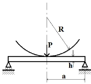
In this case of study, a circular plate, originally flat, is stamped by a spherical punch. This method has been described by T.X. Yu and W.J. Stronge [35] and this has been the first step for developing the second method with vacuum forming technique. The scheme of this method is shown in Figure 4.1.1.
20
Figure 4.1.1 – Punch scheme over the circular plate
Initially the punch contacts the surface of the flat plate. Increasing the normal deflection, the contact radius of the punch increases [36] as it shown in Figure 4.1.3 with the radius “b”. Applications of this method are shown in Figure 4.1.2 and 4.1.4.
21
Figure 4.1.3 – Contact area of the punch
22
The curvature of the punch has a resulting value of:
1
𝑅
=
𝑃
4𝜋𝐷
[
1 − 𝑣
2(1 + 𝑣)
(1 −
𝑏
2𝑎
2) − ln (
𝑏
𝑎
) ] 𝑓𝑜𝑟 𝑟 < 𝑏
Where:- a is the radius of the plate
- b is the contact radius of the punch - h is the thickness of the plate - R is the radius of the punch - v is the Poisson’s ratio
- D is the flexural rigidity of the plate - P is the total force of the punch
This curvature is proportional to the total force of the punch P divided by 4πD (D=Eℎ3/
12 (1-v2), where E is the Young’s modulus for the material). In the “Theory of Plates and Shells” written by S.Timoshenko and S.Woinowsky-Krieger [37] is shown that the deflection of an elastic plate stamped by a spherical punch can be represented as:
𝑤 =
{
𝑃
8πD
[(𝑏
2+ 𝑟
2) ln (
b
a
) + (𝑎
2− 𝑏
2)
(3 + 𝑣)𝑎
2− (1 − 𝑣)𝑟
22(1 + 𝑣)𝑎
2𝑓𝑜𝑟 0 ≤ 𝑟 ≤ 𝑏
𝑃
8πD
{(𝑎
2− 𝑟
2) [1 +
1 − 𝑣
2(1 + 𝑣)
(1 −
𝑏
2𝑎
2)] + (𝑏
2+ 𝑟
2) ln(
𝑟
𝑎
)}
𝑓𝑜𝑟 𝑏 ≤ 𝑟 ≤ 𝑎
This deflection can be written in nondimensional form as:𝛿 =
{
𝛼
2
(
𝐴
𝐵
− 𝜌
2)
𝑓𝑜𝑟 0 ≤ 𝜌 ≤ 𝛽
𝛼
2𝐵
{[(3 + 𝑣) − (1 − 𝑣)𝛽
2](1 − 𝜌
2) + 2(1 + 𝑣)(𝛽
2+ 𝜌
2) ln 𝜌}
𝑓𝑜𝑟 𝛽 ≤ 𝜌 ≤ 1
23 Where:
- 𝛿 =
𝑤ℎ- 𝛽 =
𝑏𝑎- 𝛼 =
𝑅ℎ𝑎2- 𝐴 = (3 + 𝑣)(1 − 𝛽
2) + 2(1 + 𝑣)𝛽
2ln 𝛽
- 𝐵 = (1 − 𝑣)(1 − 𝛽
2) − 2(1 + 𝑣) ln 𝛽
Consequently, the radial inclination 𝑑𝛿𝑑𝜌 is:
𝛿
′=
𝑑𝛿
𝑑𝜌
=
{
− 𝛼𝜌
𝑓𝑜𝑟 0 ≤ 𝜌 ≤ 𝛽
−
𝛼𝜌
𝐵
[2 − (1 − 𝑣)𝛽
2− (1 + 𝑣)(
𝛽
2𝜌
2+ 2 ln 𝜌) ]
𝑓𝑜𝑟 𝛽 ≤ 𝜌 ≤ 1
If the deflection of a circular plate is not small in comparison to the plate thickness, the radial displacements causes in-plane forces:
𝑁
𝑟=
𝐸ℎ
1 − 𝑣
2[
𝑑𝑢
𝑑𝑟
+
1
2
(
𝑑𝑤
𝑑𝑟
)
2+ 𝑣 (
𝑢
𝑟
)]
𝑁
𝜃=
𝐸ℎ
1 − 𝑣
2[
𝑢
𝑟
+ 𝑣 (
𝑑𝑢
𝑑𝑟
) +
𝑣
2
(
𝑑𝑤
𝑑𝑟
)
2]
Where:- u is the radial deflection - w is the transverse deflection
In the radial direction, the equilibrium equation can be written as:
𝑑
24
Then, substituting the in-plane forces in the previous equation:
𝑑
2𝑢
𝑑𝑟
2+
1
𝑟
(
𝑑𝑢
𝑑𝑟
) −
𝑢
𝑟
2= −
1 − 𝑣
2𝑟
(
𝑑𝑤
𝑑𝑟
)
2−
𝑑𝑤
𝑑𝑟
(
𝑑
2𝑤
𝑑𝑟
2)
These in-plane forces equations can be written in a nondimensional form substituting 𝜀 =𝑢𝑟:
𝜀
′+
𝑣𝜀
𝜌
+
ℎ
2𝑎
𝛿
′2=
𝑎(1 − 𝑣
2)𝑁
𝑟𝐸ℎ
2𝑣𝜀
′+
𝜀
𝜌
+
𝑣ℎ
2𝑎
𝛿
′2= 𝑎
(1 − 𝑣
2)𝑁
𝑟𝐸ℎ
2 and𝜀
′′+
𝜀
𝜌
−
𝜀
′𝜌
2= −
ℎ𝛿
′𝑎
(
1 − 𝑣
2𝜌
𝛿
′+ 𝛿
′′)
Substituting these equations with the plate inclination can be obtained:𝜀
′′+
𝜀
′𝜌
−
𝜀
𝜌
2=
{
−
ℎ𝛼
2𝜌(3 − 𝑣)
2𝑎
𝑓𝑜𝑟 0 ≤ 𝜌 ≤ 𝛽
(
ℎ𝛼
2𝑎𝐵
2) [𝑆
1𝜌
−3+ 𝑆
2𝜌
−1+ 𝑆
3𝜌
−1ln 𝜌 + 𝑆
4𝜌 + 𝑆
5𝜌 ln 𝜌 + 𝑆
6𝜌(ln 𝜌)
2]
𝑓𝑜𝑟 𝛽 ≤ 𝜌 ≤ 1
Where:-
𝑆
1=
(1+𝑣) 3𝛽4 2-
𝑆
2= −4𝑣(1 + 𝑣)𝛽
2− (1 + 𝑣)(1 − 𝑣)
2𝛽
4-
𝑆
3= −2(1 + 𝑣)
2(1 − 𝑣)𝛽
2-
𝑆
4= −2(1 − 3𝑣) + 4(1 − 𝑣
2)𝛽
2−
(1−𝑣) 2(3−𝑣)𝛽4 225
-
𝑆
5= 8(1 − 𝑣
2) − 2(1 − 𝑣
2)(3 − 𝑣)𝛽
2-
𝑆
6= −2(1 + 𝑣)
2(3 − 𝑣)
The equilibrium equation has a solution:
𝜀
1= 𝐶
11𝜌 +
𝐶
12𝜌
−
ℎ𝛼
2𝜌
3(3 − 𝑣)
16𝑎
for0 ≤ 𝜌 ≤ 𝛽
𝜀
2=
𝐶
21𝜌 +
𝐶
22𝜌
+ (
ℎ𝛼
2𝑎𝐵
2) {
𝑡
1𝜌
−1ln 𝜌 + 𝑡
2𝜌 ln 𝜌
+𝑡
3𝜌(ln 𝜌)
2+ 𝑡
4𝜌
3+ 𝑡
5𝜌
3ln 𝜌 + 𝑡
6𝜌
3(ln 𝜌)
2}
for𝛽 ≤ 𝜌 ≤ 1
Where:-
𝑡
1= −
𝑆21-
𝑡
2=
(2𝑆2−𝑆3) 4-
𝑡
3=
𝑆3 4-
𝑡
4=
8𝑆4−6𝑆645+7𝑆6-
𝑡
5=
2𝑆5−3𝑆6 4-
𝑡
6=
𝑆6 8If it’s considered a Poisson’s ratio equal to 0.3:
-
𝑡
1= −0.549𝛽
4-
𝑡
2= −0.189𝛽
2− 0.319𝛽
4-
𝑡
3= −0.592𝛽
2-
𝑡
4= −1.706 + 0.706𝛽
2− 0.083𝛽
4-
𝑡
5= 2.621 − 0.614𝛽
2-
𝑡
6= −1.141
26
As explained before, the wrinkling phenomenon occurs when the equilibrium configuration changes from axisymmetric bowl shape to a bowl containing radial waves in a compressed region near the edge. Yu and Stronge [35] assumed that the configuration can be described as a perturbation 𝛿̅separable with a function of radius and azimuth:
𝛿̅ = 𝜙(𝜌)𝜓(𝜃)
With this hypothesis it’s possible to adjust the previous equations and calculate the constants by writing the boundary conditions.
For both cases of study, the edge of the plate is free to move from the support, so:
𝜓(𝜃) ≤ 0
for0 ≤ 𝜃 ≤ 2𝜋
Assuming a periodic function of the form:
𝜓(𝜃) = sin(𝑛𝜃) − 1
where n is the number of wrinkling waves.Since it’s simply supported, the radial moment at the edge must be equal to zero.
𝑀
𝑟= −
𝐷ℎ
𝑎
2(
𝑑
2𝛿̅
𝑑𝜌
2+
𝑣
𝜌
𝑑𝛿̅
𝑑𝜌
) = 0 𝑎𝑡 𝜌 = 1
The equation that satisfy this condition is 𝑀𝑟(𝜌) = 0.Then:
𝜙
′′(𝜌) +
𝑣
𝜌
𝜙
′(𝜌) = 0 𝑓𝑜𝑟 𝜌
𝑤≤ 𝜌 ≤ 1
with 𝜌𝑤 inner radius of the wrinkled region.If there is a zero displacement at 𝜌𝑤
, 𝜙(𝜌) = (−𝜌
𝑤1−𝑣+ 𝜌
1−𝑣).
Then:
𝛿 = 𝐶(−𝜌
𝑤1−𝑣+ 𝜌
1−𝑣)(− sin(𝑛𝜃) + 1)
Knowing the boundary conditions it is possible to determine the constants 𝐶11, 𝐶12, 𝐶21, 𝐶22.
27
Assuming a Poisson’s ratio equal to 0.3:
𝐶
11=
ℎ
𝑎
(
𝛼
2𝐵
2) {0.776 − 0.403𝛽
2+ 2.092𝛽
2ln 𝛽 − 0.593𝛽
2(ln 𝛽)
2− 0.412𝛽
4+ 0.124𝛽
4ln 𝛽 + 0.040𝛽
5}
𝐶
12= 0
𝐶
21=
ℎ
𝑎
(
𝛼
2𝐵
2) {0.776 + 1.902𝛽
2− 1.027𝛽
4+ 0.443𝛽
4ln 𝛽 + 0.040𝛽
6}
𝐶
22=
ℎ
𝑎
(
𝛼
2𝐵
2) {−0.682𝛽
4+ 0.823𝛽
4ln 𝛽 + 0.074𝛽
6}
Consequently the in-plane forces will be:
𝑁
𝑟=
12𝐷𝛼
2𝑎
2𝐵
2{1.3𝐶
̅̅̅̅ − 0.057𝐵
11 2𝜌
2}
𝑁
𝜃=
12𝐷𝛼
2𝑎
2𝐵
2{1.3𝐶
̅̅̅̅ − 0.171𝐵
11 2𝜌
2}
for0 ≤ 𝜌 ≤ 𝛽
𝑁
𝑟=
12𝐷𝛼
2𝑎
2𝐵
2{1.3𝐶
̅̅̅̅ − 0.7𝐶
11̅̅̅̅ + (3.3𝑡
22 4+ 𝑡
5)𝜌
2+ (3.3𝑡
5+ 2𝑡
6)𝜌
2ln 𝜌
+ 3.3𝑡
6𝜌
2(ln 𝜌)
2+ 𝑡
2+ (1.3𝑡
2+ 2𝑡
3) ln 𝜌 + 1.3𝑡
3(ln 𝜌)
2+ 𝑡
1𝜌
−2− 0.7𝑡
1𝜌
−2ln 𝜌
+
𝜌
22
[−2 + 0.7𝛽
2+ 2.6 ln 𝜌 +
1.3𝛽
2𝜌
2]
2}
𝑁
𝜃=
12𝐷𝛼
2𝑎
2𝐵
2{1.3𝐶
̅̅̅̅ − 0.7𝐶
11̅̅̅̅ + (1.9𝑡
22 4+ 0.3𝑡
5)𝜌
2+ (1.9𝑡
5+ 0.6𝑡
6)𝜌
2ln 𝜌 + 1.9𝑡
6𝜌
2(ln 𝜌)
2+ 0.3𝑡
2+ (1.3𝑡
2+ 0.6𝑡
3) ln 𝜌 + 1.3𝑡
3(ln 𝜌)
2+ 0.3𝑡
1𝜌
−2+ 0.7𝑡
1𝜌
−2ln 𝜌 + 0.15𝜌
2[−2 + 0.7𝛽
2+ 2.6 ln 𝜌 +
1.3𝛽
2𝜌
2]
2}
for𝛽 ≤ 𝜌 ≤ 1
28
With
𝐶
̅̅̅̅ = 𝐶
𝑖𝑗 𝑖𝑗/(
ℎ𝑎
)(
𝛼2 𝐵2).
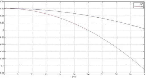
Assuming a 𝛽 = 0.5 the in-plane forces are shown in Figure 4.1.3.
Figure 4.1.4 – In-plane forces
At this punch displacement, the radial in-plane force is tensile throughout the entire plate, while the circumferential force is positive near the center and negative near the edge.
Knowing the in-plane forces behavior it’s necessary for predict the wrinkling phenomenon. The method for study this problem is already been used for deep-drawing processes for clamped circular plates [17].
To establish the wrinkling criterion an energy integral method has been used [38]. The bending and stretching energy need to be determined.
According to Timoshenko studies, the bending energy can be written as:
∆𝑈
𝑏=
𝐷ℎ2 2𝑎2∫ ∫ {(
𝑑2𝛿̅ 𝑑𝜌2+
1 𝜌(
𝑑𝛿̅ 𝑑𝜌) +
1 𝜌2(
𝑑2𝛿̅ 𝑑𝜃2)
2− 2(1 − 𝑣)
𝑑2𝛿̅ 𝑑𝜌2(
1 𝜌(
𝑑𝛿̅ 𝑑𝜌) +
1 𝜌𝑤 2𝜋 0(
𝜌12) (
𝑑𝑑𝜃2𝛿̅2) + 2(1 − 𝑣) (
1𝜌𝑑𝜌𝑑𝜃𝑑2𝛿̅−
𝜌12(
𝑑𝛿̅𝑑𝜃)
2} 𝜌 𝑑𝜌 𝑑𝜃
Knowing the previous assumptions for boundary conditions, the previous equation will be:
∆𝑈
𝑏=
𝜋
2
𝐷𝐶
2(
ℎ
229 Where:
𝐹(𝛽, 𝑛, 𝜌
𝑤) = (0.6282𝑛
4− 0.8795𝑛
2+ 2.2295)𝜌
𝑤−0.6− (1.6667𝑛
4− 1.9133𝑛
2+ 0.7432)
+ (1.5385𝑛
4− 0.33338𝑛
2)𝜌
𝑤0.7− (0.5𝑛
4+ 0.7𝑛
2)𝜌
𝑤1.4The stretching energy will be [3]:
∆𝑈
𝑠=
ℎ
22
∫ ∫ {𝑁
𝑟(
𝑑𝛿̅
𝑑𝜌
)
2+ 𝑁
𝜃(
𝑑𝛿̅
𝜌𝑑𝜌
)
2} 𝜌 𝑑𝜌 𝑑𝜃
1 𝜌𝑤 2𝜋 0Since the in-plane forces are already determined, the stretching energy will be:
∆𝑈
𝑠= 6𝜋𝐷𝑐
2(
ℎ
2𝑎
2) 𝐺(𝛽, 𝑛, 𝜌
𝑤)
Where:𝐺(𝛽, 𝑛, 𝜌
𝑤) = ∫ {3(1 − 𝑣)
2𝜌
−2𝑣(
𝑁
𝑟12𝐷 (
𝛼
𝑎
22)
)
1 𝜌𝑤+ 𝑛
2(𝜌
−𝑣− 𝜌
𝑤1−𝑣𝜌
−1)
2(
𝑁
𝜃12𝐷 (
𝛼
𝑎
22)
) 𝜌 𝑑𝜌
G can be calculated by fixing a value of 𝛽, 𝑛, 𝜌𝑤.For knowing the exact value of deflection where wrinkling begins, the stretching energy and the bending energy must be equal.
Then:
𝐹(𝛽, 𝑛, 𝜌
𝑤) = 12𝛼
2𝐺(𝛽, 𝑛, 𝜌
𝑤)
The relation between the center of deflection and the contact radius is:
𝛿
0𝛼
=
𝐴
2𝐵
=
((3 + 𝑣)(1 − 𝛽
2) + 2(1 + 𝑣)𝛽
2ln 𝛽)
2(1 − 𝑣)(1 − 𝛽
2) − 4(1 + 𝑣) ln 𝛽
For this method, n and 𝜌𝑤are parameters. For knowing the exact value of 𝛿0 must be scanned each value of 𝜌𝑤from 0 to 1, the lowest value of the displacement will be the right one.
30
4.2 Wrinkling of a circular elastic plate using
vacuum forming
This case of study is similar to the previous one, but with some differences.
A flat elastic plate is formed by using a vacuum forming machine. This mean that the pressure over the surface will be constant and without any contact region like the punch as it showed in Figure 4.2.1.
Figure 4.2.1 – Circular elastic plate under uniform load
According to Theory of Plates and Shells of Timoshenko, the new deflection of the plate will be:
𝑤 =
𝑃
0𝑎
464 𝐷
[1 − (
𝑟
𝑎
)
2] [
5 + 𝑣
1 + 𝑣
− (
𝑟
𝑎
)
2]
Where:- 𝑃0is the load over the plate
- D is the flexural rigidity of the plate - a is the radius of the plate
- h is the thickness of the plate - v is the Poisson’s ratio - r is the radial coordinate
31
Since it has been necessary avoid the parameter 𝑃0and find a relation between the pressure and the geometry some calculations have been done.
The maximum value of the displacement will be at r = 0. Then:
𝑤
𝑚𝑎𝑥(𝑟 = 0) =
𝑃
0𝑎
464 𝐷
[
5 + 𝑣
1 + 𝑣
]
Knowing the radius of final curvature R it’s possible to find an easy relation between wand R as it shown in Figure 2.2.2
Figure 4.2.2 – Relation between w and R
𝑤
𝑚𝑎𝑥2− 2𝑅𝑤
𝑚𝑎𝑥+ 𝑎
2= 0
𝑤
𝑚𝑎𝑥22𝑤
𝑚𝑎𝑥+
𝑎
22𝑤
𝑚𝑎𝑥= 𝑅
𝑤
𝑚𝑎𝑥2
≪
𝑎
22𝑤
𝑚𝑎𝑥𝑅~
𝑎
22𝑤
𝑚𝑎𝑥 Linking this equation to the first one:𝑅 =
64𝐷
2𝑎
2𝑃
0(
1 + 𝑣
5 + 𝑣
)
𝑃
0=
64𝐷
2𝑎
2𝑅
(
1 + 𝑣
5 + 𝑣
)
32
It has been found a relation between 𝑃0and R.
𝑤 =
64𝐷
2𝑎
2𝑅
(
1 + 𝑣
5 + 𝑣
)
𝑎
464 𝐷
[1 − (
𝑟
𝑎
)
2] [
5 + 𝑣
1 + 𝑣
− (
𝑟
𝑎
)
2]
𝑤 =
𝑎
22𝑅
(
1 + 𝑣
5 + 𝑣
) [1 − (
𝑟
𝑎
)
2] [
5 + 𝑣
1 + 𝑣
− (
𝑟
𝑎
)
2]
Again it’s possible to write the displacement in a nondimensional form dividing by the thickness h:
𝛿 =
𝛼
2
(
1 + 𝑣
5 + 𝑣
) [1 − (
𝑟
𝑎
)
2] [
5 + 𝑣
1 + 𝑣
− (
𝑟
𝑎
)
2]
Where:-
𝛼 =
𝑎 2 𝑅ℎThe radial inclination will be:
𝛿
′= −𝛼𝜌 (
1 + 𝑣
5 + 𝑣
) − 𝛼𝜌 +
4𝜌
3𝛼
2
(
1 + 𝑣
5 + 𝑣
)
The new differential equation then will be:𝛿
′′= −𝛼 (
6 + 2𝑣
5 + 𝑣
) + 6 (
1 + 𝑣
5 + 𝑣
) 𝛼𝜌
2𝜀
′′+
𝜀
𝜌
−
𝜀
′𝜌
2= −
ℎ𝛿
′𝑎
(
1 − 𝑣
2𝜌
𝛿
′+ 𝛿
′′)
= −
ℎ
𝑎
(−𝛼 (
6 + 2𝑣
5 + 𝑣
) 𝜌
+ 2𝛼 (
1 + 𝑣
5 + 𝑣
) 𝜌
3) [(
1 − 𝑣
2𝜌
) (−𝛼 (
6 + 2𝑣
5 + 𝑣
) 𝜌
+ 2𝛼 (
1 + 𝑣
5 + 𝑣
) 𝜌
3) + (−𝛼 (
6 + 2𝑣
5 + 𝑣
) + 6𝛼 (
1 + 𝑣
5 + 𝑣
) 𝜌
2)]
33
When r=0 the displacement will be:
𝛿
0𝛼
=
1
2
Where:-
𝜌 =
𝑟 𝑎The wrinkling begins then:
𝛿
0=
1
2
[
𝐹(𝛽, 𝑛, 𝜌
𝑤)
12𝐺(𝛽, 𝑛, 𝜌
𝑤)
]
0.535
5
. Discussion of results
_____________________________________________________________________________
The wrinkling criterion for the smallest wave-numbers n have been computed for v=0.3. All of the results are shown on a 1/α, 𝛿0 map.
𝛿0 = 𝑤/ℎ
𝛼 =
𝑅ℎ
𝑎
2The Figure 5.1 shows the results of the circular elastic plate stamped by a spherical punch.
Figure 5.1 – The initiation of wrinkling of the circular elastic plate stamped by a spherical punch
36
The equation for the initiation of wrinkling has been analyzed for different wave-numbers. This figure indicates that:
- Elastic wrinkling does not occur until the deflection of the plate is about four times the plate thickness
- Wrinkling initiates in a four wave mode of deformation
- Wrinkling depends more on the thickness/displacement ratio instead of the 1/𝛼 ratio
The Figure 5.2 shows the results of the circular elastic plate using vacuum forming.
Figure 5.2 – The initiation of wrinkling of the circular elastic plate using vacuum forming
In this case the wrinkling phenomenon occurs earlier. This is due to the fact that the presence of the punch mechanically block the formation of wrinkles.
Looking at the results, it is easy to understand how the displacement 𝛿0 changes on
varying the number of wrinkles. By increasing 𝛿0 the plate will move to a 4-waves to an
higher waves configuration.
FEM analysis in Figure 5.3 show the increasing wave numbers by increasing the contact area of the punch (i.e. increasing the displacement).
37
a b c
Figure 5.3 – Buckling mode shapes (a- without transversal waves, b- with 4 waves, c- with 8 waves)
The analytical models have been tested also for different materials with different Poisson’s ratios as it shown in Figure 5.4. This test provide a good understanding of the dependence of the wrinkling phenomenon and the temperature of the plate (during a Creep age forming).
38
5.1 Experimental results
Figure 5.1.1 Validation of the model
According to an experimental result presented by M.P.F. Sutcliffe [27], the model has been set with the correct values of his Aluminum alloy. The data are showing several test with different values of the plate radius a, the negative mold radius R and with an increasing thickness from 1.2mm to 3.1mm. In Figure 5.1.1 are overlapped the results and the predictions. The analytical model underestimate the phenomenon. One of the causes is the poor dependence of thickness variation during the forming process. Sutcliffe used a punch with a large radius. The large radius punch have been always in full contact with the surface. This have been the closest experiment result comparable with a vacuum forming technique.
Vacuum forming process can be stopped only in two cases:
- when the sheet completely cover the negative mold (there is no more air)
- when the borders of the sheet stop to be in contact with the mold (air flows in the negative mold)
39
Figure 5.1.2 – Vacuum forming trials at room temperature
These results show a ten times higher 𝛿0 . This is due to the fact that the tests stopped only when a bigger wrinkle has been formed as shown in Figure 5.1.3.
Figure 5.1.3 – Snapthrough
Plates transform from a four- to an higher lobe mode of wrinkling during a single stroke of stamping. Over a certain high lobe mode, on the wrinkle plate start to grow a big wrinkle: this phenomenon is called snapthrough. It is a bifurcation buckling of the plate
40
rather than wrinkling. The circumferential curvature changes from the smooth flexure of wrinkling to flexure concentrated along narrow, radial, plastic hinge lines. The test, during vacuum forming, is no more in contact with mold and then stop.
Therefore, the results in Figure 5.1.2 don’t show a wrinkled or an unwrinkled test but a test with the snapthrough phenomenon or not.
In Figure 5.1.4 is clear that the circular plate was already wrinkled, reaching a 36-lobe wrinkles, before the snapthrough.
Figure 5.1.4 – Snapthrough and wrinkling phenomenon
Creep forming process has been adopted for avoid wrinkling phenomenon. By increasing the temperature, snapthrough phenomenon showed up at higher displacements as it shown in Figure 5.1.5.
41
43
6
. Conclusions
_____________________________________________________________________
An analytical model for prediction of wrinkling has been presented. Both of the discussed cases were been discussed in detail. Elastic wrinkling does not occur until
𝑤0
ℎ ≈ 4 if the plate is loaded by a spherical punch and 𝑤0
ℎ ≈ 3 if the plate is under
uniform pressure. With increasing displacement beyond the initiation of wrinkling, the deformation mode changes to a larger number of waves.
From the analytical model the wrinkles phenomenon begins with a 4-lobe configuration up to undefined number of wrinkles. From the experimental results has been noticed that this number stops growing when the snapthrough phenomenon occur.
The model shows also that by increasing the Poisson’s ratio of the material, the wrinkles begins at higher displacements. This is directly related to the temperature of the material, which has been tested also at different temperatures with a creep forming technique.
The design of the new Rear Pressure Bulkhead requires a displacement higher than 𝑤0 = 500mm. Since it needs to be light, it’s not possible to use this forming processes without occurring in wrinkling phenomenon. Neither of the wrinkles or snapthrough are acceptable for this component.
Therefore, the Rear Pressure Bulkhead cannot be formed with this processes.
These techniques, however, can be useful for other components with lower displacements. Thus, a more detailed experimental analysis is required for having better results at the beginning of wrinkling since the beginning of 4-lobes configuration was difficult to study during vacuum forming technique.
45
7
. Bibliography
______________________________________________________________________
[1] R.Pierce, Sheet metal forming, IOP Publishing, 1991 (partly accessible through books.google.com)
[2] J.W.Hutchinson, K.W.Neale, “Wrinkling of curved thin sheet metal”, Plastic Instability, Considère Memorial Symposium, Presses Ponts et Chaussées, Paris, pp.71-78, 1985
[3] Cao J., Boyce M., “Wrinkle behavior of rectangular plates under lateral constraint”, Internal Journal of Solids and Structure 1997; 34(2); 153-76.
[4] Cao J, Karafillis A., Ostrowski M., “Prediction of flange wrinkles in deep drawing”. In: Predeleanu, Gilormini P, editors. Advanced methods in material processing defects. 1997, pp. 301-10.
[5] Wang X, Cao J. “An analytical model for predicting flange wrinkling in deep drawing”. Transactions of NAMRI SME 1998;XXVI:25}30.
[6] Cao J, Wang X. “An analytical model for plate wrinkling under tri-axial loading and its application”. International Journal of Mechanical Sciences 1999;42(3):617}33.
[7] Tomita Y. Simulations of plastic instabilities in solid mechanics. Applied Mechanical Reviews 1994;47:171}205.
[8] Esche SK, Kinzel GL, Taylan A. Review of failure analysis in sheet metal forming simulations. In: Lee JK, Kinzel GL, Wagoner RH, editors. Numisheet'96. 1996. p. 270}9.
[9] Neale KW, Tugcu P. A numerical analysis of wrinkle formation tendencies in sheet metals. International Journal for Numerical Methods in Engineering 1990;30:1595}608. [10] Tug(cu P. Plate buckling in the plastic range. International Journal of Mechanical Sciences 1991.
[11] Tug(cu P. On plastic buckling prediction. International Journal of Mechanical Sciences 1991.
46
[12] Wang CT, Kinzel G, Altan T. Wrinkling criterion for an anisotropic shell with compound curvatures in sheet forming. International Journal of Mechanical Sciences 1994.
[13] Triantafyllidis N. Puckering instability phenomena in the hemispherical cup test. Journal of Mechanical Physics Solids 1985.
[14] Fatnassi A, Tomita Y, Shindo A. Non-axisymmetric buckling behavior of elastic-plastic circular tubes subjected to a nosing operation. International Journal of
Mechanical Sciences 1985.
[15] Zhang LC, Yu TX, Wang R. Investigation of sheet metal forming by bending, Part II: plastic wrinkling of circular sheets pressed by cylindrical punches. International Journal of Mechanical Sciences 1989.
[16] Senior BW. Flange wrinkling in deep-drawing operation. Journal of Mechanical Physics Solids 1956.
[17] T.X.Yu, W.Johnson, “The buckling of annular plates in relation to the deep-drawing process”. Int. J. Mech. Sci. 24, 175-188, 1982
[18] Yoshida K, Hayashi J, Hirata M. Yoshida buckling test, IDDRG, 1981, Kyoto, Japan.
[19] Tomita Y, Shindo A. Onset and growth of wrinkles in thin square plates subjected to diagonal tension. International Journal of Mechanical Sciences 1988.
[20] Mackerle J., “Finite element analyses and simulations of sheet metal forming processes”, Engineering Computations, Vol. 21 No.8, 2004, pp. 891-940
[21] Ambrogio, G., Constantino I., De Napoli L., Filice L., Fratini L., Muzzupappa M. “Infuence of some relevant process parameters on the dimensional accuracy in
incremental forming: a numerical and experimental inverstigation.” Journal of Materials, Processing Technology 153-154, 501 507, 2004
[22] S. Yalçin, “Analysis and modeling of plastic wrinkling in deep drawing”, Master thesis, Middle East Technical University, September 2010
[24] T. Meinders, S. Selman, E. H. Atzema, H. Huétink, “Wrinkling Prediction in Sheet Metal Forming and Experimental Verification“,VII International Conference on
Computational Plasticity COMPLAS, 2003
[25] W. F. Hosford, J. L. Duncan, “Sheet Metal Forming: A Review”, JOM, pp. 39-44, November 1999
47
[26] A. M. Szacinski, P. F. Thomson, “Wrinkling behaviour of aluminium sheet during forming at e!evated temperature”, Material Science and Technology, Volume 37, pp.37-41, January 1991
[27] M.P.F. Sutcliffe, W.J.Stronge, T.X.Yu, “Wrinkling of elastoplastic circular plates during stamping”, Int. J. Solid Structures, 1985
[28] Kim J.B., Yang D.Y.: "Prediction of wrinkling initiation in sheet metal forming processes", Engineering Computations, Vol.20 No.1, 2003, p 6-39
[29] Z.Istvanic, S.Lemes, N.Zaimovic-Uzmovic, “Buckling mode shapes in incremental forming of sheet metal”, Metal Invest Jajce, 2008
[30] http://www.custompartnet.com/wu/sheet-metal-forming, last accessed; 15th August 2014.
[31] Metal Forming Handbook, Schuler, Springer-Verlag, Berlin Heidelberg, 1998.
[32] C.Wang, “Mechanics of bending, flanging, and deep drawing and a computer-aided modelling system for predictions of strain, fracture, wrinkling and springback in sheet metal forming”, PhD thesis, The Ohio State University, 1993
[33] F.C. Ribeiro, E.P. Marinho, D.J. Inforzato, P.R. Costa, G.F. Batalha, “Creep age forming: a short review of fundaments and applications”, Journal of Achievements in Materials and Manufacturing Engineering, Volume 43, Issue 1, November 2010
[34] M.C. Holman, Autoclave age forming large aluminum aircraft panels, Journal of Mechanical Work Technology 20 (1989) 477-488.
[35]. T.X.Yu, W.J.Stronge, “Wrinkling of a circular elastic plate stamped by a spherical punch”, Int. J. Solids Structures Vol. 21. No. 10. pp. 995-1003, 1985
[36]. T.X.Yu, W. Johnson and W.J.Stronge, “Stamping and springback of circular plates deformed in hermispherical dies”, Int. J. Mech. Sci. 26, 131-148, 1984
[37] S.Timoshenko, S.Woinowsky-Krieger, “Theory of Plates and Shells”, 2nd Ed. McGraw-Hill, 1959
[38] S.Timoshenko and J.M.Gere, “Theory of Elastic Stability”, 2nd Ed., McGraw-Hill, 1959
[39] Autoclave Products – American Autoclave S.A., (2015, February 03). Reviewed from URL http://www.americanautoclave.com.mx/
![Figure 2.1 – Creep age forming process stages [33]](https://thumb-eu.123doks.com/thumbv2/123dokorg/7445349.100632/9.892.128.766.741.904/figure-creep-age-forming-process-stages.webp)
![Figure 2.2 – Autoclave used for Creep Age forming technique [39]](https://thumb-eu.123doks.com/thumbv2/123dokorg/7445349.100632/10.892.131.764.105.586/figure-autoclave-used-creep-age-forming-technique.webp)
![Figure 3.1 – Schematic of a Deep Drawing Operation [5]](https://thumb-eu.123doks.com/thumbv2/123dokorg/7445349.100632/11.892.255.658.710.963/figure-schematic-deep-drawing-operation.webp)
![Figure 3.3 – Deep drawing process [30]](https://thumb-eu.123doks.com/thumbv2/123dokorg/7445349.100632/12.892.222.676.816.1105/figure-deep-drawing-process.webp)
![Figure 3.4 – Deep drawing process [31]](https://thumb-eu.123doks.com/thumbv2/123dokorg/7445349.100632/13.892.161.730.325.503/figure-deep-drawing-process.webp)
![Figure 3.5 – Flange wrinkles during deep drawing [28]](https://thumb-eu.123doks.com/thumbv2/123dokorg/7445349.100632/14.892.229.669.124.363/figure-flange-wrinkles-during-deep-drawing.webp)
![Figure 3.1.1 – Double-curved surface [27]](https://thumb-eu.123doks.com/thumbv2/123dokorg/7445349.100632/16.892.259.637.278.506/figure-double-curved-surface.webp)
![Figure 4.1.4 – Contact area of the punch – test [27]](https://thumb-eu.123doks.com/thumbv2/123dokorg/7445349.100632/21.892.213.681.492.1035/figure-contact-area-punch-test.webp)