Journal of Sustainable Development of Energy, Water and Environment Systems
http://www.sdewes.org/jsdewes
Year 2018, Volume 6, Issue 1, pp 210-226
210
Journal of Sustainable Development of Energy, Water and Environment Systems
http://www.sdewes.org/jsdewes
Sulfur Rich Coal Gasification and Low Impact Methanol Production
Andrea Bassani1, Giulia Bozzano2, Carlo Pirola3, Caterina Frau4, Alberto Pettinau5, Enrico Maggio6, Eliseo Ranzi7, Flavio Manenti*8
1Politecnico di Milano, Dipartimento CMIC “Giulio Natta”, Piazza Leonardo da Vinci 32,
20133 Milano, Italy
e-mail: [email protected]
2Politecnico di Milano, Dipartimento CMIC “Giulio Natta”, Piazza Leonardo da Vinci 32,
20133 Milano, Italy
e-mail: [email protected]
3Università degli Studi di Milano, Dipartimento di Chimica, Via Golgi 19, 20133 Milano, Italy
e-mail: [email protected]
4Sotacarbo S.p.A., c/o Grande Miniera di Serbariu, 09013 Carbonia, Italy
e-mail: [email protected]
5Sotacarbo S.p.A., c/o Grande Miniera di Serbariu, 09013 Carbonia, Italy
e-mail: [email protected]
6Sotacarbo S.p.A., c/o Grande Miniera di Serbariu, 09013 Carbonia, Italy
e-mail: [email protected]
7Politecnico di Milano, Dipartimento CMIC “Giulio Natta”, Piazza Leonardo da Vinci 32,
20133 Milano, Italy
e-mail: [email protected]
8Politecnico di Milano, Dipartimento CMIC “Giulio Natta”, Piazza Leonardo da Vinci 32,
20133 Milano, Italy
e-mail: [email protected]
Cite as: Bassani, A., Bozzano, G., Pirola, C., Frau, C., Pettinau, A., Maggio, E., Ranzi, E., Manenti, F., Sulfur Rich Coal Gasification and Low Impact Methanol Production, J. sustain. dev. energy water environ. syst., 6(1), pp 210-226,
2018, DOI: https://doi.org/10.13044/j.sdewes.d5.0188
ABSTRACT
In recent times, the methanol was employed in numerous innovative applications and is a key compound widely used as a building block or intermediate for producing synthetic hydrocarbons, solvents, energy storage medium and fuel. It is a source of clean, sustainable energy that can be produced from traditional and renewable sources: natural gas, coal, biomass, landfill gas and power plant or industrial emissions. An innovative methanol production process from coal gasification is proposed in this work. A suitable comparison between the traditional coal to methanol process and the novel one is provided and deeply discussed. The most important features, with respect to the traditional ones, are the lower carbon dioxide emissions (about 0.3%) and the higher methanol production (about 0.5%) without any addition of primary sources. Moreover, it is demonstrated that a coal feed/fuel with a high sulfur content allows higher reductions of carbon dioxide emissions. The key idea is to convert hydrogen sulfide and carbon dioxide into syngas (a mixture of hydrogen and carbon monoxide) by means of a regenerative thermal reactor. This is the Acid Gas to Syngas technology, a completely new and effective route of processing acid gases. The main concept is to feed an optimal ratio of hydrogen sulphide and carbon monoxide and to preheat the inlet acid gas before the combustion. The reactor is simulated using a detailed kinetic scheme.
and Environment Systems Volume 6, Issue 1, pp 210-226
KEYWORDS
Carbon dioxide reuse, Methanol synthesis, Improved coal gasification, Syngas from hydrogen sulphide and carbon dioxide emissions.
INTRODUCTION
Methanol (CH3OH) production and demands are increasing over last decade [1] in
particular in China and developing countries [2]. Indeed, the productions of several chemicals like formaldehyde [3], methyl-tert-butyl ether [4], acetic acid [5] and dimethyl ether [6], are based on methanol as primary reactant. Moreover, CH3OH could be used as
additive to gasoline [7]. Nowadays there are different industrial and “under development” way to produce methanol due to its importance as base chemical. However, the most widespread process operates at pressures of 50-150 bar and temperatures of 200-350 °C using syngas as primary feedstock [8] like the one provided by ICI company [9] or by Lurgi [10]. These are copper based catalytic process [11] that operates in gas phase with the only difference related to the reactor. As already mentioned before, methanol could be manufactured in different and new ways. One of the most promising way in terms of carbon footprint is the one that use Carbon dioxide (CO2) as carbon source for methanol
production. Indeed, this production pathway could contribute to mitigate the global warming [12]. Said this, there are different sources that could be used for methanol production and so the so-called the “Methanol Economy” [13] offers a feasible and environmentally friendly mean of using and storing all sources of energy (renewable, atomic, etc.). Another important aspect that has to be considered is how the syngas is produced because it is crucial to focus the attention on the yield and the quality of the syngas, mostly in terms of Hydrogen (H2) and Carbon monoxide (CO) ratio
[14, 15]. In fact, the downstream catalytic processes (i.e. methanol synthesis) typically need to be fed with a syngas with a proper composition: H2/CO ≈ 2 [16]. Nowadays the
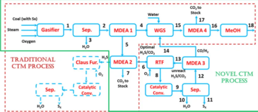
main pathway for syngas production is the reforming of natural gas [17]. However, the partial oxidation of different carbon-based materials like coal, heavy oil or biogas could deserve a special mention [18, 19]. Coals are of particular interest due to their relatively low cost, widespread availability and distribution and less exposed to political constraints [20]. Unfortunately, Coal-to-Methanol (CTM) production is an energy and water intensive industry that creates considerable environmental pollution [21]. Annual average production of methanol in the world from CTM plants is about 1,000,000 tons per year [22]. A very schematic CTM process diagram based on a Coal Gasification (CG) [23] is shown in Figure 1.
Figure 1. Process diagram of conventional coal-based gasification process for methanol production
Coal is gasified at high temperature (1,200-1,600 °C) and high pressure (20-50 bar) to produce raw syngas, which contains mainly H2 and CO as well as small amounts of other
gases, such as CO2, Hydrogen sulphide (H2S), and Methane (CH4) [24]. Sulfur
compounds and CO2 are removed from the syngas in the Acid Gas Removal (AGR) unit.
The purified syngas is processed in the Water Gas Shift (WGS) unit to achieve the optimal H2/CO ratio for methanol synthesis. Finally, the syngas is compressed and fed to
and Environment Systems Volume 6, Issue 1, pp 210-226
the Methanol Synthesis (MS) unit. However, according to a study made by Qin et al. [25], the life cycle carbon footprint of CTM process is 2.6-3.6 tons of CO2 per ton of Methanol
(MeOH). For this reason, Carbon Capture and Storage (CCS) technology has been studied by various researchers [26]. CCS is a process consisting of the CO2 capture from
industrial and energy-related sources, CO2 compression, its transportation and long term
storage. Introduction of CCS technology would considerably reduce CO2 emission.
However, carbon capture again consumes a lot of energy [27]. Therefore, CTM process is a cause of environmental concern and not only because of the greenhouse effects resulting from the CO2 emissions. Indeed, hydrogen sulfide is a common byproduct in
coal gasification process and the strict legislation that limits its release into the atmosphere has triggered renewed interest in the modeling of sulfur chemistry [28]. The most important and used neutralization method is the Claus process [29]. Based on recent advances [30] and patented technology [31], it could be also possible to convert H2S and
CO2 into valuable products and specifically into syngas. The oxy-reduction reaction takes
place into a Regenerative Thermal Reactor (RTR):
2 2 2 2 2
2H S CO+ =CO+H +S +H O (1)
The Acid Gas to Syngas (AG2S) technology exploits the hydrogen content of H2S as
reducing agent for CO2 [32] and, at the same time, allows to use energy sources currently
still unexploited because of their relevant sulfur content. Crude oils, natural gases and different coals with high sulfur contents are promising candidates for this technology [33]. The target of this study is to evaluate the potential application of AG2STM technology on CTM in terms of reduction of emissions and methanol production. Moreover, it will be possible to show that higher content in sulfur means both lower emissions of CO2 (without any additional environmental impact due to organosulfur
species) and a surplus of methanol production without any addition of primary sources.
PROCESS AND SIMULATION TOOLS DESCRIPTION
In this paragraph, the overall layout of the novel CTM process is discussed and then each part is analyzed with a description of models and tools. Aspen HYSYS®,
a commercial process simulation software [34], is adopted for this simulation using Peng-Robinson-Styjek-Vera (PRSV) [35, 36] as equation of state except for the amine wash that have a dedicated amine fluid package included into Aspen HYSYS. Despite this, the coal gasifier and the Regenerative Thermal Furnace (RTF) are simulated using external tools as described in the next paragraphs. Figure 2 shows a simplified block flow diagram comparing the traditional CTM process with the new one.
and Environment Systems Volume 6, Issue 1, pp 210-226 Coal gasification
Coal gasifier is simulated using GASDS [37]. As schematically shown in Figure 3, this program includes a multi-scale, multi-phase and multi-component model which describe coal gasification system by means of detailed kinetic mechanisms for coal pyrolysis, char heterogeneous reactions and for successive gas-phase reactions [38]. It also includes the catalytic effect of ashes [39]. These kinetic mechanisms are then coupled with transport resistances resulting in first-principles dynamic modeling of non-ideal reactors of different types (e.g., downdraft, updraft, traveling grate).
Figure 3. Multiscale nature and structure of a countercurrent coal gasifier [40] Amine washing units
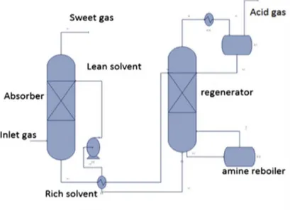
The aim of the amine wash unit is to purify the syngas, that contains acid gases (H2S
and CO2), coming from coal gasifier. Methyl Diethanolamine (MDEA) was chosen for
its industrial application and its specific selectivity to hydrogen sulfide [41]. As already highlighted by Bassani et al. [30], it is necessary to apply at least three amine washing units. The first one allows both to sequestrate H2S from the acid gas stream, and at the
same time, to control the absorption of CO2. Indeed, the inlet ratio between H2S and CO2
is a first crucial operative parameter for AG2S process. For instance, working with an excess of CO2 is not convenient because CO2, the main source of CO, would be an “heat
absorber” in the Regenerative Thermal Reactor (RTR) of the AG2S process section. In fact, if there is an excess of CO2, more oxygen should be required to reach the desired
temperature, leading to a greater oxidation of H2S, limiting its pyrolysis with the net
reduction of syngas yield. The second amine-washing unit aims to adjust the ratio between H2S and CO2. Indeed, AG2S process requires a ratio at least 2 [i.e. the
stoichiometric ratio of reaction (1)]. This amine wash unit is not required in novel CTM process if the ratio H2S/CO2 coming from the first amine unit is already ~2. On the
contrary, H2S is almost completely separated from CO2 in the traditional process in order
to be sent to the Claus process [42]. Finally, the third amine-washing unit splits the extra syngas produced in RTR from the unreacted acid gases, which are recycled to the AG2S process. Moreover, an additional amine wash unit is required in CTM process both in case of traditional and novel process. This unit removes the CO2 from the syngas stream
after the Water-Gas-Shift (WGS) reactor. However, a minor percentage of CO2
(1-4 %mol) remains in the stream and can be useful in methanol process [43].
The amine washing section is simulated entirely through HYSYS software, with a template already existing in the commercial package. The configuration of an amine
and Environment Systems Volume 6, Issue 1, pp 210-226
treatment unit is composed of a single absorption column, one regeneration column and all related equipment, such as pumps, heat exchangers and filters, as schematically reported in Figure 4.
Figure 4. MDEA wash with regenerator Acid Gas to Syngas technology
The acid gas stream coming from sweetening section is sent to the Acid Gas to Syngas (AG2S™) process [30]. The core of the plant is the RTR, which has a different configuration compared with the typical Claus furnace [44]. RTR is mainly composed by a furnace, a Waste Heat Boiler (WHB) and a heat exchanger. This design allows to produce a greater amount of H2. The key idea is to feed an optimal ratio of H2S and CO2
and to preheat the inlet acid gas before the combustion. In this way, H2S pyrolysis
produces hydrogen selectively. Indeed, it is convenient to feed the acid gases to the RTR at high temperatures (e.g. 700 °C) in order to reduce the oxygen flow rate required to reach the furnace temperatures (1,100-1,350 °C). So, the oxygen stream is much lower than the typical oxygen provided to the Claus processes and the H2S potential for
pyrolysis is completely exploited.
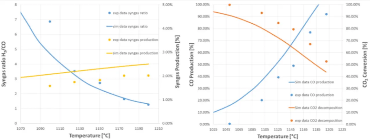
It is important to emphasize that the reactor is simulated using DSMOKE software with a detailed kinetic scheme [45]. The latter is coupled within Aspen HYSYS® with the use of MATLAB. This allows to include the detailed kinetics, within non-ideal reactor models and in turn into commercial environments for the simulation of chemical plants. The detailed kinetic scheme selected is made up of three different subsets of reactions that describe the kinetic of carbon [46], sulfur [47] and nitrogen [48]. The validity of this kinetic scheme was also proved with the comparisons with the experimental data provided by El-Melih et al. [32] and reported Figure 5. Indeed, Melih et al. analyzed and discuss the effect of a plug flow reactor temperature on the syngas recovery from acid gases at experimental laboratory scale.
The catalytic reactor configuration is the typical one of the Claus process, but the reactions involved are mainly the hydrolysis of Carbon disulphide (CS2) and Carbon
sulphide (COS). The simulation of the catalytic reactor is carried out using conversion reactor in Aspen HYSYS®. The typical conversion of hydrolysis reaction is about 75% on alumina catalyst [49] and of about 100% for Claus reaction. Figure 6 schematically summarizes the process flow diagram of the AG2S technology and also indicates the simulation tools used for each unit. This process configuration takes advantage by the unreacted acid gases recycle.
and Environment Systems Volume 6, Issue 1, pp 210-226
Syngas H2/CO ratio and production CO production and CO2 conversion
Figure 5. Effect of reactor temperature on syngas production and ratio (3% H2S/2% CO2 diluted
in 95% N2)
Figure 6. Process flow diagram of AG2S technology with related simulation tools Water Gas Shift reactor
The overall syngas, produced from coal gasification and AG2S section, is sent to the Water Gas Shift (WGS) reactor to adjust the ratio between hydrogen and carbon monoxide in order to be suitable for methanol production. The principal reaction that occurs in WGS reactor is:
2 2 2
CO+H O=CO +H (2)
The industrial scale WGS reactor consists of a High Temperature Shift (HTS) adiabatic stage followed by a Low Temperature Shift (LTS) with an intermediate cooling [50]. The initial HTS takes advantage of the high reaction rates, but is thermodynamically limited, which results in incomplete conversion of carbon monoxide and exit composition of ~2-4 %mol. To improve the equilibrium toward hydrogen production, a subsequent LTS reactor is employed to reduce to less than 1% the CO exit composition. The transition from the HTS to the LTS reactors requires an intermediate cooling unit
and Environment Systems Volume 6, Issue 1, pp 210-226
[51]. Depending on reaction conditions, different catalysts must be employed in the two reactors to ensure optimal activity. The commercial HTS catalyst is an iron oxide-chromium oxide catalyst, whereas a copper-based catalyst is applied in the LTS reactor. The operation of HTS and LTS catalysts occurs within the temperature range 250-450 °C. The temperature increases along the reactor, due to the exothermic nature of the reaction. In HTS the inlet temperature is maintained at 350 °C to prevent exit temperature exceeding 550 °C, with the subsequent catalyst sintering. Industrial reactors operate from atmospheric pressure to up to 83 bar. The equilibrium reactors in Aspen Hysys are chosen [52], in simulating these reactors.
Methanol synthesis
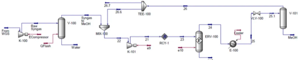
As already deeply discussed by Bozzano and Manenti [13], nowadays different processes are available for methanol synthesis operating in a wide range of pressures of temperatures. For this work, the methanol production process is simulated using an Aspen HYSYS flowsheet provided by Pellegrini et al. [53] that operates at 150 bar. The gases leave the reactor at 270 °C. In addition, a compression section is needed because methanol process operates at higher pressure compared with the one of coal gasification and amine wash units. For this reason, a compressor and a flash unit, that allows to separate the condensed water, are included in the Aspen HYSYS simulation. The reactions involved in the methanol synthesis reactor are:
2 3
CO+2H =CH OH (3)
2 2 2
CO +H =CO + H O (4)
The overall process is exothermic and so a cooling system is needed on methanol reactor. The heat recovered from the reactor effluent and the heat released by the reaction are used to produce steam for the reboilers of the subsequent separation section [54]. The unreacted gases and the product mixture are separated by cooling and expansion to about 74 bar with a recycle split factor equal to 100% in order to maximize the methanol production. The distillation column, used to separate the unconverted syngas [55], is here considered as a splitter, in order to reduce the simulation efforts. Figure 7 shows the process flow diagram of the methanol synthesis loop.
Figure 7. Process flow diagram of methanol reaction section
RESULTS AND DISCUSSION
The evaluation of the potentiality of the AG2S technology application on Coal to Methanol (CTM) process, is limited by the size of methanol production plant. For this reason a CTM plant of 600 kton/year of methanol (75 ton/hr based on 8,000 hr/year) is here considered for simulation purposes. The coal feed required is 180.8 ton/hr and the oxygen feed is 3,307 kmol/hr and the remaining inlet is steam [2]. According to the stream numbers of Figure 2, the simulation results both of the traditional CTM process and of the novel one using the AG2S technology are reported in the next paragraph.
and Environment Systems Volume 6, Issue 1, pp 210-226 Coal gasification
Sulcis coal [56] was chosen as a possible and interesting feedstock for the plant, due to its high sulfur content (about 6 %wt) which can provide a reduction of CO2 by H2S
during the gasification process [30]. Table 1 reports the ultimate analysis of Sulcis coal, carried out at Sotacarbo laboratories according to the international standards, together with the coal characterization in terms of the three reference components (COAL1, COAL2 and COAL3), according to the coal devolatilization model proposed by Sommariva et al. [57]. Table 2 summarizes the stream property and composition of a gasifier operating at 30 bar [58]. The gasifier diameter and bed height are equal to 4.0 and 15.0 meter respectively. Model predictions are obtained by assuming 4 countercorrent reactor layers without particle discretization. It is also important to underline that the formation of H2S is not predicted but, based on previous experience, it is simply assumed
as the 80-90% of inlet sulfur [28]. Therefore, 85% of sulfur goes to H2S and the
remaining 15% exits the gasifier as ashes. This assumption will be validated as future development also in terms of kinetic gasification model. Indeed, an in-deep comprehension of the phenomena that lead to the formation of H2S could be help full in
order to optimise the operation condition for this component production. Moreover, organosulfur species like COS and CS2 will be correctly predict.
Table 1. Ultimate analysis and coal characterization of sulcis coal
Ultimate analysis
% C % H % N % S % O Moisture Ash
Composition
[%wt] 53.17 3.89 1.29 5.98 6.75 11.51 17.31
Coal characterization in terms of reference species [33]
%COAL1 %COAL2 %COAL3 Moisture Ash
Composition
[%wt] 35.08 18.05 18.05 11.51 17.31
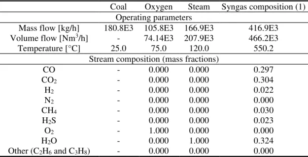
Table 2. Coal gasifier, stream properties and composition
Coal Oxygen Steam Syngas composition (1)
Operating parameters
Mass flow [kg/h] 180.8E3 105.8E3 166.9E3 416.9E3
Volume flow [Nm3/h] - 74.14E3 207.9E3 466.2E3
Temperature [°C] 25.0 75.0 120.0 550.2
Stream composition (mass fractions)
CO - 0.000 0.000 0.297 CO2 - 0.000 0.000 0.304 H2 - 0.000 0.000 0.022 N2 - 0.000 0.000 0.000 CH4 - 0.000 0.000 0.030 H2S - 0.000 0.000 0.023 O2 - 1.000 0.000 0.000 H2O - 0.000 1.000 0.324 Other (C2H6 and C3H8) - 0.000 0.000 0.000
The over prediction of outlet water is possibly due to an underestimation of the catalytic effect of ash, as already discussed and explained in Bassani et al. [30]. The peak temperature is about 1,097 °C.
and Environment Systems Volume 6, Issue 1, pp 210-226 Amine wash units
Table 3 shows the simulation results and the main operative parameters of MDEA wash units for the traditional CTM process, whereas Table 4 reports the corresponding results of the novel CTM process with the AG2S technology.
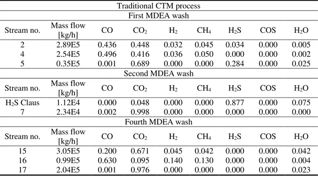
Table 3. Simulation results of amine wash units (traditional CTM): stream compositions (mass fractions)
Traditional CTM process First MDEA wash Stream no. Mass flow
[kg/h] CO CO2 H2 CH4 H2S COS H2O
2 2.89E5 0.436 0.448 0.032 0.045 0.034 0.000 0.005
4 2.54E5 0.496 0.416 0.036 0.050 0.000 0.000 0.002
5 0.35E5 0.001 0.689 0.000 0.000 0.284 0.000 0.025
Second MDEA wash Stream no. Mass flow
[kg/h] CO CO2 H2 CH4 H2S COS H2O
H2S Claus 1.12E4 0.000 0.048 0.000 0.000 0.877 0.000 0.075
7 2.34E4 0.002 0.998 0.000 0.000 0.000 0.000 0.000
Fourth MDEA wash Stream no. Mass flow
[kg/h] CO CO2 H2 CH4 H2S COS H2O
15 3.05E5 0.200 0.671 0.045 0.042 0.000 0.000 0.042
16 0.99E5 0.630 0.095 0.140 0.130 0.000 0.000 0.004
17 2.04E5 0.001 0.976 0.000 0.000 0.000 0.000 0.023
Table 4. Simulation results of amine wash units (novel CTM process with AG2S technology): stream compositions (mass fractions)
Novel CTM Process with AG2S technology First MDEA wash unit
Stream no. Mass flow
[kg/h] CO CO2 H2 CH4 H2S COS H2O
2 2.89E5 0.436 0.448 0.032 0.045 0.034 0.000 0.005
4 2.54E5 0.496 0.416 0.036 0.050 0.000 0.000 0.002
5 0.35E5 0.001 0.689 0.000 0.000 0.284 0.000 0.025
Second MDEA wash unit Stream no. Mass flow
[kg/h] CO CO2 H2 CH4 H2S COS H2O
6 1.65E4 0.000 0.378 0.000 0.000 0.596 0.000 0.027
7 1.79E4 0.003 0.986 0.000 0.000 0.000 0.000 0.010
Third MDEA wash unit Stream no. Mass flow
[kg/h] CO CO2 H2 CH4 H2S COS H2O
12 1.39E4 0.085 0.467 0.003 0.000 0.425 0.007 0.012
13 0.81E4 0.000 0.247 0.000 0.000 0.725 0.000 0.028
14 0.58E4 0.204 0.775 0.008 0.000 0.000 0.000 0.013
Fourth MDEA wash unit Stream no. Mass flow
[kg/h] CO CO2 H2 CH4 H2S COS H2O
15 3.15E5 0.197 0.675 0.044 0.041 0.000 0.000 0.043
16 1.01E5 0.631 0.096 0.141 0.131 0.000 0.000 0.002
and Environment Systems Volume 6, Issue 1, pp 210-226
As shown in Figure 2 and by the results of Table 3 and 4, first MDEA wash unit is the same for the two processes. The second MDEA wash unit shows some differences. In the traditional process, this wash unit aims to completely separate H2S from CO2 in
order to send only H2S, with a little amount of CO2 to the Claus process. On the other side,
the novel process requires an optimal ratio between H2S and CO2. According to previous
experiences, the Claus process is not directly simulated and we simply assume that H2S is
completely converted into sulfur and water [59]. Finally, the fourth amine wash shows a higher treated mass flow rate in the novel process. This is simply due to the extra syngas produced by AG2S technology.
Acid Gas to Syngas section
As already mentioned, AG2S™ technology allows to convert CO2 producing an
additional amount of syngas. Table 5 shows the predicted simulation results. The RTF works at atmospheric pressure with an inlet oxygen mass flow rate of 3,650 kg/h. According to our previous work [30], a residence time between 1-1.5 s is required in the furnace, where the temperature reaches 1, 250 °C. In the same way, the WHB is designed to quench the thermal reactor effluent, in order to prevent any possible recombination effect (e.g. hydrogen and sulfur into H2S), which have been proven to be significant
during a relatively slow cooling process [60]. For this reason, the residence time is set to 0.3 s.
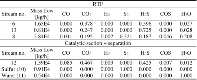
Table 5. AG2S technology simulation results: stream compositions (mass fractions)
RTF Stream no. Mass flow
[kg/h] CO CO2 H2 S2 H2S COS H2O
6 1.65E4 0.000 0.378 0.000 0.000 0.596 0.000 0.027
13 0.81E4 0.000 0.247 0.000 0.000 0.725 0.000 0.028
8 2.84E4 0.041 0.195 0.002 0.321 0.187 0.046 0.208
Catalytic section + separation Stream no. Mass flow
[kg/h] CO CO2 H2 S2 H2S COS H2O
12 1.39E4 0.085 0.467 0.003 0.000 0.425 0.007 0.012
Sulfur (10) 0.91E4 0.000 0.000 0.000 1.000 0.000 0.000 0.000
Water (11) 0.54E4 0.000 0.000 0.000 0.000 0.000 0.000 1.000
The inlet ratio H2S/CO2 to the regenerative thermal furnace, deriving from mixing
stream 6 and 13, is equal to about 2.5. This value is higher than the stoichiometric one and is a suitable starting point. However, it is not the optimal one because there is unconverted CO2 in the outlet stream (14). This lead to an outlet ratio between H2 and CO
that is equal to 0.5 instead of 1 derived by reaction (1). For sure, a future study on the inlet optimal ratio will be conducted in order to increase the yield of this process. Another key point is that the recycle mass flow rate (stream 13) is equal to a half of the inlet mass flow rate (stream 6). This means that the equipment not exceed in terms of design and dimensions. Finally, the outlet mass flow rate of H2S is equal to zero (see the streams no.
10, 11, 14). The complete conversion of H2S is reached, as in the traditional Claus
process, with an extra production of syngas.
Water Gas Shift section
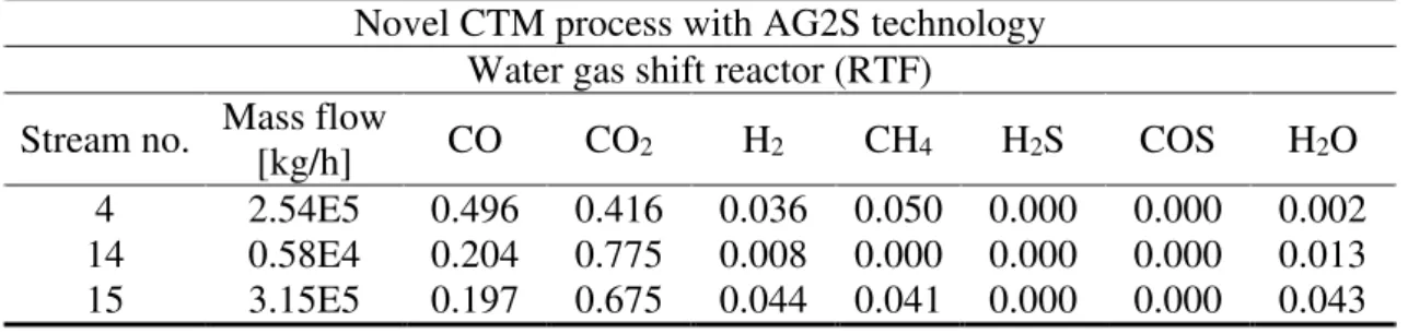
The results of the simulations of the WGS reactor are reported in Table 6 and Table 7. The inlet water is set in order to obtain a mole ratio between H2 and CO equal to about 3.2
and Environment Systems Volume 6, Issue 1, pp 210-226
in order to approach the optimal ratio suggested by Pellegrini et al. [53]. Moreover, the operative temperature of the reactor at equilibrium condition is ~270 °C.
Table 6. WGS simulation results (traditional CTM): stream compositions (mass fractions)
Traditional CTM process Water gas shift reactor (RTF) Stream no. Mass flow
[kg/h] CO CO2 H2 CH4 H2S COS H2O
4 2.54E5 0.496 0.416 0.036 0.050 0.000 0.000 0.002
15 3.09E5 0.200 0.671 0.045 0.042 0.000 0.000 0.042
Water 0.55E4 0.000 0.000 0.000 0.000 0.000 0.000 1.000
Table 7. WGS simulation results (novel CTM process with AG2S technology): stream compositions (mass fractions)
Novel CTM process with AG2S technology Water gas shift reactor (RTF)
Stream no. Mass flow
[kg/h] CO CO2 H2 CH4 H2S COS H2O
4 2.54E5 0.496 0.416 0.036 0.050 0.000 0.000 0.002
14 0.58E4 0.204 0.775 0.008 0.000 0.000 0.000 0.013
15 3.15E5 0.197 0.675 0.044 0.041 0.000 0.000 0.043
Methanol section
The Aspen Hysys simulations is performed in order to reach a methanol productivity equal to about 75 ton/h, as already mentioned before. The results of both process simulations are reported in Table 8 and Table 9. The predicted methanol productivities are 79.18 ton/h and 79.6 ton/h for traditional and novel process, respectively. It is important to notice that the simulated productivity is close to the target value and the aim to increase methanol production is reached.
Table 8. Methanol synthesis simulation results (traditional CTM): stream compositions (mass fractions)
Traditional CTM process Methanol synthesis Stream no. Mass flow
[kg/h] CO CO2 H2 CH4 H2S CH3OH H2O
16 0.99E5 0.630 0.095 0.140 0.130 0.000 0.000 0.004
18 0.84E5 0.000 0.000 0.000 0.008 0.000 0.940 0.052
Table 9. Methanol synthesis simulation results (novel CTM): stream compositions (mass fractions)
Novel process CTM process Methanol synthesis Stream no. Mass flow
[kg/h] CO CO2 H2 CH4 H2S CH3OH H2O
16 1.01E5 0.631 0.096 0.141 0.131 0.000 0.000 0.002
and Environment Systems Volume 6, Issue 1, pp 210-226
The features of the distillation train have to be taken in consideration for the global process due to the different grades of the commercialization of methanol [13].
FINAL RESULTS AND DISCUSSION
The aim of this work is to demonstrate the potentiality of AG2S technology application on the CTM process in order to reduce CO2 emissions and, at the same time,
to increase the productivity of methanol without any extra feed addition. The CO2
emissions are summarized in Table 10.
Table 10. Traditional and novel process CO2 emissions
Stream no. 7 17 Total
CO2 emissions [kg/h] 2.383E4 19.91E4 22.29E4
Stream no. 7 17 Total
CO2 emissions [kg/h] 1.762E4 20.31E4 22.07E4
According to the work of Qin et al. [25] about the life cycle assessment of coal-to-methanol chain, the emissions of CO2 per tons of methanol produced in the
traditional process, simulated in this work, is ~2.8 that is inside the expected range 2.7-3.6. Moreover, in order to prove the validity of the simulation, the highest emission is due to the water gas reactor and is equal to 89.2% of the global emissions as predict also by Qin et al. Said this, the results show a reduction of CO2 emissions equal to 1.0% and at
the same time an increasing of methanol production of ~0.5%. Another important consideration is related the type of CO2 emissions. In this work, only the direct emissions
are considered, which are, in general, only a part of the environmental impact of the process [25]. However, it is reasonable to suppose that the indirect emissions don’t increase passing from the old to the novel process configuration. Indeed, the unit operations involved in the two process are similar in terms of design and operative conditions (e.g. the coal gasifier treat the same amount of feedstock). This means that the indirect emissions remain the same with, at the same time, the increasing of the methanol production, or, from another point of view, the indirect CO2 emissions decreases with the
same methanol production due to fact that lower amount of raw materials are needed. Finally, it is important to underline the fact also AG2S process is similar to the Claus process in terms of unit operations involved. Indeed, AG2S presents a furnace, a WHB and a catalytic reactor and also the amine wash could be related to mandatory tail gas treatment unit for the Claus process [61].
CONCLUSION
This paper presents a novel effective and environmental friendly solution for industrial coal to methanol process, which allows increasing the outlet stream flowrate without using any additional primary sources. AG2S™ technology, which is the outcome of breakthrough research at Politecnico di Milano, allows to reduce the environmental impact of coal uses and, at the same time, to improve the yield of coal gasification. The basic idea is to reduce the emissions of H2S and CO2 to exploit the oxidizing capacity
of CO2 with H2S increasing production of syngas, which is the base for methanol
production. The most important results are the lower emissions of CO2 (about 0.3%) and
the greater production of methanol (about 0.5%) without any addition of primary sources, with respect to the traditional CTM process. Moreover, it is proved that a high sulfur coal charge allows a higher reduction of CO2 emissions. Implicitly this solution could lead to
other possible advantages like the possibility to exploit coal with higher sulfur content such as the Hungarian brown coal (3 to 5 %wt of S), or the Inner Mongolia-Chinese coal
and Environment Systems Volume 6, Issue 1, pp 210-226
(18 %wt of S). It is worth considering that the application of such a technology is not yet optimized in terms of feedstock and operating conditions. For instance, a possible future development could deal with the further development of the kinetic mechanisms included in the GASDS module in order to better predict the evolution of sulfur species. This could allow to optimize the H2S formation and, as a consequence, the reduction of CO2
emissions. For these reasons, given the innovative nature of the process, this technology requires more detailed analysis before it can be used on industrial plants, but this highlights that the novel process is very interesting and economically appealing.
REFERENCES
1. Alberico, E. and Nielsen, M., Towards a Methanol Economy based on Homogeneous Catalysis: Methanol to H2 and CO2 to Methanol, Chemical Communications, Vol. 51,
No. 31, pp 6714-6725, 2015, https://doi.org/10.1039/C4CC09471A
2. Liu, X., Liang, J., Xiang, D., Yang, S. and Qian, Y., A proposed Coal-to-methanol Process with CO2 capture combined Organic Rankine Cycle (ORC) for Waste Heat
recovery, Journal of Cleaner Production, Vol. 129, pp 53-64, 2016, https://doi.org/10.1016/j.jclepro.2016.04.123
3. Remediakis, I. N., Abild-Pedersen, F. and Nørskov, J. K., DFT Study of Formaldehyde and Methanol Synthesis from CO and H2 on Ni (111), The Journal of Physical
Chemistry B, Vol. 108, No. 38, pp 14535-14540, 2004,
https://doi.org/10.1021/jp0493374
4. Bansode, A. and Urakawa, A., Towards full One-pass conversion of Carbon Dioxide to Methanol and Methanol-derived Products, Journal of Catalysis, Vol. 309, pp 66-70, 2014, https://doi.org/10.1016/j.jcat.2013.09.005
5. Einaga, H., Yamakawa, T. and Shinoda, S., Synthesis of Acetic Acid from Methanol alone by Homogeneous Metal Complex Catalyst, Part II, Journal of Molecular Catalysis
A: Chemical, Vol. 97, No. 1, pp 35-40, 1995,
https://doi.org/10.1016/1381-1169(94)00073-5
6. Haro, P., Ollero, P., Perales, A. V. and Gómez-Barea, A., Thermochemical Biorefinery based on Dimethyl Ether as Intermediate: Technoeconomic assessment, Applied Energy, Vol. 102, pp 950-961, 2013, https://doi.org/10.1016/j.apenergy.2012.09.051
7. Vancoillie, J., Demuynck, J., Sileghem, L., Van De Ginste, M., Verhelst, S., Brabant, L. and Van Hoorebeke, L., The Potential of Methanol as a Fuel for Flex-fuel and dedicated Spark-ignition Engines, Applied Energy, Vol. 102, pp 140-149, 2013, https://doi.org/10.1016/j.apenergy.2012.05.065
8. Stelmachowski, M. and Nowicki, L., Fuel from the Synthesis Gas ‒ the Role of Process Engineering, Applied Energy, Vol. 74, No. 1-2, pp 85-93, 2003, https://doi.org/10.1016/S0306-2619(02)00134-4
9. Lange, J.-P., Methanol Synthesis: A Short Review of Technology Improvements,
Catalysis Today, Vol. 64, No. 1-2, pp 3-8, 2001,
https://doi.org/10.1016/S0920-5861(00)00503-4
10. Manenti, F., Cieri, S., Restelli, M. and Bozzano, G., Dynamic modeling of the Methanol Synthesis Fixed-bed Reactor, Computers & Chemical Engineering, Vol. 48, pp 325-334, 2013, https://doi.org/10.1016/j.compchemeng.2012.09.013
11. Ahouari, H., Soualah, A., Le Valant, A., Pinard, L., Magnoux, P. and Pouilloux, Y., Methanol Synthesis from CO2 Hydrogenation over Copper based Catalysts,
Reaction Kinetics, Mechanisms and Catalysis, Vol. 110, No. 1, pp 131-145, 2013,
https://doi.org/10.1007/s11144-013-0587-9
12. Al-Kalbani, H., Xuan, J., García, S. and Wang, H., Comparative Energetic assessment of Methanol production from CO2: Chemical versus Electrochemical Process,
and Environment Systems Volume 6, Issue 1, pp 210-226
13. Bozzano, G. and Manenti, F., Efficient Methanol Synthesis: Perspectives, Technologies and Optimization Strategies, Progress in Energy and Combustion Science, Vol. 56, pp 71-105, 2016, https://doi.org/10.1016/j.pecs.2016.06.001
14. Chen, C.-J., Hung, C.-I. and Chen, W.-H., Numerical Investigation on Performance of Coal Gasification under Various Injection Patterns in an entrained Flow Gasifier,
Applied Energy, Vol. 100, pp 218-228, 2012,
https://doi.org/10.1016/j.apenergy.2012.05.013
15. Ahmed, I. and Gupta, A., Syngas yield during Pyrolysis and Steam Gasification of
Paper, Applied Energy, Vol. 86, No. 9, pp 1813-1821, 2009,
https://doi.org/10.1016/j.apenergy.2009.01.025
16. Manenti, F., Cieri, S. and Restelli, M., Considerations on the Steady-state modeling of Methanol Synthesis Fixed-bed Reactor, Chemical Engineering Science, Vol. 66, No. 2, pp 152-162, 2011, https://doi.org/10.1016/j.ces.2010.09.036
17. Li, H., Hong, H., Jin, H. and Cai, R., Analysis of a feasible Polygeneration System for Power and Methanol Production taking Natural Gas and Biomass as Materials,
Applied Energy, Vol. 87, No. 9, pp 2846-2853, 2010,
https://doi.org/10.1016/j.apenergy.2009.07.001
18. Pino, L., Vita, A., Laganà, M. and Recupero, V., Hydrogen from Biogas: Catalytic Tri-reforming Process with Ni/La Ce O mixed Oxides, Applied Catalysis B:
Environmental, Vol. 148, pp 91-105, 2014, https://doi.org/10.1016/j.apcatb.2013.10.043
19. Vita, A., Cristiano, G., Italiano, C., Pino, L. and Specchia, S., Syngas Production by Methane Oxy-steam reforming on Me/CeO2 (Me = Rh, Pt, Ni) Catalyst lined on
Cordierite Monoliths, Applied Catalysis B: Environmental, Vol. 162, pp 551-563, 2015, https://doi.org/10.1016/j.apcatb.2014.07.028
20. Lior, N., Energy Resources and use: The Present Situation and Possible Paths to the Future, Energy, Vol. 33, pp 842-857, 2008, https://doi.org/10.1016/j.energy.2007.09.009 21. Man, Y., Yang, S., Zhang, J. and Qian, Y., Conceptual design of Coke-oven Gas assisted
Coal to Olefins Process for high Energy efficiency and low CO2 emission, Applied
Energy, Vol. 133, pp 197-205, 2014, https://doi.org/10.1016/j.apenergy.2014.07.105
22. Wen, Z., Meng, F., Di, J. and Tan, Q., Technological approaches and Policy analysis of integrated Water Pollution prevention and Control for the Coal-to-methanol Industry based on best available Technology, Journal of Cleaner Production, Vol. 113, pp 231-240, 2016, https://doi.org/10.1016/j.jclepro.2015.11.077
23. Chmielniak, T. and Sciazko, M., Co-gasification of Biomass and Coal for Methanol Synthesis, Applied Energy, Vol. 74, No. 3-4, pp 393-403, 2003, https://doi.org/10.1016/S0306-2619(02)00184-8
24. Ahmed, I. and Gupta, A., Evolution of Syngas from Cardboard Gasification, Applied
Energy, Vol. 86, No. 9, pp 1732-1740, 2009,
https://doi.org/10.1016/j.apenergy.2008.11.018
25. Qin, Z., Zhai, G., Wu, X., Yu, Y. and Zhang, Z., Carbon Footprint evaluation of Coal-to-methanol Chain with the Hierarchical Attribution management and Life Cycle assessment, Energy Conversion and Management, Vol. 124, pp 168-179, 2016, https://doi.org/10.1016/j.enconman.2016.07.005
26. Duan, H.-B, Fan, Y. and Zhu, L., What’s the most Cost-effective Policy of CO2 targeted
Reduction: An Application of aggregated Economic Technological Model with CCS?
Applied Energy, Vol. 112, pp 866-875, 2013,
https://doi.org/10.1016/j.apenergy.2013.01.047
27. Huaman, R. N. E. and Jun, T. X., Energy related CO2 emissions and the progress on CCS
Projects: A Review, Renewable and Sustainable Energy Reviews, Vol. 31, pp 368-385, 2014, https://doi.org/10.1016/j.rser.2013.12.002
28. Maffei, T., Sommariva, S., Ranzi, E. and Faravelli, T., A predictive Kinetic Model of Sulfur release from Coal, Fuel, Vol. 91, No. 1, pp 213-223, 2012, https://doi.org/10.1016/j.fuel.2011.08.017
and Environment Systems Volume 6, Issue 1, pp 210-226
29. Selim, H., Gupta, A. and Al Shoaibi, A., Effect of reaction Parameters on the Quality of captured Sulfur in Claus Process, Applied Energy, Vol. 104, pp 772-776, 2013, https://doi.org/10.1016/j.apenergy.2012.12.015
30. Bassani, A., Pirola, C., Maggio, E., Pettinau, A., Frau, C., Bozzano, G., Pierucci, S., Ranzi, E. and Manenti, F., Acid Gas to Syngas (AG2S™) Technology applied to Solid Fuel Gasification: Cutting H2S and CO2 emissions by improving Syngas Production,
Applied Energy, Vol. 184, pp 1284-1291, 2016,
https://doi.org/10.1016/j.apenergy.2016.06.040
31. Manenti, F., Pierucci, S. and Molinari, L., Process for reducing CO2 and producing
Syngas, Priority Patent: PCT Application Number: WO, 15457, A1, 2015.
32. El-Melih, A., Ibrahim, S., Gupta, A. and Al Shoaibi, A., Experimental examination of Syngas recovery from Acid Gases, Applied Energy, Vol. 164, pp 64-68, 2016, https://doi.org/10.1016/j.apenergy.2015.11.025
33. Frau, C., Ferrara, F., Orsini, A. and Pettinau, A., Characterization of Several kinds of Coal and Biomass for Pyrolysis and Gasification, Fuel, Vol. 152, pp 138-145, 2015, https://doi.org/10.1016/j.fuel.2014.09.054
34. Lam, H. L., Klemeš, J. J., Kravanja, Z. and Varbanov, P. S., Software Tools overview: Process integration, modelling and optimisation for Energy saving and pollution reduction, Asia‐Pacific Journal of Chemical Engineering, Vol. 6, pp 696-712, 2011, https://doi.org/10.1002/apj.469
35. Stryjek, R. and Vera, J., PRSV: An improved Peng ‒ Robinson Equation of State for pure Compounds and Mixtures, The Canadian Journal of Chemical Engineering, Vol. 64, pp 323-333, 1986, https://doi.org/10.1002/cjce.5450640224
36. Stryjek, R. and Vera, J., PRSV ‒ An improved Peng‐Robinson Equation of State with new mixing Rules for Strongly Nonideal Mixtures, The Canadian Journal of Chemical
Engineering, Vol. 64, pp 334-340, 1986, https://doi.org/10.1002/cjce.5450640225
37. Cabiancaa, L., Bassania, A., Amarala, A. F., Rossia, F., Bozzanoa, G., Ranzia, E., Telenb, D., Logistb, F., Van Impeb, J. and Manenti, F., GASDS: A Kinetic-based Package for Biomass and Coal Gasification, Chemical Engineering, Vol. 50, 2016. 38. Sommariva, S., Maffei, T., Migliavacca, G., Faravelli, T. and Ranzi, E., A Predictive
Multi-step Kinetic Model of Coal devolatilization, Fuel, Vol. 89, No. 2, pp 318-328, 2010, https://doi.org/10.1016/j.fuel.2009.07.023
39. Corbetta, M., Bassani, A., Manenti, F., Pirola, C., Maggio, E., Pettinau, A., Deiana, P., Pierucci, S. and Ranzi, E., Multi-scale Kinetic modeling and Experimental investigation of Syngas production from Coal Gasification in Updraft Gasifiers, Energy & Fuels, Vol. 29, No. 6, pp 3972-3984, 2015, https://doi.org/10.1021/acs.energyfuels.5b00648 40. Ranzi, E., Faravelli, T. and Manenti, F., Chapter One-Pyrolysis, Gasification, and
Combustion of Solid Fuels, Advances in Chemical Engineering, Vol. 49, pp 1-94, 2016, https://doi.org/10.1016/bs.ache.2016.09.001
41. Abdulrahman, R. and Sebastine, I., Natural Gas sweetening Process Simulation and Optimization: A Case Study of Khurmala Field in Iraqi Kurdistan Region, Journal of
Natural Gas Science and Engineering, Vol. 14, pp 116-120, 2013,
https://doi.org/10.1016/j.jngse.2013.06.005
42. Manenti, F., Papasidero, D., Bozzano, G. and Ranzi, E., Model-based optimization of Sulfur Recovery Units, Computers & Chemical Engineering, Vol. 66, pp 244-251, 2014, https://doi.org/10.1016/j.compchemeng.2014.01.019
43. Lim, H.-W., Park, M.-J., Kang, S.-H., Chae, H.-J., Bae, J. W. and Jun, K.-W., Modeling of the Kinetics for Methanol Synthesis using Cu/ZnO/Al2O3/ZrO2 Catalyst: Influence of
Carbon Dioxide during Hydrogenation, Industrial & Engineering Chemistry Research, Vol. 48, pp 10448-10455, 2009, https://doi.org/10.1021/ie901081f
44. Gupta, A., Ibrahim, S. and Al Shoaibi, A., Advances in Sulfur Chemistry for treatment of Acid Gases, Progress in Energy and Combustion Science, Vol. 54, pp 65-92, 2016, https://doi.org/10.1016/j.pecs.2015.11.001
and Environment Systems Volume 6, Issue 1, pp 210-226
45. Manenti, F., Papasidero, D., Frassoldati, A., Bozzano, G., Pierucci, S. and Ranzi, E., Multi-scale modeling of Claus Thermal Furnace and Waste Heat Boiler using detailed Kinetics, Computers & Chemical Engineering, Vol. 59, pp 219-225, 2013, https://doi.org/10.1016/j.compchemeng.2013.05.028
46. Ranzi, E., Frassoldati, A., Grana, R., Cuoci, A., Faravelli, T., Kelley, A. and Law, C., Hierarchical and Comparative Kinetic modeling of Laminar Flame Speeds of Hydrocarbon and oxygenated Fuels, Progress in Energy and Combustion Science, Vol. 38, No. 4, pp 468-501, 2012, https://doi.org/10.1016/j.pecs.2012.03.004
47. Manenti, F., Papasidero, D. and Ranzi, E., Revised Kinetic Scheme for Thermal Furnace of Sulfur Recovery Units, Chemical Engineering Transactions, Vol. 32, pp 1185-1290, 2013.
48. Frassoldati, A., Faravelli, T. and Ranzi, E., Kinetic modeling of the Interactions between NO and Hydrocarbons at high Temperature, Combustion and Flame, Vol. 135, No. 1-2, pp 97-112, 2003, https://doi.org/10.1016/S0010-2180(03)00152-4
49. Rhodes, C., Riddel, S. A., West, J., Williams, B. P. and Hutchings, G. J., The low-temperature hydrolysis of Carbonyl Sulfide and Carbon Disulfide: A Review,
Catalysis Today, Vol. 59, No. 3-4, pp 443-464, 2000,
https://doi.org/10.1016/S0920-5861(00)00309-6
50. Smith, R., Loganathan, M. and Shantha, M. S., A Review of the Water Gas Shift Reaction Kinetics, International Journal of Chemical Reactor Engineering, Vol. 8, No. 1, 2010, https://doi.org/10.2202/1542-6580.2238
51. Chen, W.-H., Lin, M.-R., Jiang, T. L. and Chen, M.-H., Modeling and Simulation of Hydrogen Generation from high-temperature and low-temperature Water Gas Shift Reactions, International Journal of Hydrogen Energy, Vol. 33, No. 22, pp 6644-6656, 2008, https://doi.org/10.1016/j.ijhydene.2008.08.039
52. Basile, A., Chiappetta, G., Tosti, S. and Violante, V., Experimental and Simulation of both Pd and Pd/Ag for a Water Gas Shift Membrane Reactor, Separation and
Purification Technology, Vol. 25, No. 1-3, pp 549-571, 2001,
https://doi.org/10.1016/S1383-5866(01)00168-X
53. Pellegrini, L. A., Soave, G., Gamba, S. and Langè, S., Economic analysis of a combined Energy-methanol Production Plant, Applied Energy, Vol. 88, No. 12, pp 4891-4897, 2011, https://doi.org/10.1016/j.apenergy.2011.06.028
54. Ravaghi-Ardebili, Z. and Manenti, F., Unified modeling and feasibility Study of Novel Green Pathway of Biomass to Methanol/dimethylether, Applied Energy, Vol. 145, pp 278-294, 2015, https://doi.org/10.1016/j.apenergy.2015.02.019
55. Riaz, A., Zahedi, G. and Klemeš, J. J., A Review of Cleaner production Methods for the Manufacture of Methanol, Journal of Cleaner Production, Vol. 57, pp 19-37, 2013, https://doi.org/10.1016/j.jclepro.2013.06.017
56. Pettinau, A., Orsini, A., Calì, G. and Ferrara, F., The Sotacarbo Coal gasification Experimental Plant for a CO2-free Hydrogen Production, International Journal of
Hydrogen Energy, Vol. 35, No. 18, pp 9836-9844, 2010,
https://doi.org/10.1016/j.ijhydene.2009.10.024
57. Sommariva, S., Grana, R., Maffei, T., Pierucci, S. and Ranzi, E., A Kinetic approach to the Mathematical Model of Fixed bed Gasifiers, Computers & Chemical Engineering, Vol. 35, No. 5, pp 928-935, 2011, https://doi.org/10.1016/j.compchemeng.2011.01.036 58. Zheng, L. and Furinsky, E., Comparison of Shell, Texaco, BGL and KRW Gasifiers as
Part of IGCC Plant Computer Simulations, Energy Conversion and Management,
Vol. 46, No. 11-12, pp 1767-1779, 2005,
https://doi.org/10.1016/j.enconman.2004.09.004
59. Signor, S., Manenti, F., Grottoli, M. G., Fabbri, P. and Pierucci, S., Sulfur Recovery Units: Adaptive Simulation and Model Validation on an Industrial Plant, Industrial &
Engineering Chemistry Research, Vol. 49, No. 12, pp 5714-5724, 2010,
and Environment Systems Volume 6, Issue 1, pp 210-226
60. Manenti, G., Papasidero, D., Manenti, F., Bozzano, G. and Pierucci, S., Design of SRU Thermal Reactor and Waste Heat Boiler considering Recombination Reactions,
Procedia Engineering, Vol. 42, pp 376-383, 2012,
https://doi.org/10.1016/j.proeng.2012.07.429
61. Al Wahedi, Y., Torres, A. I., Al Hashimi, S., Dowling, N. I., Daoutidis, P. and Tsapatsis, M., Economic assessment of Temperature swing adsorption Systems as Claus Tail Gas Clean up units, Chemical Engineering Science, Vol. 126, pp 186-195, 2015, https://doi.org/10.1016/j.ces.2014.12.015
Paper submitted: 15.05.2017 Paper revised: 11.09.2017 Paper accepted: 12.09.2017

![Figure 3. Multiscale nature and structure of a countercurrent coal gasifier [40]](https://thumb-eu.123doks.com/thumbv2/123dokorg/8331939.132548/4.892.203.725.253.576/figure-multiscale-nature-structure-countercurrent-coal-gasifier.webp)