Introducing NPXLab 2010: a tool for the analysis and
optimization of P300 based Brain-Computer
Interfaces
Luigi Bianchi, Lucia Rita Quitadamo, Manuel
Abbafati, Maria Grazia Marciani
Department of Neuroscience“Tor Vergata” University Rome, Italy
Luigi Bianchi, Lucia Rita Quitadamo
Centro di Biomedicina Spaziale“Tor Vergata” University Rome, Italy
Luigi Bianchi, Lucia Rita Quitadamo, Maria Grazia
Marciani
Neuroelectrical Imaging and BCI Laboratory
Fondazione Santa Lucia
Rome, Italy
Giovanni Saggio
Department of Electronic Engineering “Tor Vergata” University
Rome, Italy
Abstract— Brain-Computer Interfaces (BCI) are emerging as a
powerful tool for providing an alternative way of communication and environment control to severely disabled people. Among these systems, P300-based BCIs are widely diffused as they are easy to manage and do not require a training for the subjects. These systems, however, are still too slow so that they are actually used only by those patients that are unable to control any muscle. It is possible to improve their performances, but many different analyses need to be performed. Here a set of tools are described for the analysis and optimization of this class of BCI protocols that allow increasing the performances of such systems.
Keywords- BCI, NPX Lab, P300, Analysis
I. INTRODUCTION
RAIN Computer Interface (BCI) systems allow severely disabled people to communicate without the need of using the classical pathways of nerves and muscles. Unfortunately, many patients are unable to express their intents to the external world after a severe disablement caused by diseases such as sclerosis, or traumas, strokes, etc. [1] and suffer from the locked-in syndrome. In some ways, brain signals (which reflect some user intents) are acquired and processed to trigger switches and perform some actions.
While there are many different kinds of BCIs, which make use of different brain signals and extract signals features in different ways, the functional model of a BCI is well defined.
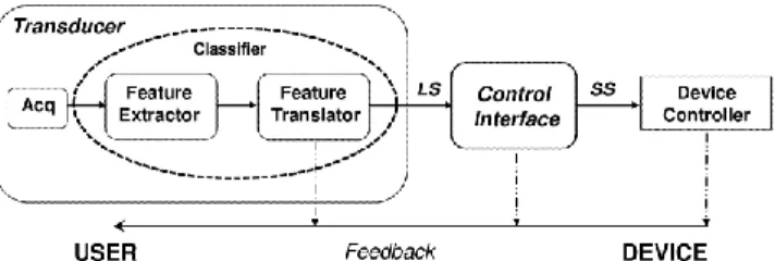
To have a vision on the structure of a BCI system, its functional model, that is widely accepted among the BCI community ([2], [3]), is now reported (Fig.1).
There are two main functional blocks which form a BCI system: the Transducer (TR) and the Control Interface (CI). The TR is responsible of the acquisition, preprocessing, analysis of brain signals and their translation into some
Fig. 1: Block representation of a BCI system.
Logical Symbols (LSs) by means of some classifiers. For example one is asked to perform 4 different tasks (e.g. imagine moving the left arm, imagine moving the right arm, performing a mental computation and mentally reproduce a nursery rhyme) and the system should recognize which of them was performed by the user. In this case the logical alphabet is formed by 4 logical symbols, each of them bound to one among the 4 mental tasks. This is possible because electroencephalographic (EEG) signals varies according to the four tasks, so that changes can be detected by some special classifiers which have been previously trained.
LSs constitute the input to the Control Interface (CI) which translates them or sequences of them into Semantic Symbols (SSs). SSs are then matched into commands towards external peripherals. In this way it is possible, for example, to command the opening of a door as a consequence of a sequence of mental tasks, such as imagining a mental computation and then a nursery rhyme.
It is then possible to bind some well defined mental activities to specific actions directed towards the environment and a user can activate switches or select letters or icons on a PC screen that allow him to communicate.
Among the different BCI protocols, those which are based on the P300 component are gaining great interest, because
they are easy to implement, require very little training (few minutes might be sufficient) and can generate a bit-rate of about 20 bits per minute, which is compatible with those of other non-invasive BCI techniques (e.g. mu-rhythm).
The P300 response is evoked after the presentation of an oddball sequence of stimulations: rare (target) events are presented to the subject, embedded in a set of frequent (non target) events; if the subject is focusing on the rare events, a positive response is evoked in his EEG after 300 ms from their presentation, the P300. In the BCI case, if a P300 component is detected after stimulation, then it is possible, with some margin of error, to state that the subject was attending to that stimulus, otherwise he was not attending at it. Usually, as the SNR ratio is very low, it is necessary to average some responses (e.g. 10) evoked by the same class of stimuli.
In this way, by detecting the events which generate the P300, it is possible to infer which are the intents the subject wants to communicate. The most widely diffused P300 protocol in the BCI research field is based on a speller constituted by a 6 by 6 matrix of 36 symbols [4], disposed as in Fig. 2. The subject, then, has to focus on the symbol he wants to communicate; then the 6 rows and 6 columns of the matrix begin to flash with a certain inter-stimulus interval (ISI) and the subject has to count how many times the desired character flash. The rows and columns which do not contain the selected character constitute the frequent events, or the non-targets.
The six rows and six columns constitute the 12 LSs which the Transducer deals with. Only on one row and one column the P300 is elicited, so, by mean of a classifier, it is possible to determine which character the subject was focusing on, that is the character found after the intersection of the target row and the target column. The 36 characters in the matrix constitute the SSs.
Fig. 2: The matrix with the 36 SSs.
A lot of papers in the literature deal with P300-based BCIs [4, 5, 6, 7, 8, 9, 10], everyone addressing different optimizing aspects of them. The aim of this paper is to illustrate a tool for analyzing P300 data in BCI protocols. The free version of the software makes use of a Stepwise Linear Discriminant Analysis (SWLDA) classifier (for details about this classifier, see [10]) even if it is possible to test other ones.
The accuracies of the classification are computed as well as the efficiency, by mean of the metric proposed in [11], where it has been demonstrated that this indicator is a reliable indicator of the performances of real BCI systems.
II. MATERIALS AND METHODS
A. The NPX Lab Suite
The NPX Lab suite is a collection of tools that allow reviewing and analyzing a wide range of electrophysiological data. Many software modules have been developed and described, based on the NPX file format (NeuroPhysiological data in XML, [12]) and build on top of the Body Language Framework (BF++ [13]), which is a set of libraries and tools for the analysis and optimization of BCI systems.
The NPX file format was designed to be flexible, extensible and actually has been used to store EEG, electromyographic (EMG), magnetoencephalographic (MEG) or Independent Component Analysis (ICA) signals.
To take full advantage from the NPX Lab suite one has to work with the NPX file format because some file formats do not allow storing all the necessary information (e.g. ICA weights). A dedicate tool (the FileConverter) allows to convert many different file formats into NPX. Supported file formats are EDF, GDF, BCI2000, EBNeuro, Neuroscan, BrainVision and ASCII.
Most of the tools presented in this paper can be freely
downloaded from the laboratory website
(http://www.brainterface.com). Among these modules the Event Related Potentials (ERP) module and the P3Classifier module can be used to analyze P300 based BCI data.
All of them have been implemented in C++ programming language and most of them are actually available for the Microsoft Win32 platform only.
B. The ERP Module
The ERP module was designed for having a dynamic, fast and flexible way of visualizing and analyzing averages computed from an EEG, EMG, MEG or ICA data file. A virtually unlimited number of averages can be computed and maintained in memory while a single EEG file is open and it is possible to quickly switch among them. It is also possible to compare two of them, even statistically.
The main features of the ERP module are:
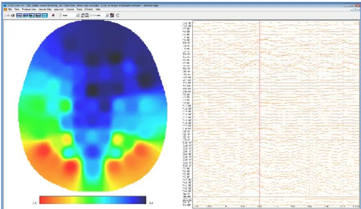
1) Computation and visualization of averages (and their standard deviations) according to many different strategies, including 2-D (Fig. 3) and 3-D mapping and cartooning mode.
2) Spectral analysis, through a flexible FFT engine, which includes power, amplitude, coherence and Standard Deviation computation, t-test statistics (Fig.4).
Fig. 4: The Main Spectral view. Spectra from 20 different sensors were computed from two different conditions (e.g. frequent and rare in P300 protocols) and plotted in two different colors (red and blue lines) for an easy and fast comparison. Spectra can be exported in several different ways.
3) Statistical analysis, to compare different averages and visualize, in a highly intuitive way, when and where two ERPs are statistically different (Fig. 5).
Fig. 5: The comparison among two different averages (frequent vs. rare in P300 protocols). Differences among the two averages are plotted. Green bubbles represent statistical significance (t-test) in their difference: the larger the bubbles, the lower the p-value. The test is computed for every channel and for every instant, so that it is possible to see when and where the two responses are different. Only values of p below 0.05 are represented, so that when there is a green bubble the difference among the two averages is statistically significant (p < 0.05).
All these functionalities can be employed to instruct the classifiers to select the most suitable sensors and time intervals to be used in real applications: one is usually interested in selecting just a limited set of features which characterize the differences among the two evoked signals (responses to rare vs. frequent stimuli). This will improve the overall accuracy of the classifiers and reduce the probability of overlearning, which might occur when the number of features (e.g. samples) is too high with respect to the number of trials used for the training of the classifiers.
C. The P3 Classifier Module
Once one has determined the most sensitive signals and more suitable time intervals to analyze (e.g. those who maximize the size of the green bubbles in the ERP module), then he can start to use the P3Classifier module. This module is responsible for the offline analysis of the brain signals and generates a LS which represents the output of the classification process. In other words, it implements a sort of offline Transducer, where the acquisition stage is substituted by a file driver. As in the offline analysis it is possible to know which was the desired LS and the classified one, it can also be easy to compute the number of correct and wrong classifications, thus providing a way for evaluating the performances of a specific configuration (in terms of classifier and data used for the classification).
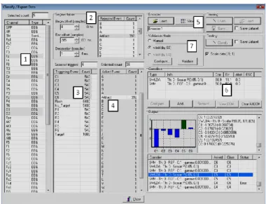
In Fig. 6 it is shown the main form of this tool.
Fig. 6: The main classifiers view. See text for details.
There are seven main regions, numbered in the figure, which can be used to train and test the classifiers. The seven regions are respectively:
1) The Channel selection list. In this list one can select the sensors to use for the classification. One is usually interested in finding a limited set of sensors that guarantee an adequate performance of the whole BCI system. This because the training will be generally shorter and also the preparation of the recording (EEG electrodes need to be put on the scalp with a conductive gel) will be faster.
2) The segmentation panel. In this area one can select which time interval of the evoked responses will be used by the classifier. In P300 protocols 600ms after the stimulation can be used. Some special events (e.g. Artifacts) can be used to discard a portion of the signal.
3) The Triggering Event panel. Here the LSs corresponding to the stimulations are reported. In Fig.6 the label C1,.., C6 indicate the occurrence of a flash in the six columns.
4) The Asked Event panel. In this list the semantic symbols that one wanted to communicate are indicated.
5) The Encoder panel. The CI is responsible to create a map between LSs and SSs. Once loaded, and knowing the event list stored in the file, it automatically computes what are the frequent (target) and rare (non target) stimuli.
6) The Classifiers panel. In this region one can select the classifiers to use (SWLDA and Support Vector Machine in the figure) and see their performances, according to the metric described in [11]. It is also possible to set some parameters relative to the various classifiers.
7) The Validation Mode panel. In this region one can set the way the validation is performed: for example it is possible to decide how to select the data for the training and the testing, if the results should be saved into a file etc…
The main results of the classification are displayed in the bottom right part of the form, but usually they are stored into an external file and reloaded into a spreadsheet or into other NPX Lab Suite tools to perform further processing (e.g. 2-D and 3-D topographic maps representation, performance optimization, etc…).
III. DISCUSSION AND CONCLUSION
BCI systems are gaining great interest because they allow severely disabled people to communicate and interact with the environment. There are many different classes of BCI protocols that can be used, but those based on the P300 component have the advantage of providing good performances and require little or very limited training at the same time. However, there are many areas that are still unexplored and the NPX Lab Suite can be successfully used to give an answer to many open questions: for example, which are the best sensors set that should be used? And what is the best classifier and how should it be set? What is the most relevant time interval relative to the stimulations onsets that should be used by a classifier?
The friendly and intuitive user interface of the P3Classifier allows testing a virtually unlimited number of different configurations with just few mouse clicks. In this way it is possible to tune a BCI system to every single user with very little effort and to explore new configurations and new classifiers in a very convenient way. This will represent a great advantage compared to other solutions which are based on other tools (e.g. matlab, which requires some experience and the purchase of a license) and a painless and easy approach to P300 based BCI protocols: one has usually just to convert the data from the EEG acquisition system into the NPX file format, eventually review the recording to make annotations (e.g. artifact suppression) with other tools (the EEG module) and then launch the P3Classifier to start to classify BCI data.
In the next main release of the NPX Lab Suite it will be also possible to implement and use self-build classifiers and use them online with the free Body Language framework. A tool similar to the P3Classifier will be implemented for analyzing spectral data and it will be also possible to perform online classifications with it.
All these features will make the Suite even more usable and items rich in a way that will allow researchers to concentrate their efforts on data analysis regardless of the implementation of service routines (e.g. data read and write, performance evaluation, etc..) which are already available and fully functional in a very comfortable and easy to use free set of tools.
ACKNOWLEDGMENT
This work was supported in part by the DCMC Project of the Italian Space Agency. This paper only reflects the authors’ views and funding agencies are not liable for any use that may be made of the information contained herein.
REFERENCES
[1] J. R. Wolpaw, N. Birbaumer, D. J. McFarland, G. Pfurtscheller and T.M. Vaughan, “Brain-computer interfaces for communication and control”, Clin Neurophysiol, vol. 113, no.6, pp. 767-791, Jun 2002.
[2] S. G. Mason, M. M. Jackson and G. E. Birch, “A general framework for Characterizing Studies of Brain Interface Technology”, Ann Biomed Eng, vol. 33, no. 11, pp. 1653-1670, Nov 2005.
[3] L. R. Quitadamo, M. G. Marciani, G. C. Cardarilli and L. Bianchi, “Describing different Brain-Computer Interface Systems through a unique model: a UML implementation”, Neuroinform, vol. 6, no.2, pp. 81-96, Jul 2008.
[4] E. Donchin, K. M. Spencer and R. Wijesinghe, “The Mental Prosthesis: Assessing the Speed of a P300-Based Brain-Computer Interface”, IEEE Trans Rehabil Eng, vol. 8, no. 2, pp. 174-179, Jun 2000.
[5] E. W. Sellers, A. Kübler and E. Donchin, “Brain–Computer Interface Research at the University of South Florida Cognitive Psychophysiology Laboratory: The P300 Speller”, IEEE Trans Neural Syst Rehabil Eng, vol. 14, no. 2, pp. 221-224, Jun 2006.
[6] E. W. Sellers, D. J. Krusienski, D. J. McFarland , T. M Vaughan and J. R. Wolpaw, “A P300 event-related potential brain-computer interface (BCI): the effects of matrix size and inter stimulus interval on performance”, Biol Psychol, vol. 73, no. 3, pp. 242-252, Oct 2006. [7] H. Serby, E. Yom-Tov and G. F. Inbar, “An Improved P300-Based
Brain Computer Interface”, IEEE Trans Neural Syst Rehabil Eng, vol. 13, no. 1, pp. 88-98, Mar 2005.
[8] F. Nijboer, E. W. Sellers, J. Mellinger, M. A Jordan, T. Matuz, A. Furdea, S. Halder, U. Mochty, D. J. Krusienski, T. M. Vaughan, J. R. Wolpaw, N. Birbaumer and A. Kübler, “A P300-based brain-computer interface for people with amyotrophic lateral sclerosis”, Clin Neurophisiol, vol. 119, no. 8, pp.1909-16, Aug. 2008.
[9] B. Z. Allison, J. A. Pineda, “Effects of SOA and flash pattern manipulations on ERPs, performance, and preference: implications for a BCI system”, Int J Psychophysiol, vol. 59, no. 2, pp. 127-40, Feb 2006. [10] D. J. Krusienski, E. W. Sellers, D. J. McFarland, T. M. Vaughan and J.
R. Wolpaw, “Toward enhanced P300 speller performance”, J. Neurosci Methods, vol. 167, pp. 15-21, Jan 2008.
[11] L. Bianchi, L. R. Quitadamo, G. Garreffa, G. C. Cardarilli and M. G. Marciani, “Performances Evaluation and Optimization of Brain-Computer Interface Systems in a copy spelling task”, IEEE Trans Neural Syst Rehabil Eng, vol. 15, no. 2, pp. 207-216, Jun 2007. [12] L. Bianchi, L.R. Quitadamo, M.G. Marciani, B. Maraviglia, M.
Abbafati, G. Garreffa. “How the NPX data format handles EEG data acquired simultaneously with fMRI”, Magn Reson Imaging, vol 25(6):1011-4, Jul 2007.
[13] L. Bianchi, F. Babiloni, F. Cincotti, S. Salinari and M. G. Marciani “Introducing BF++: A C++ Framework for Cognitive Bio-Feedback Systems Design”, Methods Inf Med, vol. 42, no. 1, pp. 104-110, 2003.