Heat transfer enhancement by spinodal decomposition in micro heat
exchangers
S. Farisè, P. Poesio, and G.P. Beretta
Laboratorio di Fisica Tecnica, Università degli Studi di Brescia, Brescia, Italy
1 Introduction
During the past three decades the pursuit of denser circuit architecture has resulted in significant improvements in the performance of micro-electronic devices. These improvements have always been accompanied by a significant increase of the heat generated demanding more efficient cooling technologies. The micro-channel heat sinks are a prime contender for thermal management of high-power-density electronic components in many cutting-edge computer, aerospace and medical applications because of their unique attributes of low thermal resistance, compact dimensions, small coolant inventory, and low power requirements. Tuckerman and Pease [1] first introduced the concept of micro channel heat sink and since then several technologies have been developed to exchange heat more effectively.
An important distinction must be made between technologies that use a single-phase flow and those that use multiphase flows. Among the latter another distinction is between multiphase flows of a single constituent and flows of non-miscible phases.
Performance rises significantly using multi-phase technology. The study of boiling flows in a micro channel leads to much higher heat transfer coefficients due to the high heat of vaporization.
In Farisè et al. [2] we introduce the possibility of using spinodal mixtures to generate an evenly distributed micro agitation which increases the effective diffusivity that therefore increases the heat exchange. There are, in our opinion, several appealing features that motivate the use of spinodal mixtures for heat exchange purposes.
First of all the encouraging results shown and published in Di Fede et al. [3], Poesio et al. [4], Gat et al. [5].
Secondly the wide variety of bi and tri component spinodal mixtures allows one to find the critical temperature closer to the design parameters of the device to be cooled. Moreover, since the mixture remains liquid, there are no instabilities in the flow, no pumping problems and no pressure drop fluctuation. There is also no need to re-condense the gaseous phase.
The issue now is to understand how these
improvements in the heat exchange are penalized by the increase in pumping power needed. The latest technologies such as nano-fluids, fluids in phase change, and micro jets loose much of their appeal when we look at the pressure drop.
2 Theory
Spinodal decomposition is the spontaneous process whereby an unstable partially miscible liquid mixture relaxes toward a lower free energy (stable) equilibrium state. During this process, an initially homogeneous liquid solution of a given composition spontaneously changes from an unstable single-phase to a two-phase stable state consisting of two separated liquid phases, of different compositions, in mutual equilibrium. This is possible only if the overall Gibbs free energy of the two separated phases is lower than that of the initial single-phase mixture. When an initially homogeneous liquid mixture at high temperature is cooled rapidly across the coexistence (binodal) curve into the two-phase region, it undergoes phase segregation (demixing) either by nucleation or by spinodal decomposition. Nucleation occurs when quenching takes the system in a metastable equilibrium state (between the binodal and the spinodal curve): it is an activated process and a free energy barrier must be overcome in order to form critical nuclei that later grow and coalesce. Spinodal decomposition, instead, occurs spontaneously, without an energy barrier to overcome (the initial state is below the spinodal curve): all the concentration fluctuations are amplified regardless of their size and wavelength. If the mechanism of segregation is convection dominated, as occurs for low viscosity systems, drops move against each others under the influence of non-equilibrium capillary forces, the so-called Korteweg stresses Poesio et al. [6]. Recently, it has been shown that this self-induced disordered bulk flow can be used to increase the heat transfer rate both in a closed configuration Poesio et al. [4] and in small pipe flow Gat et al. [5] and Di Fede et al. [3]. Also numerical simulations predict a significant increase in heat transfer - Molin and Mauri [7].
C
3 Experimental set-up
We used an UCST (upper critical solution temperature) bi-component system made by a mixture of acetone and hexadecane (i.e. there is a critical temperature above which the components of the mixture are miscible in all proportions). The minimal complete miscibility temperatures, as shown in Fig.1, is 27°C and it is obtained using equal volume parts of the two components (yacn = 0.799 in mole fraction of acetone).
Experimental data on the binodal curve are from Machedo and Rasmussen [8]. The spinodal curve is estimated using a two-parameter Margules-type model, Di Fede et al. [3].
Figure 1. Miscibility-gap phase diagram for Acetone-Hexadecane mixtures.
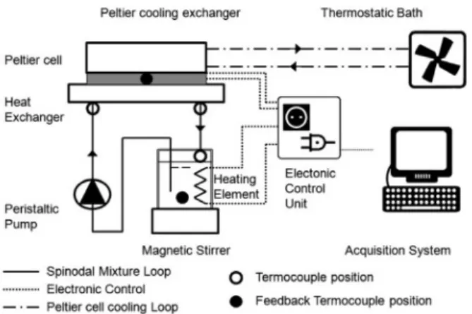
We used two different experimental set-up configurations: the first one is used to measure the heat exchange enhancement, the second one to visualize the induced convection and the macroscopic flow pattern of the two-phase flow and to measure the pressure drop. In all cases we used the critical mixture composition: 79.9% mole fraction of acetone and 21.1% of hexadecane. 3.1 Multichannel copper heat exchange setup To measure the heat transfer enhancement effect due to spinodal decomposition, we developed a closed-loop experimental set-up (Fig. 2) that allows us to pump the mixture from a hot thermostatic reservoir to the experimental test section where it is quenched by the cold pipe walls. The test section consists of a micro heat-exchanger. A Peltier cell is used to set and maintain the temperature of the cold side of the exchanger throughout the test. The temperature of the cold side of the Peltier cell is kept constant by a computer controlled PID (Proportional Integral Derivative controller) which regulates the duty cycle of the electric power supplied to the cell to keep the temperature constant. We also need a controlled temperature at the inlet of the heat exchanger that must be above 27°C. So we built and used a heating thermostat, also controlled by the PC and agitated with a
magnetic stirrer, to keep the temperature as uniform as possible and to facilitate the mixing of the mixture.
By reading the value of the duty cycle set by the PID feedback control we can estimate how much heat the hot thermostatic bath gives to the mixture reservoir to keep the temperature constant for the imposed conditions of cooling temperature and flow rate. Our experiment has been done on two different types of copper heat exchangers.
The first and most simple heat exchanger is made of nine parallel channels (0.7 mm wide, 1.5 mm tall and 72 mm long) - Fig. 3A.
The second heat exchanger - Fig. 3B - is something very similar to actual heat sinks used to cool CPU’s on PC’s motherboards. It is a compact multi-channel array (14 U-shaped channels). This too is sealed with a glass and cooled with a Peltier cell behind the channels. 3.2 Single channel pressure drop setup
In Fig. 4 is shown the set-up for heating the mixture uniformly and to make it reach the test section at a temperature higher than that of mixing, so that the spinodal decomposition occurs in the micro channel. For the uniform heating of the mixture we used a magnetic stirrer, in combination with a resistance and a type T thermocouple. This allows us to keep the temperature of the mixture constant by a PID.
To avoid that the mixture gets in the channel at a too low temperature, we wrapped around the connecting tube an electrical resistance, whose duty cycle of electrical power was controlled first manually and then using a PID control.
Next to the inlet and outlet thermocouples, we placed the input fittings of a differential pressure sensor (MPXV7002DP). This sensor has a range from -2 to 2kPa.
Figure 2. Sketch of the experimental set-up used to measure the heat exchange enhancement.
Figure 3. The two heat exchangers we tested in our experimental setup.
The mixture is pumped from the bath into the channel with a fixed flow rate by a syringe pump.
The glass microchannel is made up by two microscope slides glued together using anodic bonding (see Fig. 5). The first slide has two circular openings in which we pasted the input and output plugs, the second slide has a central groove.
While using this glass test section the cooling of the mixture in the channel took place by a flow of compressed air cooled using a plate fin heat exchanger and a water cycle, kept at low temperature by a thermostatic bath.
At both ends of the channel, we put two T-type thermocouples to acquire the inlet and outlet temperatures. Another T-type thermocouple was placed in contact with the surface of the channel. Finally there is the thermocouple placed in the mixture reservoir to constantly monitor the temperature of the hot mixture and as a feedback for the PID controller of the hot thermostatic bath.
Figure 4. Sketch of the experimental set-up used to measure the pressure drop.
Figure 5. Glass microchannel used to measure pressure drops.
4 Results
4.1 Heat exchange enhancement
We tested the multichannel exchangers with two quench temperatures of: 25°C and 20°C. With 25°C, our visualization, shows a mild spinodal decomposition; with 20°C, instead, the quench is deep enough that we do observe vigorous spinodal decomposition in the test section. Figures 5 to 9 show the heat exchanged by the pure fluids and the critical mixture.
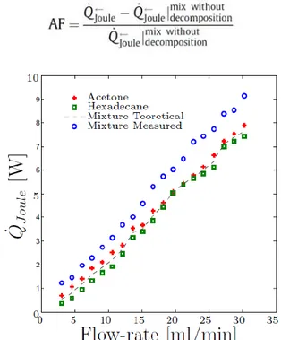
To evaluate the enhancement effect, we compute the augmentation factor defined as follows:
Figure 6. Electric power absorbed by the 9-parallel-channels heat exchanger with Tbath=35°C and TCu=25°C, 2°C quench,
mild decomposition.
Figure 7. Electric power absorbed by the 9-parallel-channel heat exchanger with Tbath=35°C and TCu=20°C, 7°C quench,
Figure 8. Electric power absorbed by the 14-U-shaped-channels heat exchanger with Tbath=35°C and TCu=25°C, 2°C quench,
mild decomposition.
Figure 9. Electric power absorbed by the 14-U-shaped-channels heat exchanger with Tbath=35°C and TCu=20°C, 7°C quench,
vigorous decomposition.
Comparing Fig. 6 with Fig. 7 and Fig. 8 with Fig. 9 shows that the enhancement effect is higher for the deeper quench (7°C in Figs. 7 and 9 versus 2°C in Figs. 6 and 8).
Figure 10 shows the augmentation factors obtained using the data in Figures 6 to 9. It shows that the heat transfer enhancement is larger at lower flow rates in the single channel. This is because as the flow rate is increased the standard convective effects overwhelm the microscopic convection induced by the spinodal decomposition.
Figure 10. Heat transfer Augmentation Factor (AF), computed from the data in Figs. 6 to 9 and plotted versus per-channel flow
rate (recall that the data in Figs. 6 and 7 refer to the 9-channel heat exchanger of Fig. 3A whereas the data in Figs. 8 and 9 to
the 14-channel heat exchanger of Fig. 3B).
4.2 Pressure drop in the glass channel
Pressure drop measurements in the single microchannel glass test section are currently under way and we can report only preliminary data.
One set of experiments focuses on pure fluids, i.e., pure acetone and pure hexadecane, entering the microchannel at a temperature of 30°C and cooled to room temperature in the set-up. We tested flow rates in the range between 0.2 and 2.5 ml/min, in order to study the relationship between pressure drop and flow rate. The data plotted in Fig.11 show a reasonable agreement with the expected linear relation between these two parameters.
Figure 11. Measured pressure drops for pure acetone and pure hexadecane in the single micro-channel. The dashed lines are
Each of the dashed lines in Fig. 11 represents the pressure drop estimates from a standard correlation for fully developed laminar flow in pipes of noncircular cross section, based on the ratio between the known viscosity of the corresponding pure component and that of pure water, and on an estimate of the hydraulic diameter based on pressure drop measurements obtained by flowing pure water in the same single channel. The agreement is good.
Figure 11. Measured pressure drops for pure acetone and pure hexadecane in the single micro-channel. The dashed lines are
obtained from the standard correlation for laminar flow. Another set of measurements focuses on the flow of the acetone-hexadecane mixture in the single channel. All these data are plotted in Fig. 12.
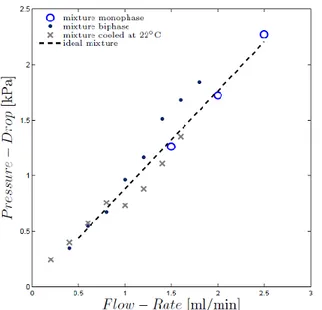
Figure 12. Measured pressure drops for the mixture at various conditions (see text).
The blue circles represent the measured pressure drops when the mixture is single-phase, obtained by setting the inlet temperature at 30°C and the outlet above 28°C, so that the mixture remains completely along the entire channel. The black dots represent the results obtained
when the mixture enters the microchannel at 25°C and exits at 22°C so that it remains two-phase along the entire channel. The data marked with the cross refer to the inlet at 30°C and the outlet at 22°C so that the mixture undergoes spinodal decomposition. Finally, the dashed line represents the standard correlation for fully developed laminar flow evaluated with a mixture viscosity estimated by a simple mole-fraction weighted average as follows
µmixture= 0.799µacetone + 0.201µhexadecane = 0.82 mPa s
We note that the vigorously quenched mixture (cross symbols) follows the ideal mixture curve until between 0.8 ml/min and 1 ml/min the pressure drops falls discontinuosly below the corresponding ideal and two-phase data. We attribute this to the onset of spinodal decomposition in the test section. As the flow rate increases, the pressure drop remains consistently lower than the fully separated two-phase data (black dots) but approaches the ideal line.
Further experiments are under way to investigate this peculiar behavior which, if confirmed, would indicate the unusual situation whereby an increase in heat transfer performance is accompanied by a reduced pressure drop.
5 Conclusions
In this paper we report preliminary experimental data on heat transfer enhancement due to spinodal decomposition in single and multi channel heat exchangers.
The values of the simplified augmentation factor defined here are higher than for the data obtained by Di Fede et al. (2011) (AFid ≈ 0.2 ÷ 0.4) with a heat
exchanger of larger hydraulic diameter (and hence a small effective quench rate), but lower than those obtained by Poesio et al. (2007) (AFid = 10) with fluid at
rest in thin vial (and a high effective quenche rate). These result follows the expected trend outlined in these previous papers and support the conclusion that the augmentation factor increases as the size of the channels and the flow rate are decreased, because the quench rate increases.
This trend is confirmed by Fig. 13 which shows all the data presented here plotted together with the data obtained by Di Fede et al. (2011) and by Poesio et al. (2007). The augmentation factor (AF) increases exponentially as the Re number decreases.
From the point of view of applications, this is an important conclusion because small sizes and low flow rates are typically characterized by small Nu numbers and can therefore benefit most from the spinodal enhancement effect.
Furthermore, if further experiments under way confirm the unespected observation that at the same time the measured pressure drop is consistently slightly reduced, the spinodal heat transfer enhancement technology becomes even more interesting and encouraging, as it would depart from all other technologies whereby the heat exchange enhancement is usually carries with it as increased pumping power as a typical side effect.
Acknowledgements
Work done under AOARD grant 104146, the Cariplo– UniBS–MIT-MechE faculty exchange program co-sponsored by Università di Brescia and the CARIPLO Foundation, Italy under grant 2008-2290, and PRIN09 “Studio sperimentale e teorico di aspetti fondamentali del miscelamento liquido-liquido”. The work of Prof. P. Poesio is sponsored by Italian-Israeli bilateral agreement.
References
1. D.B. Tuckerman and R.F.W. Pease, IEEE Electron Device Lett. EDL-2 5 126 (1981)
2. S. Farisè, A. Franzoni, P. Poesio, G.P. Beretta, Exp. Thermal and Fluid Science 42 38 (2012)
3. P. Poesio, A.M. Lezzi, G.P. Beretta, Phys. Rev. E 75 066306 (2007)
4. F. Di Fede, P. Poesio, G.P. Beretta, Int. J. Heat Mass Transfer 55 897 (2011)
5. S. Gat, N. Brauner, A. Ullman, Int. J. Heat Mass Transfer 52 1385 (2009)
6. P. Poesio, G.P. Beretta, T. Thorsen, Phys. Rev. Letters 103 064501 (2009)
7. D. Molin and R. Mauri, Phys. Fluids 19 074102 (2007)
8. E. Machedo and P. Rasmussen, DeChema Data Ser. V (part 4, 52) (1987)