for Giuliana,
”...Oh, kiss me beneath the milky twilight,
Lift your open hand,
Strike up the band and make the fireflies dance,
Silver moon’s sparkling.
So kiss me...”
for my
Parents.
Acknowledgements
In this moment, my first thought is for Giuliana, during these three years, she has supported and endured me, she has constantly encouraged me and given the desire and the strength to go forward. Even during the most diffi-cult moments, one of her sweet smile is always enough to strengthen me and start over. Years ago, I still did not met Giuliana and in a thesis I read this inscription: ”Behind every great man there is always a great woman”, then I did not understand the meaning of this phrase, but now I know what it means to have a special woman at my side. Thank you Giuliana.
Another very special thank I want to say to my parents for their constant presence and for their sacrifices to help and support me.
I have to thank my prof. Marano and Floriano who allowed me to make this PhD experience.
I want also to thank Mauro, Peppino, Fiore, Luana and Franco for each moment spent together, in a particular way a thank to my friend of ”office room” Fiore.
Another thank is for Attilio, I spent, working with him, a little period of doctorate. I find in Attilio a ”great worker” and a real person. I want say thanks also to Giuseppe, he and Attilio involved me in the ”work”, I felt me as a part of the ”group”.
Last but not least, a thought is open to all students and the people which I met during these three years of doctorate, each of them gave me something and I want to thank them.
Summary
The wireless networks, characterized by a great potential, represent an in-creasing attractive world. Via wireless connection and exploiting the wireless advantages, it is possible to eliminate the infrastructure and cabling issues re-lated to wired counterparts. An interesting aspect is the capability to install, relatively quickly, a network which is able to offer services to a wide range of users. With a wireless network, it is also possible to enrich an existing wired network or to create from scratch in a permanent or in a temporary way a new wireless architecture; related to the last advantage we can consider the useful possibility to extol the wireless capability in area affected by natural disasters. In all these cases and many others, that we do not mention, a wire-less network is certainly preferable for the ease and speed installation, the cost and the ability to easily extend the number of users.
Within the spectrum of wireless technologies, currently existing, the WiMAX technology and the IEEE 802.16 standard which defines its char-acteristics, occupies a special place. The IEEE 802.16 is a wireless technology for metropolitan area networks, created to allow access to wireless broadband. In the various versions of the protocol and subsequent corrections published, were introduced several important features, such as the possibility of using mesh network mode, which allows the creation of direct links between users. In the most recent version, IEEE 802.16e, has added the user mobility capa-bility.
This thesis summarizes the issues considered in the PhD period and re-lated to both the physical (PHY) and medium access control (MAC) layers as defined by the IEEE 802.16 standard. The study and analysis of the two protocol layers constitutes the first step to achieve our goal: we want to con-tribute to the development of WiMAX technology in order to concon-tribute to the creation of an 802.16 network architecture which is able to provide a broad variety of services to users, where each service is characterized by well-defined quality levels. The contribution of this thesis may therefore be expressed in terms of developing of channel error models (related to the physical layer) and algorithms (related to both levels of protocol) that can be a support for the
provision of quality of service. In particular, in this thesis has been examined a set of interesting challenges in WiMAX mesh scenarios as call admission control and metrics to support the route selection. Finally the various solu-tions tested and developed have been integrated into a single framework that can act as a support for the quality of service.
Contents
Acknowledgements . . . iii
Summary . . . v
List of Figures . . . xiv
List of Tables . . . xv
Acronyms . . . .xvii
1 The advent of a new technology: WiMAX . . . 1
1.1 Introduction . . . 1
1.2 IEEE 802.16 standard evolution and related documents . . . 5
1.3 An overview of MAC and PHY protocol layers . . . 8
1.3.1 MAC layer . . . 9
1.3.2 PHY layer . . . 17
1.3.3 QoS mechanisms . . . 18
1.4 A brief introduction to the addressed issues . . . 25
1.4.1 Channel error models: to improve the QoS and to make easy the systems simulations . . . 25
1.4.2 Call admission control: to improve bandwidth management . . . 26
1.4.3 Are there multiple routes? . . . 27
1.4.4 A team effort to achieve a common goal . . . 28
2 Channel error models for WiMAX scenarios . . . 29
2.1 Introduction . . . 29
2.2 Channel model: state of the art . . . 30
2.3 What we propose in this regard? . . . 32
2.4 Markov chain based models . . . 33
2.4.2 FSM (Full State Markov) . . . 35
2.4.3 HMM (Hidden Markov Model) . . . 35
2.4.4 MTA (Markov-based Trace Analysis) . . . 37
2.5 Markov chain based model performance evaluations . . . 38
2.5.1 WiMAX scenario and transmission channel implementation . . . 38
2.5.2 Simulation settings . . . 40
2.5.3 Performances Parameters . . . 42
2.5.4 Performance evaluations . . . 44
2.6 Hybrid and IWPM models: the our idea to design new generative models . . . 46
2.6.1 The Hybrid Model . . . 46
2.6.2 Instant Weighed Probability Model (IWPM) . . . 52
3 Call admission control in a mesh scenario . . . 79
3.1 Introduction . . . 79
3.2 Call Admission Control in WiMAX mesh networks: the state of the art . . . 80
3.3 GCAD: A new Call admission control algorithm . . . 81
3.3.1 Minislot number request estimation . . . 81
3.3.2 Call Admission Control Algorithm . . . 83
3.4 Simulation Scenario . . . 85
3.5 Performance evaluations . . . 88
4 A metric as routing support in a multi route mesh scenario 97 4.1 Introduction . . . 97
4.2 The state of the art . . . 98
4.3 DIM: A Delivering time based Interference Metric . . . 101
4.4 Simulation scenario . . . 103
4.5 DIM Performance evaluations . . . 105
4.6 DIEM: An improvement of DIM . . . 111
4.7 DIEM Performance evaluations . . . 112
5 A framework to support the quality of service . . . 117
5.1 Introduction . . . 117
5.2 QoS based traffic classification . . . 118
5.3 Call admission control and allocation algorithm . . . 118
5.4 MSNEA: Mini Slot Number Estimation Algorithm . . . 119
5.5 PADIEM: Priority Aware Delivering time Interference and ETT based Metric . . . 124
5.6 PSEA: Packet Size Estimation Algorithm . . . 128
5.7 Cross - Layer Framework Scheme . . . 130
5.8 Performance Evaluations . . . 132
Contents ix
References . . . 141 List of Publications . . . 147
List of Figures
1.1 A typical WiMAX scenario in PMP mode . . . 3
1.2 An example of WiMAX scenario operating in mesh mode . . . 4
1.3 IEEE 802.16 protocol stack . . . 9
1.4 MAC PDU . . . 12
1.5 Management message . . . 12
1.6 PDU classification . . . 19
1.7 Mesh frame . . . 24
2.1 Gilbert - Elliot model . . . 34
2.2 Simulation trace scansion and states sequences individuation . . . 36
2.3 Markov chain model obtained by MTA algorithm . . . 38
2.4 OFDM symbol . . . 40
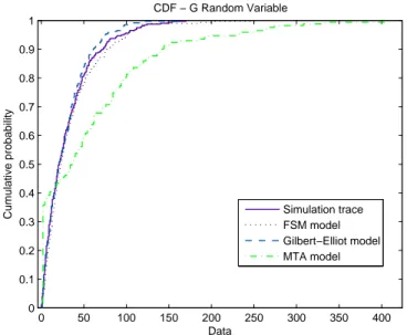
2.5 CDFs of the G random variable related to the simulation trace, FSM, the Gilbert-Elliot and MTA model . . . 45
2.6 Hybrid model flow chart . . . 47
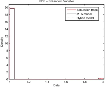
2.7 PDFs of the B random variable for the simulation trace, Hybrid and MTA model . . . 50
2.8 CDFs of the G random variable for the simulation trace, Hybrid and MTA model . . . 51
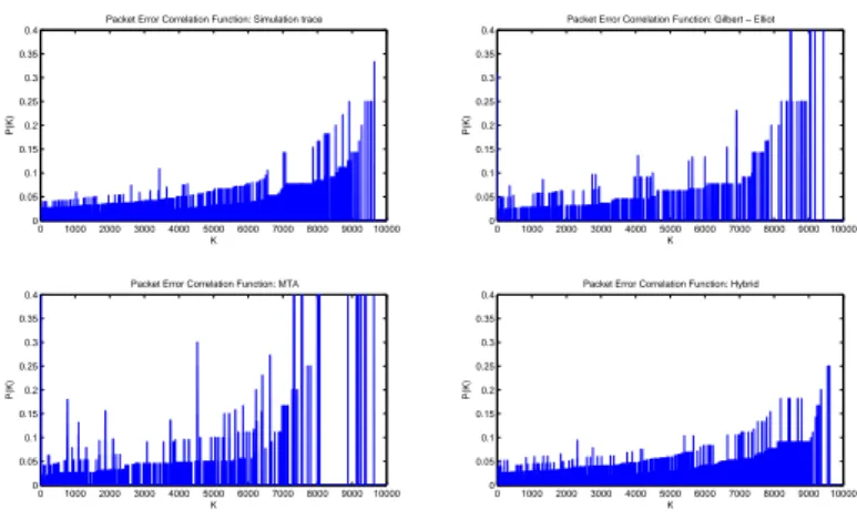
2.9 Packet error correlation functions (PECF) for the simulation trace, Gilbert Elliot, Hybrid and MTA artificial traces . . . 51
2.10 IWPM scheme . . . 53
2.11 fv,odd and fv,evenbehavior . . . 55
2.12 User speed characteristic . . . 56
2.13 Speed sampling . . . 56
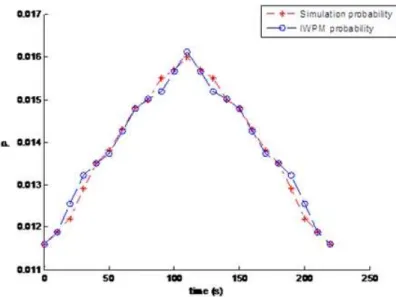
2.14 Probability of having a bad packet obtained by simulation and IWPM model . . . 57
2.15 Percentage relative error between simulation values and IWPM values vs user speed . . . 57
2.16 User speed characteristic and speed sampling . . . 58
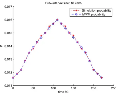
2.18 Probability of having a bad packet obtained by simulation and
IWPM model with 10 km/h sub-interval size . . . 60
2.19 Percentage relative error between simulation values and IWPM values vs user speed with 10 km/h sub-interval size . . . . 60
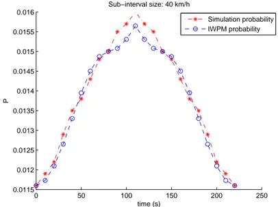
2.20 Probability of having a bad packet obtained by simulation and IWPM model with 40 km/h sub-interval size . . . 61
2.21 Percentage relative error between simulation values and IWPM values vs user speed with 40 km/h sub-interval size . . . . 61
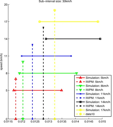
2.22 Confidence intervals and IWPM predicted values with 30km/h sub-interval size . . . 62
2.23 Confidence intervals and IWPM predicted values with 40km/h sub-interval size . . . 63
2.24 probability values obtained by simulation, by IWPM model with sin() and cos() weight function and by linear function . . . . 64
2.25 Probability to have a bad packet . . . 65
2.26 Percentage relative errors . . . 65
2.27 IWPM scheme . . . 67
2.28 Area individuated by the four sub-interval bounds . . . 69
2.29 User speed characteristic and speed sampling . . . 71
2.30 Confidences intervals and IWPM-2V predicted values . . . 72
2.31 Confidence intervals and IWPM-2V predicted values with 40km/h and 70 byte sub-intervals size . . . 73
2.32 IWPM-3V model . . . 74
2.33 A particular ”cube” (state) of the model . . . 75
3.1 Call admission control proposed algorithm . . . 84
3.2 Data subframe with minislot allocations . . . 84
3.3 Data subframe states: (a) before preemption; (b) after preemption and finally (c) after defragmentation process . . . 85
3.4 Simulated scenario . . . 85
3.5 Packet loss percentage of sources with priority equal to ”1” . . . . 88
3.6 Packet loss percentage of sources with priority equal to ”2” . . . . 89
3.7 Packet loss percentage of sources with priority equal to ”3” . . . . 89
3.8 Average number of refused request: sources with priority equal to ”1” . . . 90
3.9 Average number of refused request: sources with priority equal to ”2” . . . 91
3.10 Average number of refused request: sources with priority equal to ”3” . . . 91
3.11 Throughput of sources with priority: ”1” . . . 92
3.12 Throughput of sources with priority: ”2” . . . 92
3.13 Throughput of sources with priority: ”3” . . . 93
3.14 Average end-to-end delay: sources with priority equal to ”1” . . . 93
3.15 Average end-to-end delay: sources with priority equal to ”2” . . . 94
List of Figures xiii
3.17 Average delay jitter: sources with priority equal to ”1” . . . 95
3.18 Average delay jitter: sources with priority equal to ”2” . . . 95
4.1 Calculation of blocking metric for a route (case a) . . . 99
4.2 Calculation of blocking metric for a route (case b) . . . 99
4.3 Simulated scenario . . . 105
4.4 Throughput for traffic classes with priority value equal to ”1” . . 106
4.5 Throughput for traffic classes with priority value equal to ”2” . . 106
4.6 Throughput for traffic classes with priority value equal to ”3” . . 107
4.7 End-to-end delay for traffic classes with priority value equal to ”1” . . . 107
4.8 End-to-end delay for traffic classes with priority value equal to ”2” . . . 108
4.9 End-to-end delay for traffic classes with priority value equal to ”3” . . . 108
4.10 Throughput for traffic classes with priority value equal to ”1” . . 109
4.11 Throughput for traffic classes with priority value equal to ”2” . . 109
4.12 Throughput for traffic classes with priority value equal to ”3” . . 110
4.13 End-to-end delay for traffic classes with priority value equal to ”1” . . . 110
4.14 End-to-end delay for traffic classes with priority value equal to ”2” . . . 111
4.15 End-to-end delay for traffic classes with priority value equal to ”3” . . . 111
4.16 Throughput for traffic classes with priority value equal to ”1” . . 113
4.17 Throughput for traffic classes with priority value equal to ”2” . . 113
4.18 Throughput for traffic classes with priority value equal to ”3” . . 114
4.19 End-to-end delay for traffic classes with priority value equal to ”1” . . . 114
4.20 End-to-end delay for traffic classes with priority value equal to ”2” . . . 115
4.21 End-to-end delay for traffic classes with priority value equal to ”3” . . . 115
5.1 Flow chart of MSNEA . . . 122
5.2 Example of route selection . . . 126
5.3 PSEA flow chart . . . 130
5.4 Cooperation of framework elements . . . 131
5.5 Throughput for traffic classes with priority value equal to ”1” . . 134
5.6 Throughput for traffic classes with priority value equal to ”2” . . 134
5.7 Throughput for traffic classes with priority value equal to ”3” . . 135
5.8 End-to-end delay for traffic classes with priority value equal to ”1” . . . 135
5.9 End-to-end delay for traffic classes with priority value equal to ”2” . . . 136
5.10 End-to-end delay for traffic classes with priority value equal to ”2” . . . 136
List of Tables
1.1 Air interface nomenclature . . . 17
2.1 Simulation settings . . . 42
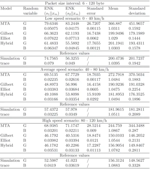
2.2 Markov chain based models performances results . . . 44
2.3 Performances results for packet size values belonging to 6-120 byte range . . . 48
2.4 Performances results for packet size values belonging to 120-216 byte range . . . 49
2.5 Computational complexity . . . 66
3.1 Simulation settings . . . 86
4.1 Simulation settings . . . 104
5.1 Traffic Table . . . 118
5.2 QOF and SOS characteristics . . . 132
Acronyms
AMC Adaptive Modulation and Coding AODV Ad-hoc On demand Distance Vector BE Best Effort
BER Bit Error Rate
BPSK Binary Phase Shift Keying BS Base Station
BWA Broadband Wireless Access CAC Call Admission Control
CDF Cumulative Distribution Function CID Connection IDentifier
CP Cyclic Prefix
CPS Common Part Sublayer CRC Cyclic Redundancy Check CS Convergence Sublayer
DCD Downlink Descriptor Channel
DIEM Delivering time Interference and ETT based Metric DIM Delivering time based Interference Metric
DMT Discrete Multi Tone
DSDV Destination-Sequenced Distance-Vector DSR Dynamic Source Routing
DTMC Discrete Time Markov Chain
EGPRS Enhanced General Packet Radio Service ETT Expected Transmission Time
ETX Expected Transmission Count FDD Frequncy Division Duplexing FFT Fast Fourier Transform FTP File Transfer Protocol
GCAD Greedy Choice with bandwidth Availability aware Defragmentation GPC Grant Per Connection
GPSS Grant Per Subscriber Station
IBI Inter Block Interference ICI Inter Carrier Interference
IFFT Inverse Fast Fourier Transform IP Internet Protocol
ISI Inter Symbol Interference ISP Internet Service Provider
IWPM Instant Weighed Probability Model
IWPM-2V Instant Weighed Probability Model - 2 Variables IWPM-3V Instant Weighed Probability Model - 3 Variables LAN Local Area Network
MAC Medium Access Control MCM Multi Carrier Modulation MIB management information base MPEG Moving Picture Experts Group MRR Minimum Reserved Rate
MSNEA Mini Slots Number Estimation Algorithm MSR Maximum Sustained Rate
MSS Mobile Subscriber Station NLOS Non Line Of Sight
nrtPS not real time Polling Service
OFDM Orthogonal Frequency Division Multiplexing OFDMA Orthogonal Frequency Division Multiple Access OSS Operation Support System
PADIEM Priority Aware Delivering time based Interference Metric PDF Probability Density Function
PDU Protocol Data Unit
PECF Packet Error Correlation Function PER Packet Error Rate
PHY Physical layer PMP Point to Multipoint PKM Privacy Key Management PSD Power Spectral Density
PSEA Packet Size Estimation Algorithm QAM Quadrature Amplitude Modulation QOF QoS Oriented Framework
QoS Quality of Service
QPSK Quadrature Phase Shift Keying RCT Radio Conformance Test
rtPS real time Polling Service RX Receiver
SAP Service Access Point SCN Service Class Name SDU Service Data Unit SFID Service Flow IDentifier SFM Simplified Fritchman Model
Acronyms xix
SNR Signal to Noise Ratio SOHO Small Office Home Office SOS Set of Old Solutions SS Subscriber Station SU Subscriber Unit
TDD Time Division Duplexing TP Test Purpose
TSS Test Set Structure TT Traffic Table TX Transmitter
UCD Uplink Channel Descriptor UGS Unsolicited Grant service UWB Ultra Wide Band
VoIP Voice over Internet Protocol WiFi Wireless Fidelity
WLAN Wireless Local Area Network
WMAN Wireless Metropolitan Area Network
WiMAX Worldwide Interoperability for Microwave Access XDSL X Digital Subscriber Line
1
The advent of a new technology: WiMAX
1.1 Introduction
The expected convergence of fixed and mobile internet services, the emergence of new applications and the growth of wireless subscribers will lead to an ever increasing demand for bandwidth in wireless access. The dream of 3G wireless systems is to provide high-speed multimedia services though mobile cellular technology, enabling subscribers to access the Internet and enjoy videophone, video on demand, games and multimedia chatting. However, the economic effi-ciency and data performance of 3G wireless systems have not been satisfactory mainly because it was not originally designed for data communications. Thus, burdened by license fees and deployment costs coupled with unsatisfactory performance, many 3G operators suffer from poor profitability. On the other hand, as the market for broadband and mobile communication services at-tains maturity in some countries, the communications industry has shown a limit in growth based on quantitative expansion. Meanwhile, wireless Internet access service is expected to be the new motivation for overcoming these limi-tations and increasing revenue. To make this service commercially successful, operators and Internet Service Provider (ISP)s have looked for new solutions for carrying Internet Protocol (IP) packets over the air more efficiently and economically. Nowadays, Wireless Local Area Network (WLAN) and Wire-less Metropolitan Area Network (WMAN), which conform to the IEEE802.11 and IEEE802.16 families, respectively, are attracting interest as solutions for wireless Internet access.
WLAN is a high-bandwidth, short-range, two-ways data communications system that uses radio waves rather than fiber or copper cable as its transmis-sion medium. WLAN is a flexible data communications system implemented as an extension to a wired network or as an alternative to a wired Local Area Network (LAN). Thus, wireless LAN combine data connectivity with user mobility. Today, most WLAN use the 2.4GHz frequency band, but the 5GHz band is rapidly emerging. WLAN may be installed to extend or replace a wired LAN in a corporate enterprise, a small or medium sized enterprise,
or a Small Office Home Office (SOHO) environment. A recent application of WLAN technology has been to offer public access to Internet-based services in small public deployment frequently referred to as hotspots.
Currently, the remarkable upsurge in demand for supporting both high-speed and high-quality applications in Broadband Wireless Access (BWA) networks has attracted the attention by both industry and academia. Among a variety of BWA technologies, IEEE 802.16 is a promising one to enable various services to solve the problem of providing enhanced services over the last mile. The IEEE 802.16 protocol, for wireless metropolitan area networks has been recently standardized to meet the needs of wireless broadband ac-cess. The 802.16 is also known as Worldwide Interoperability for Microwave Access (WiMAX), which is a no profit association with the scope to acceler-ate the WiMAX devices diffusion. Behind WiMAX logo there are important companies, for example: Airspan, Alvarion Aperto Networks, Ensemble Com-munications, Fujitsu, Intel, Nokia, OFDM Forum and Proxim Corporation are a set of these companies. WiMAX can serves Wireless Fidelity (WiFi) hotspots and can provide services to a wide coverage area with a radius of 50 kilometers. It is possible considering also Non Line Of Sight (NLOS) scenar-ios, in which a rate of 134 Mbps is reachable, this fact implies the possibility to provide broadband services at hundreds of users, using a single sector of a base station. Wireless technologies are becoming significantly: the IEEE 802.16 can increase system performance and decrease the cost of equipments. This technology can also provide the broadband connections ’on demand’ to all those places which need temporary connection (conferences, exhibitions, particular events and more).
WiMAX is faster than WiFi and the first technology is also characterized by a widest coverage area: in fact the WiFi coverage area can be measured in the order of square meters, instead for WiMAX we can tell about square kilometers.
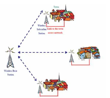
A typical scenario obtainable by WiMAX technology is depicted in figure 1.1:
• a Base Station (BS) is connected with a set of Subscriber Station (SS)s; • each SS can connect to internet a little group of buildings.
The IEEE 802.16 standard defines two protocol layers: Medium Access Control (MAC) layer and Physical layer (PHY); the MAC layer can support two different topologies:
• Point to Multipoint (PMP); • Mesh.
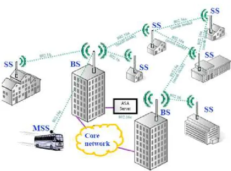
The first one allow to establish only links between BS and SSs (see figure 1.1). The BS in this way is the central point of the network. Instead in the second topology mode also direct links between SSs are allowed (see figure 1.2). WiMAX technology can be used for creating wide-area wireless backhaul network. When a backhaul-based WiMAX is deployed in mesh mode, it not
1.1 Introduction 3
Fig. 1.1. A typical WiMAX scenario in PMP mode
only increases the wireless coverage but also provides features such as lower backhaul deployment cost, rapid building, easy deployment, robustness and re-configurability. This will make it one of the indispensable technology in next generation networks.
The IEEE 802.16 protocol defines operations in both licensed and license-exempt bands. The licensed band deployment is useful for dense and competi-tive coverage areas, in this case in fact, the interference is the major challenge. The deployment in license-exempt bands is used to cover restricted area and also to limit the initial investments. A significant advantage of WiMAX tech-nology is the great flexibility in the network infrastructure deployment, this is due to the ability to define the width of the channel, the type of duplexing and the transmission techniques. This new technologies are a viable alternative to traditional broadband technologies such as X Digital Subscriber Line (XDSL), cable modems and fiber optics, as they allow to an ISP to create its own net-work infrastructure with a high scalability in terms of investment and services capacity. Summarizing, the WiMAX technology allow to ensure optimal per-formance:
• in terms of capacity, even with cell with very high load;
• in terms of coverage, although the presence of indoor Subscriber Unit (SU) reduces the performance.
Fig. 1.2. An example of WiMAX scenario operating in mesh mode
WiMAX technology is a very promising technology and it is characterized by a series of advantages. Certainly, it was conceived with the prospect of becoming the technology that could eliminate the digital divide problem, and is proposed, in its own right, to assume a leading role among the existing technologies.
Nevertheless, the solutions that are attracting increasing interest, are also the integrated architecture, in which two or more technologies can be inte-grated and can cooperate in order to guarantee high quality of services over large areas and to a large number of users. The chances to create integrated architectures are different; cooperation such as WiMAX WiFi, WiMAX -Ultra Wide Band (UWB), or WiMAX - 3G or other kind of cooperation can be considered. Surely a basic problem, which is common to all the inte-grated architecture, is to ensure quality of service to users. Each architecture, each protocol is characterized by its own mechanisms to ensure Quality of Service (QoS) in a network segment. But what happens when a data stream of a user must go through more than one segment of the integrated network? Once a protocol of a specific segment, admits a new call, and once the call has been moved to another segment, how can the QoS levels guaranteed at the instant of the admission call be maintained? The problem is to guarantee an end-to-end QoS.
The introduction of the promising technology IEEE 802.16 is related to the focus of this thesis. Our intent is to study the IEEE 802.16 protocol, considering both PHY and MAC layers, in order to elaborate a set of solutions
1.2 IEEE 802.16 standard evolution and related documents 5
useful to improve and enrich this protocol. The following of this chapter is conceived as an introduction to this technology and also as an introduction to the issues which have represented the our research challenge.
1.2 IEEE 802.16 standard evolution and related
documents
The IEEE 802.16 Working Group has defined the standard protocol which is behind the commercial name WiMAX. In particular the advent of the ac-tual state of protocol was developed by publication of a series of subsequent amendments. This process, at the actual state of the art, has produced four different network architectures as specified by IEEE 802.16 protocol, and other new kind of architectures are under study. In the following, in order to make the reader able to distinguish the various amendments and protocol versions, we introduce a brief description for each document related to IEEE 802.16 protocol:
• IEEE 802.16-2001, Air Interface for Fixed Broadband Wireless Access
Sys-tems.
This is the first standard proposed by 802.16 task group and it is approved on 6 December 2001 [1]. This standard specifies MAC and PHY features for a point-to-multipoint broadband wireless access systems providing multi-ple services. It is designed to support small office/home office applications and it is capable to guarantee a data rates of 134 Mbit/s. The protocol features are described by a layered structure organized in layers and sub-layers. The PHY is characterized by a set of air interfaces operating in frequencies range from 10 to 60 GHz, which is able to support data trans-mission in line-of-sight scenarios. MAC layer is instead organized by a set of sublayes in which very interesting is the presence of Privacy sublayer, it has the task to provides secure service supported by data encryption and privacy keys management.
• IEEE 802.16c-2002, Air Interface for Fixed Broadband Wireless Access
Systems - Amendment 1: detailed system profiles for 10-66 GHz.
The version c of IEEE 802.16 protocol [2] is approved on 11 December 2002 and it is an amendment updates and expands IEEE 802.16-2001 protocol. It presents sets of features and functions to be used in typical implemen-tation cases; also it represents an improvement to eliminate errors and inconsistencies. Obviously it is referred to 10-66 GHz licensed band. • IEEE 802.16a-2003, Air Interface for Fixed Broadband Wireless Access
Systems - amendment 2: medium access control modification and addi-tional physical layer specifications for 2-11 GHz.
The work group a of IEEE 802.16 protocol [3] started its work before group c but its results were approved only on 29 January 2003. This ver-sion is an amendment to 802.16-2001 protocol and adds to it a series of
important features. The first one is the mesh concept; in this way the ca-pability to consider a different topology is introduced. The addition of this characteristic causes many changes in the MAC and PHY functionality, in fact with the introduction of mesh concept was consequently introduced a complication in bandwidth and QoS management mechanisms. The other important improvement introduced by this amendment is related to PHY layer, in fact, the physical layer specification to operate in 2 to 11 GHz band, also in license-exempt bands, is specified. To operate in this band, new channel impairment phenomena, as multipath, has to be considered and to contrast it new air interfaces using Orthogonal Frequency Divi-sion Multiplexing (OFDM) and Orthogonal Frequency DiviDivi-sion Multiple Access (OFDMA) technique are introduced. With this two novelties the protocol is projected toward different scenarios.
• IEEE 802.16.2-2004, Coexistence of fixed broadband wireless access
sys-tems.
This document [4] is a recommended practice, approved on 9 February 2004 and defines recommendations for the design and coordinated deploy-ment of fixed broadband wireless access systems, with the focus to verify and control interference. In practice, the task of this work group is to define a document to promote coexistence for fixed broadband wireless systems and to specify how to manage coexistence in a shared environ-ment with acceptable mutual interference. This docuenviron-ment in particular address spectrum from 2 to 60 GHz.
• IEEE 802.16-2004, Air Interface for Fixed Broadband Wireless Access
Sys-tems.
This protocol citeref.5 is a revision of standard IEEE 802.16-2001 and it is approved on 24 June 2004. This standard can be considered as the final version for PMP and mesh network architectures. This documents is an improved version of protocol IEEE 802.16-2001 and contain also the revision and corrigenda introduced in the subsequent IEEE 802.16a-2003 and IEEE 802.16c-2002 versions. It summarizes all the MAC and PHY mechanisms in both PMP and mesh mode and also each air interface developed for line-of-sight and non-line-of-sight scenarios, considering also licensed and license-exempt bands.
• IEEE 802.16f-2005, Part 16: Air Interface for Fixed Broadband Wireless
Access Systems - Amendment 1: Management Information Base.
This standard [6] is approved on 22 September 2005 and amends IEEE 802.16-2004 standard. It specifies a management information base (MIB) for the MAC and PHY and associated management procedures. This docu-ment is produced taking into account the focus of defining the managedocu-ment object and the topics related to managed devices.
• IEEE 802.16e-2005, Part 16: Air Interface for Fixed and Mobile
Broad-band Wireless Access Systems - Amendment 2: Physical and Medium Ac-cess Control Layers for Combined Fixed and Mobile Operation in Licensed Bands and Corrigendum 1.
1.2 IEEE 802.16 standard evolution and related documents 7
This document [7], approved on 7 December 2005, updates the IEEE 802.16-2004 standard. The main feature which is introduced in this docu-ment is the user mobility. The task group e specifies a system for combined fixed and mobile BWA supporting subscriber stations moving at vehicular speeds in licensed bands under 6 GHz. It is based on OFDM transmission method with 256 Fast Fourier Transform (FFT) points, i.e. 256 subcarri-ers. It should operate in this bands supporting bit rates up to 15 Mbit/s to mobile SS and also higher layer handover between base stations or sectors are specified. This standard specifies also corrections to IEEE 802.16-2004. • IEEE 802.16k-2007, Media Access Control (MAC) Bridges, Amendment
2: Bridging of IEEE 802.16.
This version [8] is the shortest standardized document related to IEEE 802.16 protocol. It amends 802.1D protocol to support the bridging of the IEEE 802.16 medium access control. It is approved on 22 March 2007 and mainly specify a little set of additions and improvements for 802.1D. The IEEE 802.1D is the IEEE MAC bridge standard and allows communica-tions between two end stacommunica-tions belonging to separate LAN.
• IEEE 802.16g-2007, Part 16: Air Interface for Fixed Broadband Wireless
Access Systems - Amendment 3:Management Plane Procedures and Ser-vices.
This standard [9] amended the IEEE 802.16-2004 standard and it is elab-orated to specify each management aspect related to fixed and mobile broadband wireless systems. It specifies the management functions, inter-faces and protocol procedures. The main features are related to the en-hancements of the radio interface MAC Management messages, enhance-ments of the radio interface data plane capabilities and introduction of a set of primitives for the entities described in IEEE 802.16 protocol. It is approved on 27 September 2007.
• IEEE 802.16 Conformance protocols.
All the application cases, the base stations and the subscribers stations implementations, have to compliance with the protocol constraints and guidelines. The focus is to guarantee the interoperability between different system implementations. To verify the effective interoperability there is the need of a well defined Test Set Structure (TSS), Test Purpose (TP) and Radio Conformance Test (RCT). These tests are specified in a set of documents published in different times along the whole protocol process development. In the following the actual set of conformance protocols are listed:
– IEEE 802.16 Concormance01-2003, Part 1: Protocol Implementation Conformance Statement (PICS) proforma for 10-66 GHz WirelessMan-SC air interface [10], it is approved on 12 June 2003, it is a conformance
to IEEE 802.16-2001.
– IEEE 802.16 Conformance02-2003, Part 2: Test Suite Structure and Test Purpose for 10-66 GHz wirelessMan-SC air interface [11], it is
approved on 11 December 2003, it is a conformance to IEEE 802.16-2001 as amended by IEEE 802.16a-2003 and IEEE 802.16c-2002. – IEEE 802.16 Conformance03-2004, Part 3: Radio Conformance Tests
(RCT) for 10-66 GHz WirelessMAN-SC Air interface [12], it is
ap-proved on 12 May 2004, it is a conformance to IEEE 802.16-2001 as amended by IEEE 802.16a-2003 and IEEE 802.16c-2002.
– IEEE 802.16 Conformance04-2006, Part 4: Protocol Implementation Conformance Statement(PICS) proforma for frequencies below 11 GHz
[13], it is approved on 15 September 2006, it is a conformance to IEEE 802.16-2004.
For 802.16 protocol other work groups, not cited previously, have to be considered; these groups do not have yet terminated the standardization pro-cess and thus no standardized documents are produced. The future versions of IEEE 802.16 standard are the following:
• IEEE 802.16j, Amendment to IEEE 802.16e-2005 on Mobile Multihop
Re-lay.
Multihop relaying for coverage extension in wireless networks is an old concept, in a relay networks, several relay stations between transmitter and receiver work together to forward the signal transmitted from transmitter to receiver. The IEEE 802.16 working group has devoted a task group to incorporating relay capabilities in the foundation of mobile IEEE 802.16e-2005. Currently, this task group is in the process of finishing IEEE 802.16j, the Multihop Relay Specification for 802.16. This amendment will be fully compatible with 802.16e-2005 mobile and subscriber stations, but a BS specific to 802.16j will be required to operate for relays.
• IEEE 802.16h, Improved Coexistence Mechanisms for License-Exempt
Op-eration.
This task group is still far to realize the final document in which the focus is to develop the coexistence mechanisms in license-exempt bands. The coexistence word is related to the environment sharing between entities providing wireless broadband service using the same frequency spectrum. • IEEE 802.16m, Air Interface for Fixed Broadband Wireless Access Systems
- Advanced Air Interface.
The task group m is studying the development of an advanced air interface. This document will introduce a layered cell structure and also improvement in data rates achieving 100 Mbit/s for mobile users and 1 Gbit/s for fixed users.
1.3 An overview of MAC and PHY protocol layers
In the following subsections, we briefly describe the protocol stack as delin-eated by the IEEE 802.16 standard protocol. In the first subsection the salient
1.3 An overview of MAC and PHY protocol layers 9
points of MAC layer will be introduced and in the second subsection the PHY layer, with its five air interfaces, will be summarized.
Fig. 1.3. IEEE 802.16 protocol stack
1.3.1 MAC layer
IEEE 802.16 defines a single-level MAC with various modifications and im-provements published in various steps, which adds various physical layer specifics, covering both licensed and license-exempt bands. The IEEE 802.16 protocol was specified through a stack architecture, visible in figure 1.3.
The various sublayer can interact with each other and access to the services of the lower layers through the Service Access Point (SAP), so for example the Convergence Sublayer (CS) provides a set of services to higher layers through the CS-SAP, and in turn it enjoy the services of the Common Part Sublayer (CPS) through the services access point called MAC-SAP. The whole course in order to allow communications between equal entities, typical of a protocol defined by a stack architecture.
The protocol offers QoS mechanisms at both MAC and PHY protocol layer. In this section, we will see what is the MAC point of view and we are going to introduce what are the mechanisms offered by this layer in order to guarantee well defined levels of quality of service. In the first step we must distinguish between the different topologies supported by the IEEE 802.16 protocol. The protocol supports two different modes, the Point-to-Multipoint mode and the optional mesh mode. To correctly distinguish the two modes
we define what are the different entities that come into play in a WiMAX network:
• BS: Base Station; • SS: Subscriber station;
• MSS: Mobile Subscriber Station.
The SSs and the Mobile Subscriber Station (MSS) are the users stations, the last stations are equipped with mobility capabilities, while the BS is the base station and has a central role for different reasons in both operational modes.
In PMP mode case, the only connecting links existing between the various entities, are the links of BS with the various user stations, fixed or mobile. It is not possible any direct link between the various user stations, consequently all stations must be submitted by BS which act as a central entity for the bandwidth allocation and to registry the user stations. In the mesh mode case there are also the possibility to create links between the various SSs. In practice, a user station (SS), which does not fall within the range of a BS, can reach it by exploiting the presence of any link with the near user stations. In this way, the SS in order to communicate with the BS, can exploit a multi hop path built on a set of mesh links. A mesh link is a connection between two SSs. This is not applicable to MSSs stations that continue to be binding to the BS, although in a later versions of the protocol in mesh mode, under designing, the protocol designer want to introduce the possibility to use the mesh mode also with MSSs.
In mesh mode the BS loses the central role of the only entity capable of managing the bandwidth allocation but retains a certain importance because it is the only station to have access to the ”rest of the world”, making the role of gateway to Internet. The distinction between the two operational modes is necessary because in both cases the quality of service, is managed and assured in a different way and using different MAC mechanisms.
The MAC layer, as visible in figure 1.3, is divided into 3 different sublayers, the first of these, or the upper layer, is the Convergence Sublayer. The main task of the Convergence Sublayer is to ensure to different types of higher protocol layers, for example:
• packet protocols such as IP protocol; • ATM protocol;
the ability to communicate with the lower stack layers. The IEEE 802.16 protocol is a connection-oriented protocol, and between BS and SS can be created more than one connection (PMP mode). In this context, the conver-gence sublayer performs the delicate task of classification of SDUs, mapping the various SDUs from higher layers on the proper connection. In order to make effective this mapping, a set of classifiers is defined, and each SDU must be submitted to it, before being assigned to a connection. Among the vari-ous classifiers must be defined an application order, and if an SDU cannot
1.3 An overview of MAC and PHY protocol layers 11
be mapped on any connection, it will be discarded. Another special feature done by CS sublayer is the deletion of parts of the Protocol Data Unit (PDU) header that are repeated packet by packet, which can be rebuilt once reached the destination. Please note that this is possible because the MAC is linked to the connections, hence the packets sent over a connection have some repetitive fields, and this because they belong to the same data flow. The purpose of this, is to optimize the data transmission saving bandwidth.
The central sublevel is the Common Part Sublayer (CPS). It performs typical tasks of the medium access control layer, thus providing algorithms to ensure efficient coordination between the various entities that require band-width allocation.
The last sublevel that includes the MAC is the Privacy sublayer that give to service providers a strong protection from theft of service. Moreover, it protects the data flow from unauthorized access by strengthening the encryp-tion of the flows passing through the network. The Privacy sublayer provides a client / server management protocol authentication key where the BS (server), monitors the keys distribution to the clients. This sublayer is characterized by two main components:
• an encapsulation protocol for the encryption of data packets that are sent over the network: this protocol defines a set of encryption suites;
• a key management protocol: Privacy Key Management (PKM).
The MAC PDU is shown in figure 1.4, and consists of a fixed length header equal to 6 bytes, a payload that can contain one or more SDUs or SDU fragments or even can be absent, and finally optionally can appear the CRC field (Cyclic Redundancy Check). Please note that the Service Data Unit is the information coming from higher-layer protocol. In figure 1.4 is also visible the generic PDU header, which is different from header used to request bandwidth in PMP mode. The represented header is characterized by fixed length and contains several fields:
• HT: header type, which is used to distinguish between a generic header and bandwidth request header used in PMP mode;
• EC: Encryption Control, which is used to indicate if the payload is en-crypted;
• Type: it is used to indicate if the payload contains one or more subheaders; • Rsv: it is a reserved field, not used;
• CI: it indicates if the payload end with a CRC portion; • EKS: it is used to indicate the payload encryption key; • LEN: the length of the PDU, including header and CRC;
• CID: it is the connection identifier, it in mesh mode contains link and network identifier;
• HCS: header check sequence, it is used to detect header errors.
Inside the payload of a MAC PDU, can be carried both data and man-agement messages. The format of the manman-agement message is represented in
Fig. 1.4. MAC PDU
figure 1.5. The management message type contains the type of message con-veyed, and the ”management message payload” carries the actual message.
Fig. 1.5. Management message
In PMP mode each communication must be associated to a single service flow. The service flows are created after the SS has completed the registra-tion protocol with the BS. The registraregistra-tion is completed if the SS is able to maintain synchronization with the uplink and downlink channel, while re-ceiving DL-MAP, UL-MAP, Uplink Channel Descriptor (UCD) and Downlink Descriptor Channel (DCD) messages in regular way. The first two messages describe the allocations of bandwidth in downlink and uplink respectively, while the latter two messages describe the channel characteristics. The con-cepts of service flow and connection will be treated later in the subsequent section when the QoS mechanisms will be illustrated.
The PMP mode of 802.16 protocol is strongly oriented to the connection, each station is characterized by a 48 bits MAC address, and each connection is identified by a 16-bit Connection IDentifier (CID). Unlike the mesh mode, PMP mode has well distinguishable uplink and downlink. In downlink, the BS is the only station that is able to transmit, in broadcast way, without coor-dination with the other stations, and each user station, SS or MSS, retaining only what is directly to itself. The various SSs stations should instead share the uplink channel. The bandwidth request, by a general SS, may occur in several ways:
1.3 An overview of MAC and PHY protocol layers 13
• Bandwidth request header;
• Piggyback request (using the grant management subheader).
The bandwidth requests can be sent during the following transmission opportunities:
• Request IE;
• Any data grant burst type IE.
The BS can allocate bandwidth to SSs, periodically, in order to allow to the SSs the bandwidth requests sending. This mechanism is called polling and it can be of two types:
• broadcast polling;
• unicast polling (including the Poll Me bit: PM).
Obviously, in the case of broadcast polling, in the same transmission slot may be a contention; in which case the contention resolution method is the use of the exponential backoff. Once the various stations are sent the bandwidth requests to the BS, it can allocate the bandwidth in two ways:
• Grant Per-Connection (GPC), in which case the BS allocates bandwidth to the single connection;
• Grant Per-SS (GPSS): in this mode of bandwidth allocation, the BS in-cludes all the bandwidth requests, made by the same SS for all its connec-tions, and gives to the SS a single aggregate grant, thus the user station can divide to the various connections, the granted bandwidth.
In mesh mode, as previously anticipated, there is the ability to create and manage direct links between the SSs stations. In particular, in this mode, each entity is generically named ”node” and new concepts and terms absent in PMP mode are introduced. These new introduced terms are the following: neighbor, neighborhood and extended neighborhood of a node. A node is said to be neighbor of another node if there is a direct link between the two nodes, the neighborhood of a node is the set of all neighbor, or in another way is the set of nodes that are one hop away from the node, and the extended neighborhood, in addition to neighboring nodes, contains additionally all the neighbors of the neighborhood, or in other way, we can say that the extended neighborhood contains all the nodes that are two hop away from the node itself. As earlier mentioned, the BS loses the central role that characterizes the PMP mode, and in fact the basic principle that governs the mesh is the follows:
no one node can transmit on its own initiative, including the BS node, without coordinating its transmission within its extended neighborhood.
The BS does not have the central role of the only manager of bandwidth allocation, so all the network nodes have equal importance. In a network that operates in mesh mode, there are two different ways of allocating bandwidth
according to a kind of distributed or centralized scheduling. In the distributed scheduling, which in turn can be either coordinated or uncoordinated, all stations must coordinate their transmissions in their extended neighborhood. This type of scheduling uses all or a portion of the scheduling control subframe, to send its regular schedule and to propose changes of the same in a PMP mode, i.e. the messages used in this phase are sent in broadcast way.
Within a channel, all neighbors receive the same transmission schedule. All stations in a network, use the same channel to transmit the schedule in-formation. This information will be issued in the format requests - grants. The distributed coordinated scheduling ensures that all the transmissions will take place without having to rely on the base station. The uncoordinated scheduling, respecting the constraints of coordinated distributed scheduling, can ensure communications with fast setup on the basis of individual links. The uncoordinated scheduling is determined by requests and grants between two nodes, it must also take place in a manner that does not cause colli-sions with messages of coordinated scheduling and its traffic. Both modes of distributed scheduling, use a three - way - handshake protocol.
In summary, the differences between distributed coordinated and not co-ordinated scheduling, are the following:
• in coordinated scheduling the control messages are scheduled in scheduling control subframe in collisions free manner;
• in not coordinated scheduling, the messages must be sent in the data traffic portion frame, and may collide with each other message.
The second mode of bandwidth allocation is based on centralized schedul-ing. In this case, the BS determines the flow assignments on the basis of requests received by SSs. The BS works so as in PMP mode, the only differ-ence is that in this case not all the SSs can rely on a direct connection with the BS, hence the requests - grants message must be issued within the system in broadcast mode. The grants and the requests messages, in accordance with centralized scheduling, are broadcast only within their assigned transmission opportunities, in the scheduling control subframe. Obviously, the bandwidth allocation rules, described above, can be combined to achieve the goal of op-timizing the best allocation of bandwidth resources.
The scheduling mechanisms described above, use a series of messages that are exchanged within the node extended neighborhood. Here we see these messages in order to create a complete picture of the transmission mecha-nism described by the protocol. The messages that we look in detail are the messages: • MSH-NCFG; • MSH-NENT; • MSH-DSCH; • MSH-CSCH; • MSH-CSCF.
1.3 An overview of MAC and PHY protocol layers 15
The MSH-NCFG messages has a particular importance, because they have the task to carry the configuration information and the setting parameters of the network. This type of messages can be sent in control network subframe and therefore cannot be present in every frame, because this network alternate frames containing network control subframe and scheduling control subframe. When a new node is active and it want to start registration phase, it should listen to receive MSH-NCFG messages from neighbors. The receipt of this message is essential for a new node or a node that needs to repeat the syn-chronization phase. In fact in this message there are the descriptions of all the network parameters: the frame slots description, the neighbor nodes, etc.
The dispatch of such messages is made in a collision free mode and this is granted by the presence of two fields in MSH-NCFG message, these fields allow the calculation of the next transmission time of each neighboring node: • xmt holdoff exponent;
• next xmt mx.
Each node, at the instant which sends an MSH-NCFG message, will calcu-late its next transmission instant and expresses it in a range form by the two previous mentioned terms. In practice, the node does not say to the neighbors the next transmission instant, but sends an interval time in which the next transmission take place, this interval is defined by the following constraints:
nextxmttime > 2xmtholdof f exponent∗ nextxmtmx (1.1)
nextxmttime ≤ 2xmtholdof f exponent∗ (nextxmtmx + 1) (1.2)
Between a transmission and the next one, a node must waiting for in silence for an interval time equal to:
xmtholdof f time = 2xmtholdof f exponent+4 (1.3) When a node sends an MSH-NCFG message, in addition to sending infor-mation about himself, it will sends also inforinfor-mation about its neighborhood, so each node, collecting the information received from all the neighboring nodes will be able to reconstruct information about the 2 hop neighborhood (called also extended neighborhood). Within the extended neighborhood and in a certain slot, only one node can transmit.
The MSH-NENT message is used by a new node in order to carry out the requests for admission and registration in the network. When a new node is active and it wants to register itself at network, is to listen to MSH-NCFG messages, and after receiving two messages from a single source node, it can select a node to make the request for entry into the network. The selected node, to which the node make the request, is defined sponsor node and the new node is defined candidate node. The candidate node can use MSH-NENT messages to request the opening and subsequent closure of a channel through
which candidate acquire what is necessary to its configuration. Consequently, the MSH-NENT message may contain:
• net entry request; • ack net entry; • net entry close.
The MSH-NENT message as the previous MSH-NCFG, cannot be sent in any transmission opportunities, but only in a specific opportunity within a frame. This is the first opportunity that is present in the frame containing control network subframe, this opportunity is not present in every frame but appears regularly, with the same frequency, as the opportunities of the MSH-NCFG messages. The MSH-NENT message is subject to an algorithm, which decides whether a node can transmit or not, but unlike the previous message, will not necessarily happen in a collision-free manner, and if this happen, the node has to use an exponential backoff algorithm.
Other types of messages that hold great importance in the mesh mode are MSH-DSCH and MSH-CSCH messages. The MSH-DSCH messages are used in association with use of distributed scheduling, they can be sent at regular intervals to inform the neighboring nodes about the scheduling of the transmitting station. The transmission mode of the message is the same of MSH-NCFG message. In fact both types of message should be subject to the same algorithm that determines the instant of transmission of the various nodes. Also this message contains the same values, described for MSH-NCFG message, and used to determine the next transmission instant; a node must also coordinate the transmission in the extended neighborhood. Unlike the MSH-NCFG message, the MSH-DSCH message can be sent in one of the transmission opportunity present inside the scheduling control subframe. Such messages can be used for both the coordinated distributed and uncoordinated distributed scheduling, and that is for requests that are negotiated directly between two nodes. Now we describe the MSH-CSCH message. This type of message is used in case of centralized scheduling, it is sent in broadcast way from the BS to its neighbors, and the neighboring nodes will continue the processing to transmit bandwidth grants made by the BS.
In addition to transport bandwidth grants, these messages are used to transport the requests. In fact, each node can send an MSH-CSCH message containing its bandwidth request and the request of all the children nodes in its reachability subtree. Even MSH-CSCH, as well as the MSH-DSCH messages are sent in scheduling control subframe. In support of centralized scheduling mode, there is also the MSH-CSCF message, which allows the transmission of configuration messages for centralized scheduling mode. Indeed, this message contains information about the child nodes of the sender node, depending on the particular considered reachability tree. That message must be sent in the opportunities, dedicated to it, into the scheduling control subframe.
1.3 An overview of MAC and PHY protocol layers 17
1.3.2 PHY layer
The physical layer is the lowest layer found in the protocol stack. In particular, the protocol defines a single IEEE 802.16 MAC layer but different air inter-faces. Different air interfaces are defined to support the MAC level which take into account different characteristics because of the various frequency bands ranging they consider. Any system, that implements this layer, must respect the constraints set in terms of transmission techniques, supported modulation and many other specific characteristics.
The protocol provides for the possibility of using both single carrier mod-ulation techniques and multi-carrier modmod-ulation techniques such as OFDM technique (Orthogonal Frequency Division Multiplexing). The presence of so different air interfaces is due to the will of the protocol designers, in fact in this way they want to make the transmission robust and able to adapt to the type of scenario in which network devices are operating. Considering the single carrier modulation, it is perfect for an environment where there is not a high impact of multipath fading, and therefore we can consider an environ-ment characterized by a not frequency selective transmission channel, while the OFDM modulation, which is a very efficient multicarrier modulation, is right to the most difficult and frequency selective transmission channel. In the table 1.1 you can see the interfaces provided by protocol.
Table 1.1. Air interface nomenclature
Designation Applicability Duplexing
alternative WirelessMAN-SC 10-66GHz TDD FDD WirelessMAN-SCa below 11GHz TDD licensed bands FDD WirelessMAN-OFDM below 11GHz TDD licensed bands FDD WirelessMAN-OFDMA below 11GHz TDD licensed bands FDD WirelessHUMAN below 11GHz TDD
license exempt bands
The supported modulations are Binary Phase Shift Keying (BPSK), Quadrature Phase Shift Keying (QPSK) and from 16 to 256 Quadrature Am-plitude Modulation (QAM) with the possibility to obtain different data rates varying the encryption type. The 802.16 technologies support both Time Divi-sion Duplexing (TDD) and Frequncy DiviDivi-sion Duplexing (FDD) mode, allow-ing greater flexibility in deployallow-ing the network. In the TDD mode, downlink (related to communication from BS to SS) and uplink (related to communica-tion from the SS to the BS) operating in the same frequency band at different
times, alternate transmission of downlink and uplink frames. Since this alter-nation is very quick, you have the perception that the channel is active both in uplink and in downlink in the same instant. As stated above, the TDD is used for services that have an asymmetric traffic into the two different link, such as access to the Internet. In FDD mode downlink and uplinks signals are trans-mitted simultaneously on two different frequency channels, and this results in an inefficient usage of resources, where the traffic is asymmetric, because the downlink and uplink spectra are unused for a long time. Therefore, summing up, while the TDD is very helpful in the case of asymmetric traffic (i.e. Inter-net access), or in scenarios where there is not the pair of channels; the FDD, on the other hand, is more appropriate in the case of symmetric traffic (such as Voice over Internet Protocol (VoIP)). These suggest consideration as well as the physical layer is designed with attention to the quality of transmission, the wide range of choices, allows to developers the chance to play with all possible configurations in order to achieve high quality standards.
All the 802.16 technologies use AMC (Adaptive Modulation and Coding). This feature allows you to improve performance, and optimize the throughput and the range of coverage. The AMC, in fact, provides a dynamic range of modulation and code rate for each user, depending on the condition of the radio link. When the received signal is low, as in the case of terminal far from the BS, the system automatically selects a modulation more robust but less efficient in terms of capacity (such as QPSK), in order to keep the probability of error equal to the target level. When the signal level received is high, then high modulation (such as 64 QAM) are chosen without increasing the prob-ability of error. The capacity of WiMAX networks to use a robust scheme of adaptive modulation type, ensures broad benefits to large distances, with a high level of spectral efficiency and tolerance to the reflections of the signal. For example, if the base station is unable to establish a stable connection to a remote user using the modulation scheme of the highest level, 256 QAM, the modulation level is reduced to 16 QAM or QPSK with reduction of supply of throughput, but with increased efficiency on the distance. The so-called Adaptive Modulation and Coding (AMC) technique, have been proposed in order to be chosen the most effective scheme based on the state of the channel. The choice of levels of modulation encoding optimizes the required service. The 802.16 standard can achieves its high data rate and efficiency by using multiple orthogonal (overlapping) carrier signals instead of a single carrier ap-proach. This parallel carrier ability is called multi-carrier modulation (MCM) or discrete multi-tone (DMT), and is ideal for addressing errors that may arise in indoor and outdoor wireless environments.
1.3.3 QoS mechanisms
As we have previously introduced, the focus of this thesis, which will discussed again in detailed way in the following of this chapter, is to extol the protocol mechanisms to create a cross layer framework to provide services with well
1.3 An overview of MAC and PHY protocol layers 19
defined QoS levels. At this purpose, up to this point, we have introduced the basic concepts of the two layers and now we will illustrate the basic mecha-nisms supported by protocol to provide QoS.
The presence of these mechanisms gives the opportunity to provide ser-vices with high levels of quality, which is not achievable with other wireless standards. What makes IEEE 802.16 a strong protocol, in PMP operative mode, are few and well-defined concepts, such as the connection, the schedul-ing data service and the service flow. As mentioned above, the 802.16 protocol in PMP mode is strongly connection oriented, everything happens within it, and which is associated with the concept of service flow. Between BS and SS, everything happens within the connection. Let’s look in the following the various concepts just introduced.
The QoS parameters are linked to the service flow, but a service flow cannot exist if not associated with a connection. And the scheduling data service, which in a certain way classify the connections, are the completion of this complex structure. A single SS may provide services to an entire building, as a result, each SS can embrace within a single connection, all types of traffic of different users, with the same characteristics. So everything revolves on the concept of connection and service flow. The connections, identified by a CID, occur between CS levels, and it create a communication channel between convergence sublayer entities. The connections can operate in a dynamic way, they can be created, their parameters can be changed and finally, a connection can be deleted. In figure 1.6 the mechanism implemented at CS is shown, i.e. the mapping of the SDUs over the corresponding connections. Obviously, this game also contributes to the QoS classification , because in such a way, the SDU not delay tolerant will never be mapped on a connection that carries best effort traffic, and consequently, an SDU of delay tolerant application will not be mapped on a connection that can handle traffic with stringent delay constraints. All this in order to optimize the quality of services.
You may notice that the protocol 802.16 was born with QoS in the soul also in the quality of service offered to management message traffic. In fact, after that an a SS registers itself at the BS, between them will be instantiated three different management connections with different QoS levels:
• Basic management connection: used to exchange short urgent messages; • Primary management connection: carrying longer messages and delay
tol-erant;
• Secondary management connection: used to carry delay tolerant messages standards based.
Each connection is associated with a single scheduling data service and each data service is associated with a set of QoS parameters that quantify aspects of its behavior. Moreover, each scheduling data service is associated with specific bandwidth request mechanisms that allows it the respect of qual-itative constraints imposed by the particular application. The following are the four types of scheduling data service supported by 802.16:
• Unsolicited Grant Service (UGS): used with real time traffic that generates fixed-size packets on a periodic basis. Example of this kind of traffic is voice over IP. A connection, mapped on this type of scheduling, has an amount of bandwidth allocated by the BS, constant over time. An SS may use this connection to request bandwidth for other connections by setting Poll Me bit in one of the MAC PDU subheader. By setting this bit, SS require a polling by BS for connection of the same SS. In this way is obtained an optimization of bandwidth and this because there is not a bandwidth waste to send bandwidth request messages;
• Real-time Polling Service (rtPS): used for real time traffic that generates packets of variable size on a regular basis, an example is an Moving Picture Experts Group (MPEG) video. The mechanisms of bandwidth request associated to this scheduling data type are piggyback request and the unicast polling. The first of these mechanisms can include a bandwidth request for the connection within a PDU that carries data. This is also a mechanism that allows bandwidth saving. The unicast polling, instead, is realized by allocating, by the BS, a transmission opportunity to the SS. In this opportunity the SS can send the amount of bandwidth request that it need;
• Non-real-time Polling Service (nrtPS): suitable for not real time traffic with packets of varying size sent on a regular basis. An example could be the FTP traffic. The mechanisms of bandwidth request allowed in this case are the piggyback and unicast and broadcast polling.
• Best Effort (BE): The Best Effort scheduling data service is used for types of traffic that have no one stringent qualitative constraints of any kind. For example we can consider data traffic generated during an Internet session. In this case, all the bandwidth request mechanisms available by the Protocol, are allowed. Generally, a base station, once accommodate
1.3 An overview of MAC and PHY protocol layers 21
all the above types of traffic, assignes to best effort services the remaining bandwidth.
Analyzing the previous concepts, it seems clear the structure built by the protocol for the provision of quality of services. The priority offered, for example, to Voice over Internet Protocol (VoIP) or real time traffic, highlights a quality of service inherent in the nature of classes structure.
The framework will be completed and will appear in all its beauty when we go to describe the service flow concept. It represents the points of contact with the structure of the real and practical applications constraints. In fact, with the scheduling data service, we have not done anything other than a qualitative classification of traffic classes. Instead, the service flow, will make dirty its hands with the real constraints of user applications.
The QoS in IEEE 802.16 protocol is closely linked to the service flow con-cept: a service flow is a bi-directional flow of packets that provides a particular quality of service. Each service flow is characterized by specific qualitative con-straints (time, bandwidth, etc.). A service flow is enabled between an SS and a BS and to it are assigned the necessary characteristics for the particular type of transmission required by the SS; once activated one and only one con-nection will be associated with it. In this way, all communications will take place between SS and BS, with certain restrictions, can be sent in a single connection within a single service flow. They are created after the SS has completed the registration protocol with the BS. Service flow of various kinds can be created:
• provisioned, is the provided service flow that has not bandwidth reserved to it. These service flow is activated in deferred way;
• admitted: is a service flow that is not activated, but with reserved band-width;
• activated: is an active service flow.
When a service flow is admitted it is characterized by a given CID. Each service flow is mapped onto a connection, and each connection will belong to one of scheduling data service offered by the protocol in basis of required QoS. Only an activated service flow may forward packets. For each service flow, and thus connection CID, will be associated a set of parameters, the main parameters defining the qos for the particular services are:
• MSR: Maximum Sustained Rate; • MRR: Minimum Reserved Rate; • maximum-latency;
• maximum jitter; • priority.
In downlink, once the MSR parameter is defined, the BS does not need any more. For a given connection, there is a mapping with an active service flow and the minimum data rate is guaranteed by MRR parameter. Each