POLITECNICO DI MILANO
Scuola di Ingegneria Industriale e dell’Informazione
Corso di Laurea Magistrale in Ingegneria Meccanica
A new lightweight design for Power Tongue PCT 130
Supervisor:
Prof. Giorgio COLOMBO
Company supervisor:
Ing. Lorenzo ZILIANI
Candidate:
Edoardo BRUZZI Matr. 854925
Academic Year
2017/2018
3
Table of content
Abstract ... 9
Chapter 1: Introduction ... 11
1.1 Company Presentation... 14
1.2 Objectives and structure of the thesis ... 15
Chapter 2: The PCT 130 Power Tongue - Current solution ... 17
2.1 Positioning group ... 18
2.2 Sequences group ... 22
2.3 Operational sequences ... 24
2.4 Identified problems ... 25
2.5 Design parameters ... 26
Chapter 3: Improvement on suspension group ... 29
3.1 Suspensin group components ... 30
3.2 Hydraulic actuator dimensioning ... 30
3.3 Power Tong’s tubular support development ... 40
3.4 Power Tong’s tubular support dimensioning ... 42
3.5 Bearings assessment ... 50
3.6 Suspension system’s 3D models ... 52
Chapter 4: Improvement on handling group ... 57
4.1 Horizontal displacement group components ... 58
4.2 Bearings choice and assessment ... 58
4.3 Guides dimensioning ... 66
4.4 Telescopic guide 3D models ... 75
4.5 Telescopic cylinder design ... 77
4.6 Telescopic hydraulic cylinder 3D models ... 86
Chapter 5: Improvement on PCT assembly ... 89
5.1 Reduction gear ... 92
5.2 New rotation group configuration ... 98
5.3 PCT dimensions analysis ... 99
5.4 PCT positioning on the drill floor ... 103
Chapter 6: Conclusion ... 107
5
List of figures
Figure 1.1 drillmec PCT 130 ... 11
Figure 1.2 Blohm and Voss Power tong ... 12
Figure 1.3 Bentec iron roughneck ... 12
Figure 1.4 MH RNX ... 13
Figure 1.5 parking position ... 14
Figure 2.1 actuator for vertical displacement ... 18
Figure 2.2 rotating base ... 19
Figure 2.3 Pitching actuators ... 19
Figure 2.4 arm's actuators ... 20
Figure 2.5 parking position ... 21
Figure 2.6 working position ... 21
Figure 2.7 Spinner group ... 22
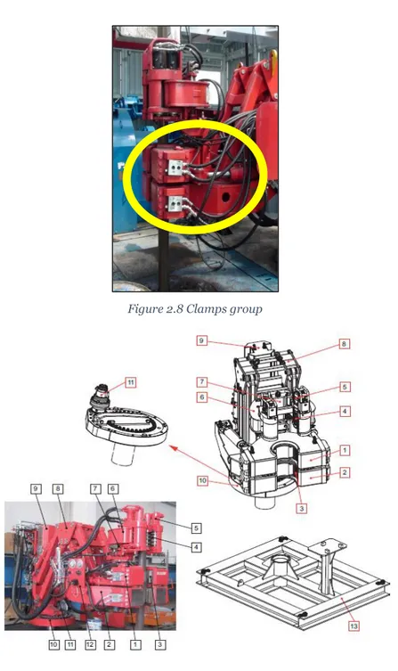
Figure 2.8 Clamps group ... 23
Figure 2.9 PCT elements ... 24
Figure 3.1 weights and moments evaluation ... 31
Figure 3.2 Arm and spinner's group equipement weights and distances ... 32
Figure 3.3 Spinners and clamps' weights and distances ... 32
Figure 3.4 fixation types and how to evaluate L1 L2 and L ... 39
Figure 3.5 cross section of former supporting container ... 41
Figure 3.6 guide for dimensioning of standard plain bearings ... 51
Figure 3.7 Vertical section of suspension group in closed and opened configuration ... 53
Figure 3.8 Suspension group in closed and opened configuration ... 54
Figure 4.1 Bearing's components ... 60
Figure 4.2 bearing section and dimensions ... 61
Figure 4.3 Guide model ... 64
Figure 4.4 Guide profile ... 67
Figure 4.5 Inclined flanges ... 69
Figure 4.6 Parallel flanges ... 69
Figure 4.7 fully open guide ... 76
6
Figure 4.9 telescopic cylinder ... 78
Figure 4.10 telescopic cylinder fully open ... 86
Figure 4.11 telescopic cylinder at zero stroke ... 87
Figure 5.1 former column and rotation group ... 89
Figure 5.2 Former rotation group... 91
Figure 5.3 pinion-fifth wheel coupling ... 92
Figure 5.4 circle inscribing the PCT ... 94
Figure 5.5 service factor values ... 96
Figure 5.6 reduction gear's characteristics ... 97
Figure 5.7 comparison of dimensions former-actual reduction gear ... 98
Figure 5.8 main dimensions of the PCT-side view ... 100
Figure 5.9 PCT's width-front view ... 101
Figure 5.10 former PCT dimensions-side view ... 102
Figure 5.11 PCT in parking position on the drill floor ... 103
7
List of tables
Table 3.1 Lifting actuator's input data ... 33
Table 3.2 Cylinder dimensions and stress assessment ... 37
Table 3.3 buckling assessment... 40
Table 3.4 PCT Deflection assessment ... 44
Table 3.5 Inner tube bending assessment ... 47
Table 3.6 Outer tube bending assessment ... 47
Table 3.7 Inner tube shear stress assessment ... 48
Table 3.8 Outer tube shear stress assessment ... 49
Table 3.9 Bearing assessment ... 52
Table 4.1 bearing dimensions ... 61
Table 4.2 bearing's assessment ... 65
Table 4.3 guide dimensions and assessment ... 67
Table 4.4 flange assessment parameters ... 73
Table 4.5 guide bending assessment ... 75
Table 4.6 Input data for telescopic cylinder ... 78
Table 4.7 dimensioning of first and second stage ... 81
Table 4.8 Third stage dimensionig ... 82
Table 4.9 Stress assessment... 83
Table 4.10 buckling assessment... 86
9
Abstract
The theme of this thesis is the analysis of the issues concerning a key component of the drilling rigs, the Iron Roughneck or Power Compact Tong, with the final aim at finding inventive solutions that can overcome them.
The study begun with a deep analysis of all the elements composing a Power Tong and the problems they led throughout the lifecycle of the component, both from a structural and functional point of view. The study is thereafter focused on the development of a new suspension system, that accomplishes the tasks of lifting the Power Tong and keeping it anchored to the drill floor, with the aim of keeping the same performances of the previous system and reducing its dimensions and weight.
Subsequently, the attention has shifted upon the handling group, whose job is to bring the Power Tong close to the centre well and couple it to the suspension and rotation group. Throughout the study of innovation, it has been possible to develop a new system with reduced dimensions and weights with respect to the previous one, without affecting its performances.
Finally, after the realization of the 3D models of the new groups, it has been studied how to mount them together with the other groups of the Power Tong in the better way, requiring to slightly modify also the configuration of the rotation group.
The final analysis of the so obtained new Power Tong has shown that, in addition to the solution of the operational and structural problems of the former groups, it has been possible to reduce its total dimensions and weight, leading to desired economic benefit for the company
11
Chapter 1: Introduction
This thesis concerns the Power Compact Tong, one of the most important components of a drilling rig. The Power Tong is basically a screwdriver controlled by the operator from his console that has the task of screwing two drill pipes together and subsequently tight them throughout the drilling phases and is also employed to decouple two drill pipes whenever it is necessary. The importance of this component is due to the fact that, before it was born, the drill pipes were connected by the operators with dedicated tools, that involved high risks for their safety. With the development of the Power Tong, that is completely automated, it has been possible to significantly increase the safety of the operators and, at the same time, make the operations faster.
There are several different Power Tongs on the market, each one with its own name and configuration, throughout this thesis, the adopted terms are the ones used at the company. In Figure 1.1 is reported the drillmec’s Power Tong, called PCT 130
12
The development of this thesis started from an analysis of the main alternatives offered by the competitors, the most popular is the FloorHand FH-100, produced by Blohm and Voss
Figure 1.2 Blohm and Voss Power tong
This power tong produced by Blohm and Voss is quite similar to the drillmec’s one, it ensures the same break out torque, equal to 130kNm, ad it provides it in the same way the PCT 130 does. The main difference regards the handling system, that in the PCT 130 is formed by a robotic arm, while in the FH-100 is made up of a framework that holds it up. Another alternative is furnished by Bentec with the Iron Roughneck IR 100-5-B.
13
The Bentec Iron Roughneck is quite similar to the Blohm and Voss one, presents the same screwing and tightening system of the PCT 130 and has a framework that holds it up like the one of the FH-100 that allows to displace it on the centre well.
MHWirth’s MH RNX is another kind of Power Tongue, that allows to furnish a higher break out torque, equal to 150 kNm by menas of a system very close to the one of the other Power Tongues but with grater dimensions. Moreover, it differs for the handling group, that is made up of a pantograph arm.
Figure 1.4 MH RNX
The ST-120 Iron Roughneck is the Power Tongue produced by National Oilwel Varco, one of the main competitors of Drillmec. It is presents groups similar to the PCT 130 and MH RNX, presenting the same concept for the spinners and clamps, and slightly differing only for the handling group, that presents an extendable arm too.
14
Figure 1.5 ST 120
1.1 Company Presentation
Drillmec S.p.A. is an international leader in design, manufacturing and distribution of drilling and workover rigs for onshore and offshore applications as well as a wide range of drilling equipment belonging to the Trevi group, a worldwide leader in the field of soil engineering, together with Soilmec, Petreven and Trevi. Trevi Group is a multinational organization with more than fifty years of activity that counts on more than 6000 employees in 70 countries in a structure composed of five Group companies and 30 subsidiaries.
Drillmec, born by absorbing three companies in the territory of the province of Piacenza: Ballerini, Massarenti and Branham, active in the drilling field. The company realizes the majority of the elements composing a rig, that is set up and tested at the holding that subsequently certifies it according to the European legislation. Drillmec realizes every kind of rig: hydraulic, mobile and conventional
15
both onshore and offshore. The company’s customers are drilling contractors from all over the world e.g. Petreven, Pergemine, Saipem, Enafor; that furnish Drillmec’s rigs to the main oil and gas companies such as Eni, Esso, Shell, Gazprom. In order to manage the rigs deployed all around the world, Drillmec controls branches in the United States of America, India and Belarus, although the headquarter is in Piacenza. The company focuses its attention in the realization of the majority of the elements composing a rig, going in the specifics of the design and realization phases of the single component.
1.2 Objectives and structure of the thesis
The objective of this thesis focuses upon the necessity to solve the structural issues of the Power Tong to create a component that can be competitive on the market. To do so, it has been necessary to study and develop brand new elements to substitute the former groups that could be modified, that are the suspension, rotation and handling groups. One of the target to increase its competitiveness is to reduce its total dimensions but, at the same time, the performances of the Power Tong must not be affected by the implementation of new groups. So is important that the new groups can lift, handle and rotate the same weight the former groups could move, and the range of movements must not be decreased. The performances are better detailed in the following chapters.
The thesis is structured in this way: in the second chapter is explained and analysed the current solution, with a description of the problems concerning the groups. The next chapter describes how the suspension group has been improved and reports the 3D models of the new group. Chapter 4 describes the inventive solutions concerning the handling group that has been developed and then modelled. Finally, in chapter 5 all the changes required by the rotation group in order to allow the
16
mounting of the two new groups are reported and chapters 6 sums up the obtained conclusions at the end of the project.
17
Chapter 2: The PCT 130 Power Tongue -
Current solution
The Power Tong is a key component on a drilling rig because allows to accomplish the phases of Make Up, consisting in the spinning and tightening of the drill pipes, and the Break out phase, consisting in the decoupling of two drilling pipes.
The elements with which the power tong can be used are the drill pipes and the drill collars; this last are the elements with the bigger diameter that the power tong must be able to be employed with.
Being reeved up the drilling floor, where there are limited spaces due to the presence of the windlass, mouse hole, tubes for recirculation of muds and so on, and for the security of the workmen operating on the floor, the PCT requires to be as much compact as possible. This necessity led to the development of two distinct groups:
Positioning Group: encases all the elements that guarantee to the PCT
the degrees of freedom to allow the positioning on the drill floor
Sequences Group: includes all the components to allow the PCT to
accomplish all the tasks it is design for
Po
w
er
t
ong
ue
-PC
T 13
0
Positioning group Suspension group Rotation group Pitching group Handling group Sequences group Spinners group Clamps group18
2.1 Positioning group
The positioning group includes the suspension group, the rotation group, the pitching group and the handling group. It has four degrees of freedom: pitch, rotation around the vertical axis, vertical displacement and horizontal displacement. Each group is responsible for acting on a specific degree of freedom as explained below.
Suspension group: the suspension group allows the vertical
displacement, obtained thanks to a hydraulic actuator located on the back of the PCT’s column. For what concerns the positioning control, is not present any system, since is managed by the operator that has a clear view on the drill floor, being able to regulate the clamps on the tool joints.
Figure 2.1 actuator for vertical displacement
Rotation group: The PCT has the ability to rotate around the
column’s base, in this way the operator can orientate it towards the centre well. The rotation is obtained by means of a hydraulic motor
19
and, for safety reasons, the self-centring is not enabled since the PCT could hurt the operators close to it.
Figure 2.2 rotating base
Pitching group: two pistons located under the lower clamp allow to
adjust the PCT’s inclination. Some overcentre valves inhibit the undesired movement of those actuators.
20
Horizontal displacement-handling group: Allows the PCT to
reach the centre well when in parking configuration and vice versa, opening and closing the handling arm. This movement is obtained thanks to two couples oh hydraulic actuators. The couples are one for each of the two upper beams closer to the column, and are made of two cylinders with different length. The longer cylinder allows to completely open the arm while the other, the Well centre setting cylinder, allows to reach the centre well, helping the operator to calibrate the distance.
21
Figure 2.5 parking position
22
2.2 Sequences group
The group incorporates all the elements that enable the PCT to meet its screwdriver tasks, coupling or decoupling the drill pipes depending on the work situation, in quick and safe way for the workmen.
Spinners group: allows to quickly screw the male thread of the pipe
to add to the string without providing the tightening torque, or to unscrew two pipes once the tightening torque has been removed. Four rollers are equipped, each one with his own hydraulic motor, and a hydraulic actuator allows the clamping of the rollers around the pipe body.
Figure 2.7 Spinner group
Clamps group: Made up of two different clamps, the lower clamp
holds still the pipe in the centre well while the upper clamp gives the tightening torque. The two clamps must be parallel to enable the displacement from or to the centre well. The clamp is rotated thanks to two hydraulic pistons, one on each side, next to which is present an
23
electric sensor that informs the operator about the inclination of the clamps. The clamps are closed by means of two hydraulic actuators per clamp.
24
Figure 2.9 PCT elements
2.3 Operational sequences
Make up
When the operator gives the command to start the Make Up sequence, the four rollers of the spinner close around the drill pipe’s body with a pre-set force. Then the spinners start rotating, following the drill pipe through the descent thanks to a double spring. Once the screw has finished, the rollers are opened and the lower clamp closes around the drill pipe. The upper clamp rotates of 20 degrees in counter clockwise direction, clamping on the drill pipe and rotating of 40 degrees in clockwise direction. If with one rotation the tightening torque is not reached, this sequences are repeated up to three times. Whereupon if the torque is not sufficient in necessary a restarting of the operations. In this phase is possible to regulate both the maximum torsion and the maximum clamping strength. In this way the torque given is guaranteed even if the clamps surfaces are worn providing less friction.
Break out
The two clamps clamp on the tool joints of the drill pipes; the upper clamp rotates counter clockwise exerting the maximum break out
25
torque and, when the pipes are no more tightened, the clamps open back. Afterwards, the spinners encase the drill pipes, screw them off and open back. Once the break out sequence is over, the upper clamp comes back parallel to the lower clamp to repeat the break out sequences.
2.4 Identified problems
The aim of this project is to solve the problems that afflict the PCT 130 guaranteeing at the same time the performances it provides, to obtain a product that can be competitive in the market avoiding structural and operational difficulties that decrease its value.
An analysis carried out with the operator and with the developer of the company has allowed to draw up a list of the issues arisen and all the technical specifications it has to guarantee, that are the starting point of the development of the project.
The issues concerning the PCT that the project aims to solve are:
Weight and dimensions to be reduced, to decrease the production costs, decrease the assembly and disassembly times and facilitate the operative positioning
Breaking of the supporting rod of the spinners due to absence of an auto levelling system
Necessity of manual levelling of the key, requiring time loss and leading to frequent incorrect levelling
These issues are mainly connected to the suspension and handling systems, that require to be redesigned with innovative concepts that can improve the design of the PCT solving the problems and furnishing a profit for the company at the same time.
26
2.5 Design parameters
The systems composing the PCT that are object of the study are the suspension group and the handling group, that has been completely redesigned, and the rotation group, which has been subject just to small changes to ensure the mounting of all the new components. The design parameters of the suspension group are:
The lifting force, that must be capable of rising the PCT, considering all the components it is made of
The maximum reachable height, equal to the one of the previous system that must be guaranteed without increasing the dimensions of the group
For what concerns the handling system, the design parameters to be satisfied are:
The displacement force, that must be able to horizontally displace the clamps and spinner groups
The length of the guide, that must guarantee to reach the centre well, where all the operations the PCT performs are accomplished
The dimensions when in parking position, that must not exceed the ones of the previous system
Implementation of an auto-levelling system or the development of a handling system that does not require it
Regarding the rotation group, the parameter to be satisfied is just the rotation torque, that must guarantee the possibility of rotating the whole structure when it is in parking position.
29
Chapter 3: Improvement on suspension
group
The first group whose configuration has been studied is the suspension group. The aim of the study of innovation is to develop a new lifting solution reducing the encumbrances, guaranteeing the performances provided by the previous technology. The first idea consisted of a telescopic cylinder, appointed to substitute the former actuator for lifting, and a telescopic column, intended to ensure the same lifting height of the previous column whilst it becomes more compact when the PCT is in the parking configuration.
In this way, when the PCT is parked, the length of the lifting group is reduced up to one third of its total length and to reduce even more the encumbrances the drill floor layout has been analysed to find out if it was possible to optimize the empty spaces of the structure. After a research concerning the different layouts of the previous rigs and the customers’ requests for the positioning of the components, it was found out that the empty space beneath the drill floor in the usual PCT’s positioning area is extended enough to allow the anchorage of the lifting group to the substructure of the probe plane. In this way, when the lifting group is all closed, it is also “hidden” below the drill floor level, reducing even more the encumbrances in the working area. The development of the project started from a preliminary analysis of the suspension group design: it is required a trade-off between the necessity of having a short lifting group when closed and a not too much wide group. This is important since, as we increase the number of the stages, the width of the actuator and of the supporting system increases too.
The exploratory design esteemed a three-stages actuator, but after an investigation of the elements of the probe plane ‘s substructure it was decided to slightly rearrange some elements in order to obtain enough
30
space to realize a single stage actuator, assuring a simpler configuration to develop, exploiting the rig’s layout.
3.1 Suspension group components
The group is composed by the hydraulic actuator, the lifting column and the bushes that allow the sliding of the moving part of the column along the fixed part. This last is made up of two concentric tubes, the inner one accomplishes the function of fixing the suspension system to the substructure of the rig, while the outer tube is the sliding part that has also the task of supporting the whole PCT by means of a flange upon which the rotation group is mounted.
This is a whole new system, that has never been studied in the company so a deep analysis of the components is required.
3.2 Hydraulic actuator dimensioning
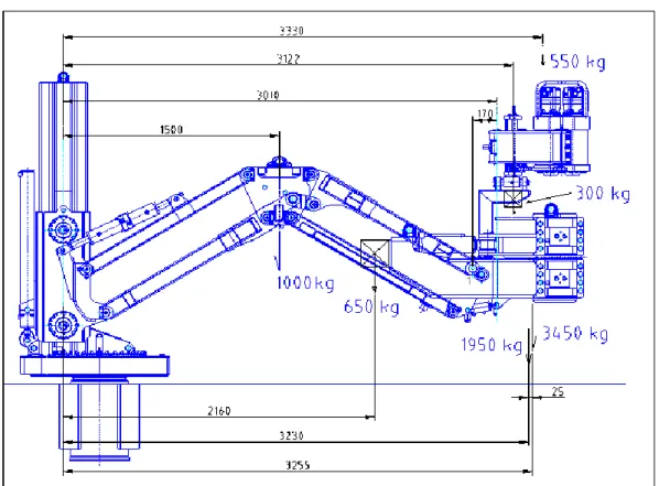
The first step of the design of the new suspension group was the dimensioning of the actuator. The hydraulic cylinder must be able to lift PCT so the dimensioning started from the evaluation of the weights of the system, taken from the 3D models developed on the software CREO Parametric.
Starting from the old PCT, the weights of all the groups were extracted, considering the spinners, the clamps and the arm. In this way we can know the minimum lifting force the actuator must guarantee. For the arm, the old system has been considered since we know that the new configuration will have at most the same weight.
Throughout this operation it has been possible to estimate also the distances of the centres of mass of all the groups from the column. In
31
this way also the moments acting on the column can be estimated. Those moments will be useful when the assessment of the structure will be performed.
The evaluation of the weights through Creo Parametric is not enough, because there is also the equipment to be considered. To avoid an underestimation of the weights, they have been increased of a factor equal to 1.2
32
Figure 3.2 Arm and spinner's group equipement weights and distances
33
The input data for the design of the actuator, collected in Table 3.1, are the working pressure and the material’s characteristics, in addition to the PCT’s weight and the required height the cylinder must guarantee, equal to 1 metre.
Table 3.1 Lifting actuator's input data
The working pressure is equal to the one of the previous lifting system, since is imposed by the hydraulic system of the rig, while for the material has been chosen a steel that ensures good performances in this field.
Once the input data where determined, the design of the actuator started from the minimum dimensions it needs to fulfil its task. The minimum required diameter is obtained starting from the resistance force the cylinder has to overcome, that is the PCT’s weight. Knowing also the working pressure the minimum required diameter is:
𝑑
𝑚𝑖𝑛= 2√
𝑊
𝜋 ∙ 𝑝
Where W is the weight of the PCT multiplied by a factor equal to 2, expressed in Newton [N], p is the working pressure [Mpa].
The minimum cylinder body diameter, instead, must not reach the σlim
and is obtained with the formula:
𝐷𝑚𝑖𝑛 = 𝑑𝑚𝑖𝑛 ∙ √
1
1 −
𝜎𝑙𝑖𝑚
2𝑝
PCT130 weight W 4480 kg 43948,8 N 43,9488 kN
Workig pressure p 120 bar 12 Mpa 12 N/mm2
cylinder body's material 39 NiCrMo3
Yielding strength σy 785 N/mm2 Young's modulus E 210000 N/mm2 Breaking load σuts 980 N/mm2 Allowable sigma (Yielding stregth/1,7) σlim 461,7647059 N/mm2
34
The σlim is equal to the Yielding strength of the material divided by a
factor equal to 1,7.
Once the minimum diameters where determined the whole cylinder’s dimensions have been fixed: to ensure safe working conditions of the cylinder the piston and cylinder body diameters have been increased to 130 mm and 150 mm respectively. The thickness of the cylinder results equal to 10 mm and the piston rod diameter (dr) has been chosen equal
to 60 mm. This last quantity is obtained by means of a trade off since influences two cylinder’s characteristics: the lifting force of the cylinder and the buckling load. This is because decreasing the piston rod’s diameter the lifting force increases, while the rigidity of the rod decreases, leading to a worsening of the buckling assessment, that will be lately checked.
The thickness of the cylinder has been found out following the recognized standard of hydraulic cylinders. The DNVGL-CG-0194 furnishes the method to evaluate the minimum required thickness, the wall thickness of the cylinder body with pressure in d shall be dimensioned according to the following:
𝑡 =
𝑝 ∙ 𝑅
𝜎
𝑡∙ 10 ∙ 𝑒 − 0.5 ∙ 𝑝
+ 𝑐
where:
t = required wall thickness, mm p = design pressure, bar
R = internal cylinder tube radius, mm σt = allowable stress, design stress, N/mm2 e = welding factor = 1 for seamless pipes c = corrosion allowance, usually 0.3 mm
35
The lifting force assessment has been performed calculating the resultant force acting on piston due to the pressure of oil pushing the piston’s surface with the formula:
𝐹 = 𝑝𝜋
𝑑
2
− 𝑑𝑟
24
The force exerted by the piston results equal to 1,4 times the weight used as reference for the assessment. The weight that the piston must be able to lift is equal to twice the actual PCT’s weight. The weight to be lifted has been increased in order to be sure that the cylinder works in fully safe conditions.
Subsequently, knowing all the dimensions of the cylinder’s components, the inertia of the piston rod and of the cylinder body have been calculated with the formula:
𝐽 =
𝜋
64
(𝐷𝑜
4− 𝐷𝑖
4)
Where Do is the outer diameter and Di the inner diameter for a generic circular hollow section. In our case, only the cylinder body has a hollow section, while the piston rod has a solid cross-section.
The performances of the hydraulic cylinder have been verified, afterwards an analysis of the state of stress of the actuator is mandatory. The cylinder is a pressure vessel, subject to a pressure equal to 120 bar. The thickness of the cylinder does notallow to use the Mariotte formulae because the diameter is less than 20 times the thickness, so the hypothesis of membranous behaviour must be rejected. Therefore, the main stresses where calculated considering the formula for the thick cylinder model, in order to evaluate the equivalent stress.
36
For the sake of completeness where computed and compared both Von Mises (σvm) and Tresca equivalent sigma (σtresca) with the formulae:
𝜎𝑡𝑟𝑒𝑠𝑐𝑎 =
2𝑝𝐷
2(𝐷
2− 𝑑
2)
𝜎𝑣𝑚 = 𝑝√
3(𝐷
4+ 𝑑
4)
𝐷
2− 𝑑
2Once the equivalent sigma where obtained it was possible to compute the safety factor, that expresses if the actuator has been designed in safe enough conditions.
The safety factors were computed comparing the equivalent sigma to the maximum allowable stress that is, as stated before, dividing the Yielding stress of the material by 1,7. The resulting safety factors, comparing both the Von Mises and Tresca equivalent sigma where respectively equal to 5,07 and 4,79, showing that the cylinder had been correctly dimensioned.
All the data and calculations are summarized in table 3.2, where the cells corresponding to the safety factors are green since the computed values are big enough to ensure the correct behaviour of the cylinder.
Minimum diameter required - lifting twice
the weight dmin 97 mm
Minimum cylinder body diameter -
due to allowable σ Dmin 100 mm
Piston diameter d 130 mm
Thickness t 10 mm
37
Average cylinder diameter Dm 140 mm Piston rod diameter dr 60 mm Piston rod inner diameter (if hollow) di 0 mm Average diameter-thickness rate Dm/t 14 Cylinder body inertia J2 J2 10830640,7 mm4 Piston rod inertia J1 J1 636172,51 mm4 Average cylinder head sealing
diameter 140,00 mm
lifting force assessment 125,29 kN SF - considering twice the PCT weight 1,43 allowable sigma σlim 461,76 N/mm2 TRESCA: equivalent sigma σt 96,43 N/mm2
SF σlim/σt 4,79
Von Mises: equivalent sigma σVM 91,02 N/mm2
SF σlim/σVM 5,07
Table 3.2 Cylinder dimensions and stress assessment
The final appraisal to perform to complete the cylinder design is the buckling assessment. It has been performed following the DNVGL-CG-0194 regulations.
The regulations describe how to perform the assessment, the DNV GL guidelines contain methods, technical requirements, principles and acceptance criteria related to classed objects as referred to from the rules.
This standard gives the requirements for which the Society bases the approval of hydraulic cylinders, including requirements for documentation, design, manufacturing and testing.
This standard is applicable for hydraulic cylinders when referred to in the Society's rules or other relevant Society's standards.
The DNV GL provides the formulae and the acceptance criteria for the required buckling calculation for cylinders used for pushing.
𝐼
1=
𝜋(𝐷
𝑜4
− 𝐷
𝑖4)
38
𝐼
2=
𝜋(𝑑
𝑜 4−𝑑
𝑖 4)
64
where:— I1= moment of inertia for the cylinder body, mm4 — I2= moment of inertia for the piston rod, mm4 — Do= outer diameter of the cylinder body, mm — Di= inner diameter of the cylinder body, mm — do= outer diameter of the piston rod, mm — di= inner diameter of the piston rod, mm
Is thus possible to compute the factor Z as follows:
𝑍 =
𝐿
1𝐼
1+
𝐿
2𝐼
2+ (
1
𝐼
2−
1
𝐼
1) ×
𝐿
2𝜋
sin(2𝜋
𝐿
1𝐿
)
Where:— L1= visible length of the piston rod in fully extracted position from centre of its mounting, mm
— L2= length of the cylinder part from the centre of its mounting, mm — L = length between mountings in fully extracted position (L1 + L2, mm).
39
Figure 3.4 fixation types and how to evaluate L1 L2 and L
Assuming:
𝑃
𝑎=
𝜋 ∙ 𝑝
4
𝐷
2𝑃
𝐸=
𝜋
2∙ 𝐸 ∙ 𝐼
𝐿
2∙ 2
Where Pa is the actual maximum load and Pe the buckling load. The
acceptance criterion is:
𝑃
𝐸𝑃
𝑎≥ 4
The standard suggests to ensure a safety factor greater than 4. However, a lower value can be accepted for more accurate calculations considering that the lowest acceptable safety factor must not be less than 2.7 regardless of calculation method.
40
Table 3.3 points out the calculations performed for the buckling assessment
Table 3.3 buckling assessment
As can be seen from the table, the rate between the buckling load and the actual maximum load is greater than 4, as requested by the standard. It can therefore be stated that the buckling assessment is verified.
3.3 Power Tong’s tubular support development
The stage following the design of the hydraulic actuator in the development of the lifting group is the dimensioning of the PCT support. This structure accomplishes two fundamental tasks: is the foundation of the PCT, guaranteeing an anchorage to the substructure of the probe plane, and supports the PCT while it is lifted up.
To perform these assignments, among the other alternatives has been chosen an implementation of the previous PCT’s anchorage system. The former structure was composed of a supporting and centring container in the substructure. This is a structure, to be inserted in the frame of the drill floor plane of the machine, designed to support the weight and tilting moment of the arm and of the clamps.
Piston rod length - L1
1000 mm
Cylinder body length - L2
1300 mm
Z
0,001258783
Pe
715,8804566 kN
Pa
158,691 kN
Pe/pa
4,511159779
41
The original structure was made up of two concentric tubular structure, filled one in the other. The outer tube accomplishes the task of fixing the PCT to the probe, while the inner was welded to the flange that supported the previous lifting and rotation group. In this way the mounting of the PCT in the probe plane consisted in inserting the inner tube in the outer tube.
Figure 3.5 cross section of former supporting container
Starting from this configuration, the new lifting and supporting system was developed designating the inner tube to the anchoring to the
42
substructure while the outer tube is lifted by the hydraulic actuator previously dimensioned.
3.4 Power Tong’s tubular support dimensioning
The project was developed on a single spreadsheet, which has been updated with the progress and detailing of the work. In the spreadsheet, it was started from the weights and centres of gravity of the various components of the machine and the acting moment on the former column was calculated (and therefore also on the fitting tube). Therefore, the input data are the one reported in figure 3.1, 3.2, 3.3, already used for the dimensioning of the hydraulic actuator, to which must be added the dimensions of the actuator.
This is necessary because the actuator is positioned inside the inner tube composing the PCT’s support. In this way, the cylinder stays in a fixed position, while it lifts the rest of the structure and is shielded by the tube, preventing its damaging that may be caused by impacts, muds and oil, but imposes the dimensions of the tubes, since the fully closed actuator must fit inside the structure, determining its length and inner diameter.
The supporting structure has several constraints to meet; the first one is the displacement of the clamps when the PCT is in the fully-open configuration, that is when the actuator, and so the tubular support, is completely extended as long as the arm, or the structure that will substitute it, is.
Limiting the maximum displacement at the tip is mandatory to safeguard the correct working conditions of the PCT, a too high displacement would lead to an erroneous tightening of the clamps to the drill pipes when the PCT is fulfilling its tasks. If the clamps are too
43
much tilted with respect to the drill pipes, the components suffer different forces from the ones they were designed for, leading to an undue stress that causes the breaking of the structural components, the spinners’ rods are the elements that suffer mostly this misalignment. For the purpose of assuring a correct functioning of the PCT the maximum displacement at the tip was limited to 50 mm. The constraint has been used to calculate the minimum dimensions the support needs, to calculate them the whole structure has been modelled as a cantilever beam subject to a moment at the tip.
The moment acting on the structure, as stated before, is given by the weight of the elements of the PCT multiplied by the distance of their centers of gravity from the suspension group’s vertical axes, equal to 117725 kN. The first step is to establish the minimum area moment of inertia required of the cross-section required, that has been found with the formula:
𝐽 =
𝑀 ∙ 𝑙
2
𝐸 ∙ 𝛿 ∙ 2
where:
— J= required moment of inertia of the cross-section, mm4 — M= moment acting on the PCT, Nmm
— l= length of the equivalent beam, mm — E= Young’s modulus, mm
— 𝛿 = displacement at the tip of the equivalent beam, mm
In this way, imposing the maximum required displacement, the minimum moment of inertia has been found out. From the moment of inertia of the cross-section was established the minimum outer diameter of the inner tube composing the suspension grup with the formula:
44
𝑅
𝑚𝑖𝑛= √𝑟
𝑖4+
4𝐽
𝜋
4
Where ri is the inner radius of the tube. The value of this data, equal to
90 mm, has been established starting from the diameter of the hydraulic actuator that is accommodated inside, increased by the tolerance needed for the mounting and for the maintenance.
Table 3.4
In Table 3.4 are summarised all the calculations performed; after the evaluation of the minimum moment of inertia of the cross-section required, and thus of the minimum outer diameter, it has been chosen an outer diameter big enough to guarantee working conditions out of harm’s way even with greater forces acting on the suspension group. A diameter of 300 mm was finally chosen and, subsequently, the moment of inertia of the cross-section J was recalculated in order to estimate the new value of displacement at the tip δ,the new ϕ and the safety factor with the formulae:
𝛿 =
𝑀∙𝑙2 𝐸𝐽 δmax= 50 mm St35-St37 E= 200000 N/mm2 di = 180 mm Moment = 117.725.886 Nmm J-min= 76462962,96 mm4 R-min= 112,994401 mm De-min= 226 mm De = 300 mm J = 346.077.847 mm4 L= 1500 mm φ= 0,0026 Distance= 4.330 mm δ= 11 mm SF 4,5345
𝜑 =
𝑀 ∙ 𝑙
𝐸𝐽
𝑆𝐹 =
𝛿
𝑚𝑎𝑥𝛿
The value of the safety factor demonstrates that, with this dimensions, the displacement is small enough to guarantee the working conditions the PCT has been designed for.
The step that followed the accomplishment of the displacement assessment was the bending assessment of the tubes composing the suspension group.
The bending assessment started from the inner tube, the first step consisted of evaluating the moment of inertia of the cross-section J and the elastic section modulus W which have been calculated as follows:
𝐽 =
𝜋
4
(𝑅
𝑒 4− 𝑅
𝑖4)
𝑊 =
𝜋
4
𝑅
𝑒4− 𝑅
𝑖4𝑅
𝑒Where Re is the external radius and Ri the inner one.
Knowing the elastic section modulus and the moment acting on the suspension group, it was possible to calculate the stress acting on the structure:
𝜎 =
𝑀46
The so obtained stress has been compared to the maximum allowable stress of the material of which the structure is made. The tubes composing the Power tong’s support is Fe 510, a structural billet steel for structural applications. The tensile strength of the Fe-510 Steels is expressed in Newton per millimetres and it must be at-least 510 N/mm2 (MPa) and maximum can be 630 N/mm2 (MPa). The yield strength, σy, is minimum 355 N/mm2 (MPa). For the assessment of the
structure the yielding strength is the magnitude to which the bending stress acting on the suspension group must be compared to; leading to the safety factor expressed as:
𝑆𝐹 =
𝜎𝑦𝜎
The resultant safety factor is equal to 6,96, indicating that the inner tube has been dimensioned in a correct way, far enough to dangerous working conditions. Tue tube structure could be dimensioned in such a way to guarantee a smaller safety factor for the benefit of smaller dimensions of the tubes, but this would have brought to possible side effects so far as the PCT would require additional equipment that would increase the weight and so the moment acting of the suspension group.
INNER TUBE BENDING ASSESSMENT
Di = 180 mm De = 300 mm Thickness 60 mm J= 346.077.847 mm4 W = 2.307.186 mm3 Sigma (=M / W) = 51 N/mm2
47
allowable sigma = 213 N/mm2
Material = Fe 510 with σY = 355 N/mm2
SF = 6,96
Table 3.5
In Table 3.5 are reported the results of the calculations previously described for the assessment of the inner tube.
The step following the inner tube assessment was the dimensioning and assessment of the outer tube composing the suspension group. Basically, for what concerns the outer tube the calculations performed are the same as the ones executed for the inner tube, the results are reported in Table 3.6
OUTER TUBE BENDING ASSESSMENT
di = 305 mm De = 360 mm Thickness= 27,5 mm J = 399.694.494 mm4 W = 2.220.525 mm3 Sigma (=M / W) = 53 N/mm2 allowable sigma = 213 N/mm2
Material= Fe 510 with σY = 355 N/mm2
SF = 6,70
Table 3.6
For what concerns the diameters, the inner one is bounded by the dimensions of the inner tube, that sets the minimum inner diameter to
48
300m. The actual inner diameter is equal to 305, in such a way that during the sliding of the tube with respect to the inner one is ensured that there is no contact between the two elements, since the sliding is guaranteed by two bushes designed on purpose.
The outer diameter, on the contrary, was conditioned by the necessity of guaranteeing good mechanical performances keeping the dimensions as small as possible.
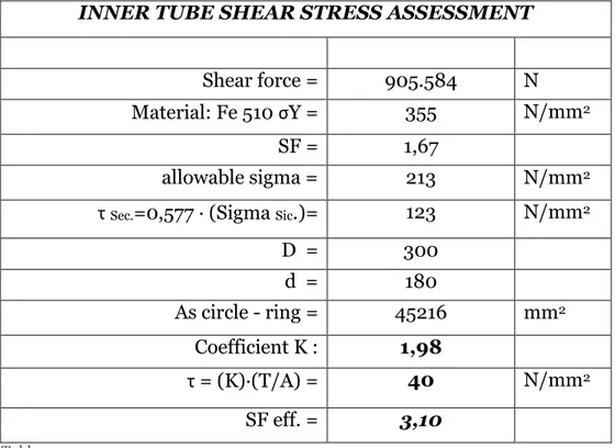
On the spreadsheet on which the project has been developed continues with a section assigned to the shear assessment of the two tubes, to verify the correct dimensioning also with respect to the shear force due to the bending moment acting on the structure.
INNER TUBE SHEAR STRESS ASSESSMENT
Shear force = 905.584 N
Material: Fe 510 σY = 355 N/mm2
SF = 1,67
allowable sigma = 213 N/mm2
τ Sec.=0,577 · (Sigma Sic.)= 123 N/mm2
D = 300 d = 180 As circle - ring = 45216 mm2 Coefficient K : 1,98 τ = (K)·(T/A) = 40 N/mm2 SF eff. = 3,10 Table 3.7
Table 3.7 accounts for the data and calculations performed for the shear assessment of the inner tube, while Table 3.8 refers to the outer tube.
49
OUTER TUBE SHEAR STRESS ASSESSMENT
Shear force T= 905.584 N
Material: Fe 510 σY = 355 N/mm2
SF = 1,67
allowable sigma = 213 N/mm2
τ Sec.=0,577 · allowable sigma = 123 N/mm2
D = 360 d = 305 A = 28711 mm2 Coefficient K : 1,99 τ = (K)·(T/A) = 63 N/mm2 SF eff. = 1,96 Table 3.8
In this section, as for the bending assessment, the allowable sigma has been obtained dividing the Yielding strength of the material by the minimum safety factor required provided by the field experience, equal to 1,67. The parameters reported in Table Table have been calculated as follows:
𝐴 =
cross − sectionalarea = π(𝐷2 − 𝑑2) ∙ 1 4 𝜏𝑠𝑒𝑐 = 0,577𝜎𝑎𝑙𝑙𝑜𝑤𝑎𝑏𝑙𝑒 𝜏 = 𝐾𝑇 𝐴 𝑆𝐹𝑒𝑓𝑓 =𝜏𝑠𝑒𝑐 𝜏50
3.5 Bearings assessment
The final part concerning the development of the innovative suspension system regarded the bearings for the coupling of the two tubes.
After the analysis of several alternatives the choice fell upon the two bushing, also referred to as plain bearings, because of the fact that plain bearings, in general, are the least expensive type of bearing. They are also compact and lightweight, and they have a high load-carrying capacity.
The choice of the bushing started from the analysis of various catalogues of the Drillmec’s suppliers, and the most reliable was found out to be Trelleborg.
Trelleborg si specialized in the development of bushings with the purpose of guiding metallic parts moving relatively avoiding their contact.
At the beginning, the plain bearings have been dimensioned starting from the catalogue and the relative tables and graphs. After this preliminary dimensioning, the supplier of the bearings has been contacted in order to ensure a correct assessment of the bearings; the assessment has been performed following the formulae provided and checked by the supplier.
51
Figure 3.6 guide for dimensioning of standard plain bearings
In Table are reported the calculations performed for the final assessment of the lifting system’s bearings, where the surface on which the radial force acts is calculated with the formula:
𝑆𝑢𝑟𝑓𝑎𝑐𝑒 = 𝐷 ∙ 𝑇 ∙𝜋 4
That is the lateral surface divided by four, since the actual contact area is one fourth of the total surface area. The stress acting on the bearing has been evaluated as:
𝜎 = 𝐹𝑜𝑟𝑐𝑒
𝑆𝑢𝑟𝑓𝑎𝑐𝑒
Allowing to estimate the safety factor as:
𝑆𝐹 =𝜎𝑚𝑎𝑥
52
It can be noticed that, with a safety factor equal to 7,54, the bearings have been correctly dimensioned and guarantee room enough in the case that the actual load increases. The calculations have been performed considering a distance of 30 mm between the nearest surfaces of the bearings when the cylinder is fully open. In this way we are sure that, when it is required to exploit the lifting system at its maximum extent, the bearings do not hit themselves.
BEARING ASSESSMENT distance = 30 mm force = 905.584 N d = 300 mm Tmin= 29 mm T = 100 mm Surface = 23.550 mm2 σ= 38 N/mm2
Bush's yield strength=σmax= 290 N/mm2
SF= 7,54
Table 3.9
3.6 Suspension system’s 3D models
The dimensioning and assessment of the bearings have been the last step of the development of the new PCT’s suspension group before the 3D modelling of all the elements composing the system. The dimensions of the elements have been verified and, unless slight adjustments that could be provided in order to facilitate the mounting sequences, are the one previously reported in the tables of the chapter.
53
The models are reported in the images below, and have subsequently been mounted on the rig to analyse the positioning of the PCT on the floor.
54
57
Chapter 4: Improvement on Handling group
As soon as the design of the new suspension group was completed, the second step of the study of innovation of the new PCT began. This step consisted in the study of a possible solution to substitute the robotic arm of the PCT, that has the scope of displacing horizontally the PCT with the purpose of making it reach the centre well when in parking configuration and vice versa.
The aim of the study of innovation, as for the suspension group, is to develop a new solution reducing the encumbrances, guaranteeing the performances provided by the previous technology and, if possible, simplify the system, in order to guarantee a fast and easy mounting sequence.
For this assembly, it was impossible to manipulate the positioning of the PCT in order to exploit empty spaces of drill floor as it has been done for the suspension group, so it became mandatory to ensure a compact configuration of the new arm when the PCT is in parking configuration guaranteeing, at the same time, at least the same performances oh the previous one.
After the study of several alternatives, the final choice felt upon the first idea concerning the lifting group: a telescopic actuator with a telescopic guide.
With such a design it was ensured a compact and light structure, with a simple and easy-to-assemble configuration. The first solution that was studied started from the idea of dividing the arm in three stages, with a linear guide whose central part consisted of two linear guide put together welding their back surfaces. This configuration was subsequently rejected since it would have required to slightly increase the length and the width of the arm, reducing the benefits of the new arm.
58
Therefore, the configuration was change, keeping just one guide for the central stage, reducing the width of the arm up to the total width of the clamp group of the PCT, that is the minimum width obtainable.
4.1 Handling group components
The group is composed by an actuator, that is a telescopic hydraulic piston, the horizontal telescopic guide, made up of three segments, and the bearings that allow the sliding of the segments composing the guide.
4.2 Bearings choice and assessment
The project concerning the new arm started from the dimensioning of the guide, that is the component that has to meet more constraints. First of all, the guide must be compact when close and, at the same time, ensure that, once is fully open, the PCT can reach the centre well even in the worst situation, which is those rig where it is necessary to mount the PCT further from the centre well. Moreover, the guide must be as much as slim as possible in order to keep the weight subdued and, at the same time, it must be strong enough to support the weight of the PCT. Another important constraint is the width of the guide, that must be as small as possible to have the most compact configuration obtainable, that can yield a clear advantage with respect to the competitors.
The dimensioning, as it was done for the lifting group, started from the evaluation of the weights and the distances of the centres of mass from the column of all the groups of the former PCT, extracted with the software Creo Parametric.
59
The project of the new arm required at the beginning the choice of the bearings. This step has been performed first because the dimensions of the bearings must be known in advance so that the guide could be dimensioned properly.
For the choice of the bearings CR srl, one of the main supplier of Drillmec, has been contacted in order to find the bearing that could better meet our needs.
C.R. is an Italian company specialised in the manufacturing of special roller bearings for industrial applications and internal movement plants and equipment, manufactures both special bearings according to its exclusive project, following the requirements of the customers, and perfectly interchangeable spare parts, according to the customers' drawings or samples.
The bearing has been chosen among those contained in the CR srl’s rolling bearings catalogue, and the choice fell upon the CR 400-0091, belonging to the series of the adjustable combined bearings Jumbo due to their high load capacity and restrained dimensions, and is defined by the following characteristics:
The pivot (4), external ring (5), and roller (6) are realized in steel 16CrNi4, a material that ensures a significant resistance making it especially suitable to sustain impacts and high applied loads. The components can reach a hardness equal to 60-2 HRC.
The internal ring is realized in steel 100Cr6 reaching a hardness equal to 60+2 HRC
They can be provided with a running capacity ZZ or 2RS and have a lubrication system in the radial part
The backup slewing (2) is realized in case-hardened steel
The pivot (4) is realized in 16CrNi4, that guarantees its extraordinary resistance to fatigue and making it easy to weld.
60
Figure 4.1 Bearing's components
The dimensions of the bearing are reported in Table and shown in Figure 4. where it is also suggested the best guide produced by CR srl to optimize the performances of the chosen bearing.
FM 220 is the suggested guide for our bearings, that is a compound I-shaped guide. However, the suggested guide has been discharged after a preliminary analysis of the design of the telescopic guide because it would have led to an increase to the width of the PCT to ensure a correct assembly of the new system. In order to avoid the increase in dimensions, it has been studied the development of a new guide that can ensure the same performances of the I-shaped keeping restrained dimensions also when assembling.
61
Figure 4.2 bearing section and dimensions
62
The step that followed the choice of the bearings was, after the preliminary examination, the verification that the bearings could withstand the load acting on them. To perform the assessment of the bearings it was initially necessary to model the guide and the bearings, in order to obtain a correct scheme of the forces acting on the system. The operating principle of the guide is known in advance so, even if the guide was not designed yet, the acting forces could be modelled. The forces acting on the bearings where calculated considering the telescopic guide fully open, when the load due to the PCT’s weight as far away from the PCT’s basement as possible, generating the highest moment. The assessment was carried out considering that the guide is in fact a double-guide, since there is a linear telescopic guide for both the sides of the PCT, and a single bearing set on each segment of the guide, bringing the total number of bearings to 6, 3 for each side. With this design when the telescopic guide is fully open the most strained bearings are the ones mounted on the first segment of the guide and on the second segment. The first segment is the one coupled with the rotation group of the PCT and in fact the only one that never moves, while the second segment is the middle one. The bearings coupling has been developed in the best way to minimize the encumbrances of the PCT, leading to a configuration that considers the bearings of the two sections far from each other when the guide is closed while they get closer as long as the guide is open.
Therefore, for the guide’s operating principle, when the PCT is in the centre well the distance between the two bearings is just the clearance between them.
In Figure is reported the model generally adopted to evaluate the forces acting on the bearings, where:
Fwz is the force acting on the system in the z direction
Fwy is the force acting on the system in the y direction
63
Fyn2 is the resultant load acting in the y direction on the most distant bearing from force’s application point.
Fzn2 is the resultant load acting in the z direction on the most distant bearing from force’s application point.
Fyn1 is the resultant load acting in the y direction on the nearest bearing from force’s application point.
Fzn1 is the resultant force acting in the z direction on the nearest bearing from force’s application point.
Mxn1=Mxn2 is the resultant moment.
Lw is the distance between the centres of gravity of the bearings
xw is the distance of the load’s application point from the plan defined by axis y and z
yw is the distance of the load’s application point from the plan defined by axis x and z
zw is the distance of the load’s application point from the plan defined by axis y and x
64
Figure 4.3 Guide model
And the loads, acting on the guides, can be calculated as:
𝐹
𝑧𝑛1=
∑ 𝐹𝑤𝑧,𝑗 𝑘 𝑗=1 2−
∑𝑘𝑗=1(𝐹𝑤𝑥,𝑗∙(𝑧𝑤,𝑗−𝐿𝑧))−∑𝑘𝑗=1(𝐹𝑤𝑧,𝑗∙𝑥𝑤,𝑗) 𝐿𝑤
𝐹
𝑧𝑛2=
∑ 𝐹𝑤𝑧,𝑗 𝑘 𝑗=1 2+
∑𝑘𝑗=1(𝐹𝑤𝑥,𝑗∙(𝑧𝑤,𝑗−𝐿𝑧))−∑𝑘𝑗=1(𝐹𝑤𝑧,𝑗∙𝑥𝑤,𝑗) 𝐿𝑤
𝐹
𝑦𝑛1=
∑ 𝐹𝑤𝑦,𝑗 𝑘 𝑗=1 2−
∑𝑘𝑗=1(𝐹𝑤𝑥,𝑗∙(𝑦𝑤,𝑗−𝐿𝑦))−∑𝑘𝑗=1(𝐹𝑤𝑦,𝑗∙𝑥𝑤,𝑗) 𝐿𝑤65
𝐹
𝑦𝑛2=
∑ 𝐹𝑤𝑦,𝑗 𝑘 𝑗=1 2+
∑𝑘𝑗=1(𝐹𝑤𝑥,𝑗∙(𝑦𝑤,𝑗−𝐿𝑦))−∑𝑘𝑗=1(𝐹𝑤𝑦,𝑗∙𝑥𝑤,𝑗) 𝐿𝑤
𝑀
𝑥𝑛1= 𝑀
𝑥𝑛2=
∑ (𝐹𝑤𝑧,𝑗∙ 𝑘 𝑗=1 𝑦𝑤,𝑗)−∑𝑘𝑗=1(𝐹𝑤𝑦,𝑗∙𝑧𝑤,𝑗) 2Where j is the index identifying the k forces acting on the system. In our model the index k is equal to one since the only force acting on the PCT is its own weight, leading to a simplification of the equations. The so obtained loads must be compared to the dynamic load of the bearings, to be sure that they can sustain the PCT during the tasks it has to fulfil.
Bearing characteristics and assessment - CR 400-0091
Bearing Diameter D= 220 mm
Dynamic load C= 326 kN
Static load C0= 681 kN
Clearance g 200 mm
Distance between bearings' centres Lw 420 mm Force's application point yw 0 mm
zw 0 mm xw 2430 mm Load on bearing 1 Fzn1 244304,0357 N 244,3040357 kN Load on bearing 2 Fzn2 208301,3357 N 208,3013357 kN SF1 2,78 SF2 3,26
Table 4.2 bearing's assessment
In Table 4.2 are reported the characteristics of the bearings needed for their assessment. The clearance between the two bearings has chosen
66
with an iterative method to find out the best value that ensures the lowest load on the bearings keeping a compact layout. As it can be seen in the table, a clearance of 200 mm between the two bearings guarantees that the bearings are not stressed too much, keeping the working conditions far enough to critical values.
The calculations ensured that the chosen bearings could fulfil their assignment, leading to the next step of the project, the dimensioning of the guide.
4.3 Guides dimensioning
In this section is outlined the dimensioning and assessment of the guides on which the bearings will run. This step, that comes soon after the choice of the bearings, is has become necessary inasmuch as the guide suggested by the bearings’ manufacturer did not meet the imposed constraints.
The choice of the profile fell upon the C-shaped guides, that have been designed in the company Drillmec and, subsequently, their feasibility has been verified by the manufacturing company.
The constraints, for the dimensioning of the guide, are the necessity of a compact but tough section and the inner section that must allow a correct installation of the bearings.
Once that the dimensions where determined it has been possible to verify whether the guide was assessed or not. In Figure 4.4 is represented the guide’s profile while, in Table 4.3, all the dimensions and the assessment are reported.
67
Figure 4.4 Guide profile
Guide's profile dimensioning
b2 220,00 mm b1 45,00 mm b 310,00 mm h1 40,00 mm h 105,50 mm J 203.792.208,33 mm4 W 1314788,441 mm3 σ= 66,5404093 N/mm2 σY = 355 N/mm2 SF 5,32
Table 4.3 guide dimensions and assessment
In this situation, the guide dimensions have been chosen with an iterative method to find out the slimmest guide that guarantees a safety factor high enough.
Chosen the dimensions, it has then been possible to evaluate the moment of inertia of the cross-section with the formula:
68 𝐽 =ℎ ∙ 𝑏
3− (ℎ − ℎ 1) ∙ 𝑏23
12
The moment of inertia of the cross-section J has been used to calculate the elastic section modulus as:
𝑊 = 𝐽
(𝑏2)
That is applied to the evaluation of the stress acting on the guide, that has been compared to the yield strength σy of the guide, equal to 355
N/mm2 (MPa) in order to calculate the safety factor. The formulae adopted are:
𝜎 =
𝐹
𝑤𝑧∙ 𝑥
𝑤𝑊
𝑆𝐹 =
𝜎
𝑦𝜎
As it can be seen in Table 4.3 a high the safety factor is guaranteed, meaning that the guide is strong enough to sustain the PCT.
A further assessment that needs to be performed is the local girder stress assessment. This part of the project is mandatory because of the fact that the flange bending stresses arise as secondary stresses around of the load application point in the girder, disregarding the girder’s supporting structure.
For the assessment of the flanges, the method expounded in FEM 9.341 section 9 is adopted.
69
Figure 4.5 Inclined flanges
Figure 4.6 Parallel flanges
Figure 4.5 and Figure 4.6 illustrate the two possible alternatives of the flanges’ profile, using as samples the “I” profile, in our project the parallel flanges were chosen but, for the sake of completeness, are reported also the equations to fulfil the assessment also for the girder with inclined flanges.
The stresses acting on the flanges can be calculated with the following formulae:
𝜎
𝐹𝑥= 𝑐
𝑥𝑅
𝑡
𝑖2𝜎
𝐹𝑧= 𝑐
𝑧𝑅
𝑡
𝑖270 Where:
𝑐𝑥 and 𝑐𝑧 are two coefficients, separately determined,
dependent on the load position i, or λ;
R is the maximum bearing load
ti is the theoretical thickness of the flange at the load position i
i is the distance of the load application point from the girder edge
The coefficients 𝑐𝑥 and 𝑐𝑧 have been established by means of numerous
tests performed; the theoretical investigation of particular results was performed with the help of the finite element method, have confirmed largely concomitant. The coefficients need to be evaluated in three different marked points on the flange, indicated in Figure 4. and Figure with the numbers 0,1 and 2, where point 0 expresses the transition web/flange, point 1 is the load application point and, finally, point 2 is the edge of the flange. The equations that determine the coefficients are:
Girder with parallel flanges - Figure
𝑐
𝑧0= 0,05 − 0,58 ∙ 𝜆 + 0,148 ∙ 𝑒
3,015∙𝜆
𝑐
𝑧1= 2,23 − 1,49 ∙ 𝜆 + 1,390 ∙ 𝑒
−18,33∙𝜆
𝑐
𝑧2= 0,73 − 1,58 ∙ 𝜆 + 2,910 ∙ 𝑒
−6∙𝜆
𝑐
𝑥0= −2,11 + 1,977 ∙ 𝜆 + 0,0076 ∙ 𝑒
6,53∙𝜆
𝑐
𝑥1= 10,108 − 7,408 ∙ 𝜆 − 10,108 ∙ 𝑒
−1,364∙𝜆
𝑐
𝑥2= 0
Girder with inclined flanges - Figure 4.