ISTITUTO NAZIONALE DI FISICA NUCLEARE
Sezione di BolognaINFN/TC-10/05 June 25, 2010
THE CANTES EXPERIMENT: A CARBON NANOTUBES BASED
ELECTRON GUN TO IMPROVE THE PERFORMANCES OF THE
ELECTRON CYCLOTRON RESONANCE ION SOURCES
F. Odorici1, M. Cuffiani2,1 , L. Malferrari1 , R.Rizzoli3,1 , G. P. Veronese3,1 , S. Gammino4 , L. Celona4 , D. Mascali4,5 , N. Gambino4,6 , R. Miracoli4,7 , G. Castro4,7 , F. P. Romano4,8 , T. Serafino9 , F. Di Bartolo9 , V. Guglielmotti10 , S. Orlanducci10 , V. Sessa10 , M. L. Terranova10 1INFN, Sezione di Bologna, Viale B. Pichat 6/2, 40127 Bologna, Italy
2
Dipartimento di Fisica, Università di Bologna, Viale B. Pichat 6/2, 40127 Bologna, Italy
3
Istituto per la Microelettronica ed Microsistemi del CNR, Via Gobetti 101, 40129 Bologna, Italy
4
INFN - Laboratori Nazionali del Sud, via S. Sofia 62, 95123 Catania, Italy
5
Centro Siciliano di Fisica Nucleare e Struttura della Materia, V.le A. Doria 6, 95125 Catania, Italy
6
Università degli Studi di Catania, Dipartimento di Metodologie Fisiche e Chimiche per l’Ingegneria, Viale A. Doria 6, 95125 Catania, Italy
7
Università degli Studi di Catania, Dipartimento di Fisica e Astronomia, V. S. Sofia 64, 95123 Catania, Italy
8
CNR-IBAM, c/o Palazzo Ingrassia, Via Biblioteca 4, 95124 Catania, Italy
9
Università di Messina, Ctr.da Papardo-Sperone, 98100, Messina, Italy
10
Dipartimento di Scienze e Tecnologie Chimiche, MINASlab, Università di Roma “Tor Vergata” – INFN, via della Ricerca Scientifica, 00133 Roma, Italy
Abstract
The increase of electron density in ECR ion sources assures efficient ionization of very low-gas-pressure plasma. The purpose of this experiment was the creation of a carbon nanotubes based electron gun, in order to inject electrons in the plasma core and to follow how the charge state distribution and the X-ray spectra change. The use of carbon nanotubes leads to an increase of the plasma density and to a relevant reduction of the number of high energy electrons, which are detrimental for the reliability of the modern ECRIS.
PACS.: 52.50.Sw, 81.07.De
Presented at the 12th Topical Seminar on Innovative Particle and Radiation Detectors (IPRD10), 7 - 10 June 2010, Siena, Italy
Published by SIS–Pubblicazioni Laboratori Nazionali di Frascati
1 INTRODUCTION
One of the crucial issues in ECR ion sources (ECRIS) operating with B-minimum magnetic structures consists in the so-called electron starvation 1). Although plasmas in B-min configurations are magneto-hydro-dynamically stable, electron losses may be large enough to deteriorate the source ability to generate large numbers of highly charged ions in short times. It is then necessary to supply auxiliary electrons to the magnetic trap, in order to obtain an electron density large enough for efficient ionization inside the low-gas-pressure plasma. Biased disks are usually employed for this purpose 2), as they are able to recover a large fraction of axially escaping electrons.
Here we propose an alternative method to provide additional electrons to the plasma core, i.e. the use of carbon nanotubes (CNTs) which emit in presence of electric fields. The effect of these additional electrons is that to improve the plasma dynamics, and hereinafter the variations of the extracted charge state distribution and of ray spectra will be shown. X-rays are in fact emitted by the electrons in the plasma core, as Bremsstrahlung radiation. The investigation of X-ray spectra gives some insights on the energy content of plasma particles, and in particular the generation of high energy electrons (> 100 keV): they are detrimental for ECRIS not only because they have a low ionization cross section, but also because they heat the helium cryostat containing the superconducting magnets of the most recent ion sources 3). The damping of the mechanisms leading to strong electron heating is thus one of the crucial tasks of modern ECRIS science, because any further development of these devices depends on the ability to perfectly tailor the electron energy distribution function, maximizing the number of those particles whose energies allows effective ionization cross section (1-100 keV).
2 EXPERIMENTAL SET-UP
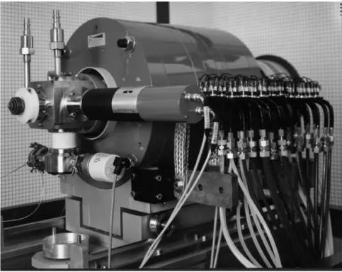
The ECR ion source CAESAR 4) is operating at INFN-LNS laboratories as injector of the K-800 Superconducting Cyclotron since 2000 (Fig. 1). The body source consists of a water-cooled inox plasma chamber, where the ionization is obtained by means of a 14 to 18 GHz RF generator. The magnetic system is composed, for the axial confinement, by two coils, independently energized, which can generate a magnetic field greater than 1.5 T. For the radial confinement a sextupole, Nd-Fe-B permanent magnet, has been used with maximum field equal to 1.1 T. A three electrode extraction system, able to operate up to a maximum voltage of 30 kV is used for the beam formation, and a biased disk is used to enhance the electron density. The main features of CAESAR are described in a previous paper 4).
In the past, several passive techniques for the injection of secondary electrons have been tested at INFN-LNS, with the purpose to extend the plasma ion lifetime and to increase the ionization probability. For those methods, passive materials act as electron donors. For example, an alumina disk allowed improving ECRIS performances, because of a high rate of secondary electrons emitted by alumina, even at low energy of primary electrons 5).
Active materials, like ferroelectric cathodes, such as PBZT doped with 2 % of Bi2O3, have been employed because of their capability of producing high emission yields of energetic electrons 4) 6). However, their robustness has shown to be not sufficient for stable applications into ECRIS. In fact, the ferroelectric cathodes showed not only a lack of reliability, but also a little resistance to plasmas, and they failed after short time.
FIG. 1: The CAESAR source at INFN-LNS
Active materials, like ferroelectric cathodes, such as PBZT doped with 2 % of Bi2O3, have been employed because of their capability of producing high emission yields of energetic electrons 4) 6). However, their robustness has shown to be not sufficient for stable applications into ECRIS. In fact, the ferroelectric cathodes showed not only a lack of reliability, but also a little resistance to plasmas, and they failed after short time.
With this experiment, a new active technique which makes use of CNTs-based electron guns to inject electrons into the plasma has been tested. The most important components of the electron gun are the CNTs emission cathode and the anodic grid. More details on the gun elements are given in the next paragraph. In our set-up, two electron guns are placed on a copper plate connected to the RF waveguide that is usually employed as bias disk in the CAESAR source. A potential in the range 0-2.5 kV, is then applied between the chamber and the waveguide, and the same potential is used to produce the emission field (i.e. the extraction field) between CNTs and the anodic grid.
During the test we were able to measure the current given from the bias power supply to the electron guns circuitry. This corresponds to the current emitted by the CNTs, plus the ionization of the residual gas between the anodic grid and the CNTs, plus the contribution of
positive ions escaping the plasma confinement and impinging on the RF waveguide. Therefore, only part of the measured current corresponds to additional electrons that may reach the plasma region, and at this time we are not able to determine how large this fraction is. Ions are extracted from CAESAR with a kinetic energy equal to 20 keV per charge state, then focused by a solenoid and deflected by a 90° dipole magnet in order to be analyzed with a Faraday cup located at its image point. In our application we inject krypton mixed with helium. The current intensity of all Kr charged states have been monitored during the experiment and the Kr11+ current has been used as reference.
2.1 The carbon nanotubes based electron gun
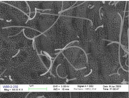
The CNTs electron gun is essentially made of three elements: a CNTs cathode obtained on a 300 µm thick silicon substrate, a 150 µm thick mica spacer and an anodic copper grid with quad cells of 350 µm side. CNTs eject electrons because of the field emission effect, i.e. quantum tunneling, which is obtained by applying an electric field higher than 3-4 V/µm. Details on CNTs preparation and their field emission properties will be given in a separate paper 7). Here it is worth to mention that the adopted CNTs samples are obtained from several building steps. A thick layer (few microns) of aluminum is evaporated on a silicon wafer. Aluminum is then electrochemically converted to a highly regular porous anodic aluminum oxide, with 100 nm pore pitch and 80 nm pore size. At the bottom of the pores is then electrochemically deposited a small amount of cobalt, and CNTs have been synthesized by means of a Catalyst-assisted Chemical Vapour Deposition (C-CVD) process at atmospheric pressure, in a quartz hot-wall furnace at 620 °C. In such a process, multiwall CNTs are obtained having the same diameter of the alumina pores, i.e. 80 nm. Some of the CNTs exit the alumina surface and can reach a total length of 5-10 µm. A field emission-scanning electron microscopy (FE-SEM) image of a typical CNTs sample is shown in Fig. 2.
FIG. 2: SEM plan-view of the surface of a typical CNTs sample. Some CNTs exit the alumina pores and can reach a total length of some microns.
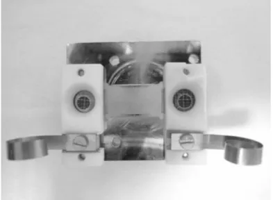
The gun elements are kept together by a MACOR (machinable glass ceramic) holder, on which the electrical connection is obtained by an evaporated gold track. The MACOR holder is then fixed on a copper plate, i.e. the bias disk of the source, connected to the waveguide of the plasma chamber. The anodic grids are linked to the ground potential of the plasma chamber wall by means of copper creeping contacts. Two of such electron guns were mounted on the same bias disk during the experimental tests. Pictures of a CNTs sample and the assembled guns are shown in Figures 3 and 4. Note that the “bias disk” 2) is normally used in CAESAR at low positive potentials (100-300 V) in order to reflect part of the low energy electrons escaping from the magnetic trap and to add more electrons with energy suitable for ionization . In our setup the bias potential is boosted up to 2.5 kV in order to operate with the CNT based guns.
FIG. 3: Left: a CNTs sample and a mica spacer (with a 4 mm central hole) on it. Right: the MACOR holder keeps together the grid, the mica spacer and the CNTs sample.
FIG. 4: The CAESAR bias disk, holding two CNTs electron guns. The copper creeping contacts are used to set the extraction grid to the same potential of the chamber, while the
Prior to the plasma test, each CNTs sample was tested in terms of field emission, by means of a custom-designed apparatus 8). The field emission properties of similar samples (i.e. CNTs arrays in free-standing porous alumina foils) were already tested 9) and found to be able to produce current densities up to 10-40 mA/cm2. Emission measurements for the samples tested in CAESAR (i.e. CNTs arrays in porous alumina on silicon), gave even better results, with current densities up to 50-100 mA/cm2, as will be reported in a separate paper 7). The emission surface in our samples was set to about 0.1 cm2, by using a mica spacer with a 4 mm diameter central hole (Fig. 3).
2.2 The X-rays measurements
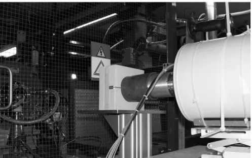
The measurements of X-rays emitted by the CAESAR’s central plasma region have been carried out by using an HPGe detector (High Purity Germanium), collimated through lead shielding blocks, in order to suppress secondary X-rays coming from electrons impinging on the lateral walls of the plasma chamber. The detector was surrounded by additional lead in order to minimize the leakage of the X-ray radiation around the main collimator. The collimation hole was 1 mm2, i.e. smaller than the microwave port located at the injection flange of the CAESAR source. Fig. 5 shows a sketch of the experimental apparatus. The detector is particularly suitable for the detection of X-rays in the range of tens and hundreds keV; the energy calibration was done by using an 152Eu source.
FIG. 5: The X-ray detector, a HPGe type solid state detector, is collimated with respect to the axis of the ECRs
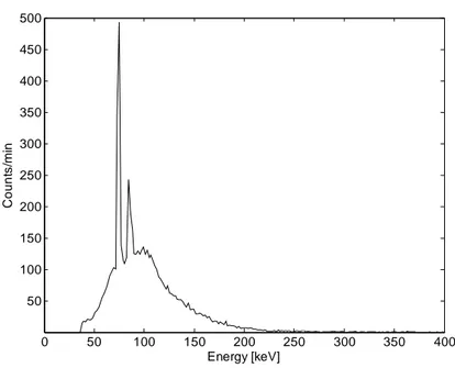
A typical axially emitted X-ray spectrum is shown in Fig. 6. In the spectrum, two peaks at 74.22 and 84.86 keV can be observed, corresponding to characteristic X-rays emitted by lead.
ource.
FIG. 6: Axially emitted X-ray spectrum for a plasma with 100 W RF power.
3 RESULTS AND DISCUSSIONS
At an earlier stage, CNTs samples of the same type as used for CAESAR have been tested in microwave discharge plasma (MDIS), in order to preliminary verify if electron and ion collisions can damage them. The adopted MDIS apparatus operates at 2.45 GHz and generates, in presence of an off-resonance magnetic field, a weakly ionized and strongly collisional plasma because of low electron temperature (Te<10 eV) and high pressure (0.4 mbar). Tests were made both for air plasma and nitrogen plasma. Results were collected in 2008 and showed that CNTs exposed to intense plasma milling (up to 4 mA/cm2 current density and 300 C/cm2 of integral dose) have been merely damaged in presence of oxygen (air plasma) but were perfectly resistant to nitrogen plasma. After the response of this preliminary test-bench, CNTs cathodes have been used for tests in ECR ion sources.
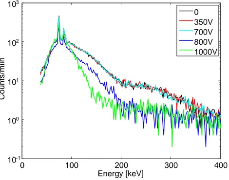
With the above described CAESAR set-up, we inserted two CNTs electron guns and measured the axially emitted X-ray spectra for different CNTs applied voltages, as shown in Fig. 7. We can observe that the spectrum remains unchanged when voltages are below 700 V. At these applied voltages the wide region in the energy range 200-350 keV is influenced by an insufficient collimation of the detector, which presents pile-up due to the most energetic electrons striking against the injection flange of the chamber.
Anyway the existence of this tail is a clear sign of high energy electrons generated in the plasma core. As we increase the CNTs applied voltage up to 800 V, the tail produced by the higher energy electrons disappeared (especially in the energy range 200 - 350 keV). Although the not perfect collimation of the detector cannot permit to extrapolate quantitative estimations on electron spectral temperature, it is however evident that the energy content of the hottest electron component decreases.
0 50 100 150 200 250 300 350 400 50 100 150 200 250 300 350 400 450 500 Energy [keV] Co un ts /m in
FIG. 7: Axially emitted X-ray spectra for different CNTs applied voltages, at RF power of 100 W
By increasing the CNTs applied voltage, one can observe that the Bremsstrahlung peak becomes narrower: in other words, by providing additional electrons to the plasma, the energy per single particle decreases; a larger number of electrons will share the same amount of energy injected into the plasma chamber by means of the microwave (the RF power is kept constant).
As mentioned before, if we suppose that in the plasma there are thermal electrons (distributed according to the Maxwell-Boltzmann distribution with the temperature Te), we can deduce the electron temperature by making the linear fit of Bremsstrahlung spectra. The slope of this fit is inversely proportional to the electron temperature. From a qualitative analysis we can say that the electron temperature decreases when the CNTs applied voltage increases, or rather when the amount of electrons provided by CNTs increases.
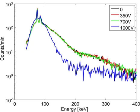
The same results were obtained by applying a RF power of 150 W (Fig. 8). Anyway, in this case, the effect of additional electrons was evident at larger extraction voltages. Because of the peculiarities of the CNTs-based electron gun, the number of injected electrons increases with the voltage, and this explains the necessity to increase the voltage in order to damp the generation of high energy electrons when using larger RF power: more electrons are needed to share an increased amount of power than in case of low RF power.
0 100 200 300 400 10-1 100 101 102 103 Energy [keV] Counts/miin 0 350V 700V 800V 1000V
FIG. 8: Axially emitted X-ray spectra for different CNTs applied voltages, at RF power of 150 W.
The use of CNTs emitted electrons provided many benefits also to the production of several charge states. Initially we focused our attention to the current increase of a single charge state (Kr11+), and then we proceeded with the analysis of the entire Charge State Distribution (CSD) spectrum. Fig. 9 shows the trend of the extracted current of Kr11+ when the CNTs emission is switched on and off, in a time window of 30 seconds.
FIG. 9: Trend of the Kr11+ current during the switching on-off of CNTs emission, in a time window of 30 seconds. The CNTs applied voltage was 2500 V, at 35 W RF power.
0 100 200 300 400 10-1 100 101 102 103 Energy [keV] Counts/min 0 350V 700V 1000V 1 0 . 0 0 . 0 2 . 0 4 . 0 6 . 0 8 . 0 K r 11+ current [µ A ]
The “jump” of extracted current, which takes place immediately after the electron emission from CNTs, is evident in the Fig. 9 and it was obtained with 2500 V applied to the CNTs extraction grid. It is also interesting to note the afterglow-like peak when the electron gun is going to switch off. The gain of current is almost 60 % and reaches 100 % during the afterglow peak, at an RF power of 35 W.
It is even more interesting to compare the CSD when using the carbon nanotubes at different extraction voltages. In Fig. 10 the measurements carried out at about 100 W RF power with 0, 700 and 800 V of extraction voltage are shown. Already at 700 V the increase of Kr current when CNTs emission starts is evident. Not only the hot electrons temperature decreases with the applied voltage, but this also occurs for the warm population, i.e. for those particles responsible of the large amount of ionization process: their temperature can be estimated by looking to the CSD, whose charge state at maximum current has a ionization potential approximately equals to 1/3 of the warm electron temperature. This temperature decrease is evident in Fig. 10: note that the CSD peak slightly shifts to lowers charges states by increasing the extraction voltages on the nanotubes, i.e. by increasing the number of electrons injected into the plasma. This observation may be misleading, because we would expect a larger average charge state due to a bigger quality factor that is given by the product between the electron density ne and the ion confinement time τi (the ion lifetime should be unchanged, while the electron deficit is compensated by the increase of the electron density). The explanation may be found in the local “cooling” of the plasma electrons, following the absorption of sub-keV electrons.
500 600 700 800 900 1000 1100 1200 1300 1400 0 2 4 6 8 10 12 14 16 18 20 22 H2+ O5+ O4+ O3+ O2+ 8+ 9+ 10+ 11+ 12+ 13+ 14+ 15+ Cu rren t [ µΑ ] B[G] CNT 0 V CNT 700 V CNT 800 V
FIG. 10: Charge state distribution, optimized for Kr11+ at about 100 W, for different CNTs applied voltage.
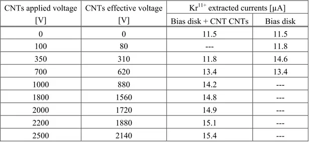
In Tab. 1 the Kr11+ extracted currents have been reported for different CNTs applied voltages, at a constant RF power of 100 W. Extracted currents can be compared with those obtained when the CNTs electron gun was switched off: the maximum current value (15.4 µA) has been obtained for a CNTs applied voltage of 2500 V. Note that what we call “CNTs applied voltage” is not the “CNTs effective voltage”, because the gun circuitry has a 0.5 MΩ series ballast resistor. The CNTs effective voltage is obtained by subtracting the voltage drop on the ballast resistor, as shown in Tab. 1. In the same table we also report values of currents obtained with the bias disk only, i.e. the biask disk without electron guns (no CNTs and no MACOR) mounted on it. In this case the bias effective voltage corresponds to the applied voltage.
TAB. 1: The Kr11+ extracted currents at different bias voltages, at 100 W RF power, for CNTs and for bias disk only
Kr11+ extracted currents [µA] CNTs applied voltage
[V]
CNTs effective voltage
[V] Bias disk + CNT CNTs Bias disk
0 0 11.5 11.5 100 80 --- 11.8 350 310 11.8 14.6 700 620 13.4 13.4 1000 880 14.2 --- 1800 1560 14.8 --- 2000 1720 14.9 --- 2200 1880 15.1 --- 2500 2140 15.4 ---
Current improvements obtained with the CNTs-based electron gun can be compared with those observed when using the bias-disk alone (see figure 11). To the latter we applied potentials ranging from 35 to 720 V. It can be deduced from figure 11 that at bias voltages larger than 350 V the extracted current drastically decreases. Conversely, the current is boosted by CNTs for voltages higher than 750 V and then it increases monotonically, slowly approaching to saturation above 1000 V. But CNTs provide additional and even more important benefits to ECR plasmas: as seen above they contribute to the total suppression of the hot electrons component, that is evident above 1000 V. The same effect is not evident when using a conventional biased disk, at least up to the maximum employed voltage. We did not further increase the voltage on the bias disk because of the already evident deterioration of performances at 720 V. Also note that at low potential (200-500 V) the bias disk effect, when CNTs are present, appears to be reduced. This is probably due to the fact that the gun elements (i.e. the MACOR holder) reduce the effective surface of the bias disk.
FIG. 11: comparison of produced Kr11+ current when using conventional biased disk or emitting CNTs. The current has been normalized to its maximum value.
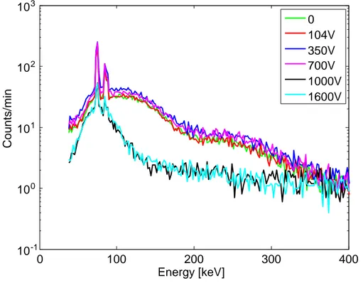
FIG. 12: Axially emitted X-ray spectra for different voltage values and RF power of 30W.
0 100 200 300 400 10-1 100 101 102 103 Energy [keV] Counts/min 0 104V 350V 700V 1000V 1600V 0 500 1000 1500 2000 2500 0 5 10 15 20 25 30 35 40
Effective applied voltage (V)
Enha ncem ent of K r 11 + curr ent (% )
bias disk only
We also report some measurements at extremely low power levels, around 30 W (Fig. 12). These RF power are usually too low for plasma heating in CAESAR, with modest performances in terms of charge states and currents.
Anyway, measurements at such low power level demonstrate once again that the lower is power, the more important will be the contribution of CNTs to the improvement of the plasma quality (first of all the damping of hot electron generation mechanism). In the measurements carried out at 30 W, for voltage values higher than 1000 V, one can observe in Fig. 12 an even stronger damping of the hot electron production than the one found at higher power. Temperatures also considerably decrease.
The effect on CSD is more evident than at larger power, as shown in Fig. 13. Again, the warm electrons temperature decreases, as the lower charge states increase significantly their current, which is not the case for the highest charge states.
FIG. 13: CSD optimized for Kr11+ at about 30 W, for different CNTs applied voltages. In Fig. 14 we can see that the counts of axially emitted X-ray increase with the RF power. At these relatively low power levels, any power variation affects the plasma density more than the temperature of highly energetic electrons. The temperature of warm electrons rises with increasing the RF power, in fact in Fig. 15 the charge state distribution of Kr shifts to higher charge states.
800 900 1000 1100 1200 1300 1400 0 5 10 15 20 B[G] Kr 11+ current [µΑ] CNT 0V CNT 1000V CNT 1600V O4 O3 14+ 13+ 12+ 11+ O2 10+ 9+ 8+
0 100 200 300 400 10-1 100 101 102 103 Energy [keV] Count s /m in 30W 100W 150W
FIG. 14: Axially emitted X-ray spectra for different RF power and CNTs applied voltage of 1000 V.
FIG. 15: A charge state distribution, optimized for Kr11+, at 1000 V of CNTs applied voltage and for different values of RF power.
800 900 1000 1100 1200 1300 1400 0 5 10 15 20 B[G] K r 11 + current [µΑ] 30 W 100 W 150 W O4 8+ 10+ 11+ 12+ 14+ 15+ O3 9+ 13+ O2
4 CONCLUSIONS
We demonstrated the CNTs-based electron gun to be a powerful tool to inject electrons in ECR plasmas in order to increase the plasma density; in addition, a relevant reduction of the number of higher energy electrons has been observed. This last result is even more important, because the usage of CNTs-based electron guns may be an effective and reliable technique to further improve the modern ECRIS performances without the strong limitation of hot electrons coming out when large power and high frequencies are used.
The use of CNTs-based emitters has solved robustness problem which emerged when using ferroelectric cathodes for the same purpose. For the presented tests, their period of operation was limited to a few hours. However, complementary tests with carbon nanotubes in MDIS plasma have shown good resistance in such a harsh environment. Future experiments on ECRIS will focus on reliability tests, for some tens of hours.
On the basis of these preliminary tests, the main limitation of this technique is that the positive contribution to the plasma density and to the damping of hot electrons worsens with the power. Data demonstrate that the larger is the power, the higher must be the extracting voltage applied to the metallic grid (or the larger surface). This may be a consequence of a poor electron capture inside the plasma core. Three mechanisms are involved: capture via collisions, capture due to the magnetic field, eventual non-linear electron beam-plasma interaction. All these three processes will be carefully investigated in the next months, even if the magnetic confinement is expected to be the predominant one. Numerical simulations will be employed to this purpose, in order to eventually design a new gun with a proper geometrical shape, able to ensure the maximum trapping efficiency.
5 ACKNOWLEDGEMENTS
The support of the 5th National Committee of INFN (CANTES experiment) is gratefully acknowledged. The authors wish to thank Luciano Allegra, Salvo Marletta, Maurizio Castro, Salvo Vinciguerra, at INFN-LNS, and Michele Furini at INFN Bologna, for their help in supporting the experiment during its preparation and data taking.
6 REFERENCES
(1) R. Geller, Electron Cyclotron Ion Sources and ECR Plasma (IOP Publishing Ltd 1996). (2) S. Gammino, A.G. Drentje, J. Sijbring, Experiment with a biased disk at the K.V.I.
ECRIS, Review of Scientific Intruments, 63, 2872, (1992).
(3) S. Gammino, D. Mascali, L. Celona, F. Maimone, G. Ciavola, Considerations on the role of the magnetic field gradient in ECR ion sources and build-up of hot electron component, Plasma Sources Sci. Technol. 18 (2009) 045016.
(4) S. Gammino et al., Proceedings of the 14th (Electron Resonance Ion Sources Workshop), CERN, Geneva, 139, (1999).
(5) S. Gammino et al., Enhancement of ion current from the TRIPS source by means of different electron donors,Review of Scientific Instruments, 77, 03B511 (2006)
(6) I. Boscolo et al, Applications of ferroelectric cathodes to enhance the ion yield in the CAESAR source at LNS, Proceedings of EPAC 2000, Vienna, Austria, 1631.
(7) L. Malferrari, F. Odorici, R. Rizzoli and G. P. Veronese, Field emission from carbon nanotubes in porous anodic alumina on silicon: advantages and applications, in preparation (2010).
(8) R. Angelucci, I. Boscolo, A. Ciorba, M. Cuffiani, L. Malferrari, A. Montanari, F. Odorici, S.Orlanducci, R. Rizzoli, M. Rossi, V. Sessa, M. L. Terranova, G. P. Veronese, Honeycomb arrays of carbon nanotubes in alumina templates for field emission based devices and electron sources, Phys.E 42 (2010) 1469 - 1476.
(9) R. Angelucci, A. Ciorba, L. Malferrari, F. Odorici, R. Rizzoli, M. Rossi, V. Sessa, M. L. Terranova and G. P. Veronese, Field emission properties of carbon nanotube arrays grown in porous anodic alumina, Phys. Status Solidi C 6, N. 10, (2009) pp. 2164-2169.