Università degli Studi di Salerno
Dottorato di Ricerca in Informatica e Ingegneria dell’Informazione
Ciclo 31 – a.a 2017/2018
T
ESI DI
D
OTTORATO /
P
H.
D
.
T
HESIS
Improvement in the management
of cryptographic keys in a HSM
and proposal of an Outdoor Position
Certification Authority
Marco MANNETTA
S
UPERVISOR: Prof. Roberto DE PRISCOP
HDP
ROGRAMD
IRECTOR: Prof. Pasquale CHIACCHIODipartimento di Ingegneria dell’Informazione ed Elettrica e Matematica Applicata Dipartimento di Informatica
Abstract
The following doctoral thesis comprises two distinct sections, both describing a specific applied research concerning the macro-theme of computer security. The first section describes a proposal for the improvement and optimization of the storage space required for the management of cryptographic keys within a Hardware Security Module (HSM), whereas the second section outlines the design of an Outdoor Position Certification Authority (OPCA), a distributed client-server architecture aimed for the validation and certification of the positioning of a mobile device.
A Hardware Security Module is a special device designed for cryptographic operations and cryptographic keys management. The latter keys are stored into the HSM and never exposed outside the device. All the operations carried out through the keys are performed inside the HSM so the operations result is indeed the only external outcome produced by the HSM. In order for the HSM to store all the keys that have to be managed, plenty of storage space is required. The biggest data centres, handling millions of cryptographic keys, need to host a large number of HSMs. The related costs are proportional to the number of HSMs used. These costs include: hardware, energy consumption, network hosting, network speed, management, etc. In this thesis, there can be found two methods to save the space useful for the storage of the keys in a HSM, so to reduce the number of HSMs needed and all related costs. While reducing costs on storage, expenses related to computation time will increase.
The outlined Outdoor Position Certification Authority represents the project and design of a certification authority whose purpose is to certify the positioning of a
mobile device equipped with a GNSS (Global Navigation Satellite System) receiver. In general, a GNSS receiver is capable of acquiring radio signals (low-level data) and navigation messages (high-level data) in the outdoor environments coming from different constellations of global/regional satellite navigation systems and satellite-based augmentation system (SBAS). To date, these data are not reliable from a security point of view, because they can be easily forged by malicious attackers through specialized spoofing techniques. An OPCA defines a client/server architecture through which a user can certify his position by sending to one or more remote servers the geo-localization information required for its verification. Once the truthfulness and reliability of the data received have been verified, the OPCA will issue and then send to the client a digitally signed document having legal force and certifying the position of the user in a given moment. The use of this service will concern different and multiple scenarios and the devices requiring it will extensively grow in number thanks to the spread of the Internet of Things (IoT). Here are some possible scenarios: remote digital signing of a document for users located in a specific place; certification of the geographical position of a user in a given moment; certification of geographical position related to the delivery of valuable goods; certification of geographical position in case of critical events, such as rescue operations, police actions, etc.
The first section of this thesis has been carried out based on two scientific publications. The first one, entitled “Reducing Costs in HSM-Based Data Centres”, is a conference publication presented during the “International Conference on Green, Pervasive, and Cloud Computing 2017 (GPC 2017) at Cetara (SA)”. This paper offers a first experimental evaluation of what will be found in the next pages and referred to as “Enhanced HSM (EHSM)”. The second paper is a journal version, published in the “Journal of High Speed Networks (JHSN) - IOS Press”. In this publication, an alternative approach has been illustrated in relation to the issue of space storage in the key management of a HSM.
The second section of the thesis is based on an International Patent registered at the European Patent Organization (EPO), its official number being EP 18724344.9, and on a related paper, being completed, entitled “Design of an Outdoor Position Certification Authority”.
Acknowledgment
We thank the eTuitus staff, in particular Oliviero Trivellato, Pompeo Faruolo, Fabio Petagna and Maurizio Cembalo, for useful technical discussions.
Dedicated to my
Wife and Son
Contents
Chapter 1 - Introduction ... 16
SECTION 1 - Enhanced Hardware Security Module (EHSM) Chapter 2 - Cryptographic background ... 22
2.1 Random and pseudo random number ... 22
2.1.1 Example ... 24
2.2 Random and pseudo random function ... 25
Chapter 3 - Hardware Security Module (HSM) ... 26
3.1 Basic concepts ... 26
3.1.1 Standards ... 27
3.2 Key generation and signature process ... 28
Chapter 4 - Enhanced Hardware Security Module (EHSM) ... 30
4.1 On-the-fly key generation ... 30
4.1.1 Key generation ... 33
4.1.2 Signing of a document ... 34
4.2 Iterative approach ... 35
4.2.1 Simple Iterative technique ... 36
4.2.2 Linear Storing technique ... 36
4.2.3 Exponential Storing technique ... 37
4.2.4 Time analysis ... 37
4.3.1 Example of implementation through “Goldreich, Goldwasser and
Micali pseudo-random function” ... 40
SECTION 2 - Outdoor Position Certification Authority (OPCA) Chapter 5 - Global Navigation Satellites System (GNSS) ... 43
5.1 Basic concepts ... 43
5.1.1 Ranging codes ... 44
5.1.2 Navigation Messages ... 45
5.1.3 Positioning ... 46
Chapter 6 – OPCA design ... 47
6.1 Architecture ... 48
6.1.1 Certification Levels ... 50
6.1.2 Scalability: OPCA area and subareas ... 50
6.1.3 OPCA Client requirements ... 51
6.1.4 GNSS high level and raw data ... 51
6.2 Server side verification steps ... 55
6.2.1 Step A - Check of signals direction, speed and movement... 55
6.2.2 Step B - Check signal power, signal/noise ratio and pseudorange code noise ... 56
6.2.3 Step C - Check military pseudorange code pattern ... 56
6.2.4 Step D - Check GPS data frame structure ... 56
6.3 Certification levels ... 58
Chapter 7 - Spoofing and countermeasures ... 60
7.1 GPS spoofing and countermeasures ... 60
7.1.1 Spoofing with a single antenna and a GNSS simulator in a protected environment ... 61
7.1.2 Spoofing through the acquisition of a real signal appropriately
modified ... 63
7.1.3 Spoofing with single GNSS antenna simulator in an open environment using higher transmission power ... 64
Conclusions and future work ... 66
References ... 68
SECTION 1 – EHSM ... 68
List of Tables
Table 1 - Time analysis ... 23
Table 2 - GPS High Level Data ... 38
Table 3 - GPS Raw Data ... 39
List of Figures
Figure 1 - HSM keys generation process ... 13
Figure 2 - HSM signature process ... 14
Figure 3 - Key generation process comparison ... 17
Figure 4 - EHSM keys generation process ... 18
Figure 5 - EHSM on the fly document signature ... 19
Figure 6 - Mapping of the user index iU with pseudo-random number riU ... 25
Figure 7 - GPS ranging codes, navigation messages, carrier and signals ... 29
Figure 8 - GPS navigation messages: frame, subframes and words ... 31
Figure 9 - GNSS devices and satellites ... 32
Figure 10 - OPCA architecture, area and subareas ... 34
Figure 11 - OPCA steps verification flow of a level A1 certification request 44 Figure 12 - Spoofing of the GNSS signals with a single antenna ... 47
Figure 13 - Spoofing of the GNSS signal with external acquisition of the original signals and retransmission with delay in a protected environment. .. 49
Chapter 1
Introduction
The first section of the thesis comprises a proposal for the improvement and optimization of the storage space required for the management of cryptographic keys within a Hardware Security Module (HSM).
A HSM is a device designed for implementing cryptographic operations. HSMs are used for crucial infrastructures widely required in the online banking applications or Certification Authorities (CAs), for example.
In a CA context, a typical example of the use of a HSM, is the management (generation, storage and usage) of public and private keys. In high-speed networks requiring massive cryptographic operations, it is desirable to reduce the number of HSMs needed.
There are several types of HSM having a different range of security levels and different characteristics. One of the main functions available on a HSM is the generation and management (storing and retrieval) of cryptographic keys that need to be protected with high-security standards. Generally, the keys generated and managed through a HSM never leave the device itself, in fact they are only used within the device.
The HSM might as well offer some other functions such as cryptographic operations like encryption, digital signature, etc. Some HSMs are equipped with dedicated hardware for accelerated cryptographic operations. The level of security of a HSM can be assessed by the vendor who is able to provide a certification of international standards compliance. See [7] for a discussion about HSM and [12] about audit and backup procedures.
The case of a CA using a cluster of HSMs to manage the cryptographic keys of its own users can be taken into consideration as an application in the real world. In addition, the digital signing of documents will also be given as an example of one of the services offered to the CA customers. The CA uses HSMs to generate and store the pair of public and private keys for each user and, subsequently, uses the private key for signing the documents. This approach provides a high-security level since the keys are only being used inside a HSM while the user receives directly the signed document.
The management of the keys in a HSM requires a database for the keys storage. Therefore the space needed to store the keys is proportional to the number of keys. As an example, for reasons of simplification, let’s assume that a single HSM can host 1 million keys, and that the CA has 30 million users. At this point the CA has to manage a data centre of 30 HSMs, or possibly at least 60 if we consider a minimum of one backup per HSM. Therefore it can be inferred that the total cost increases by a factor of 30 or 60 when compared to a solution that uses one HSM only, as to say the case we are proposing.
Below, the attention will be focused on the space usage in a HSM. More specifically, the stable storage space needed to store the keys managed by the HSM is considered as a “cost”.
Two approaches that allow to save space for storing keys in a HSM will be presented. In practical applications, this improvement corresponds to a decrease in the total number of needed HSMs and consequently all other related costs. It is necessary to remark that space saving corresponds to increased expenses in the computation time. The amount of the latter expense is however small.
In the next pages two techniques that allows to save storage space will be presented:
1. The first one uses an iterative approach and exploits basic properties of pseudo-random number generators;
2. The second one, on the other hand, is based on the properties of pseudo-random functions.
For the iterative approach is proposed some trade-offs so that the extra computation time is reduced, but the space needed depends on the number of keys.
The approach based on pseudo-random function unlike the previous one, does not require to store any information, apart from the initial seed. This method does not depend on the specific pseudo-random function used, the choice of which will only influence the overall efficiency of the method. It is possible to use both the already known pseudo-random functions and any pseudo-random function that might be proposed in the future.
Preliminaries results were presented in paper [5] using iterative and linear approaches.
Previous results have been extended and presented in paper [6]. In this last article it’s shown the random function approach through which the other two methods are implemented.
In the second section of the thesis, instead, is proposed the design of an Outdoor Position Certification Authority (OPCA), a distributed client-server architecture useful for the validation and certification of the position of a mobile device. Satellite navigation systems are based on a network of satellites orbiting around the Earth that send radio signals for the calculation of position, speed and time. The receiving devices, knowing the positions of each captured satellite (ephemeris), using a technique known as trilateration, can calculate the distance from each satellite and derive their position on Earth.
Currently, satellite navigation systems cover most of the terrestrial surface, but the type of radio frequencies used for transmission (low power) allow the reception of signals only outdoor and not inside buildings.
Most modern mobile devices (e.g. smartphones) are equipped with multi-constellation and multi-band Global Navigation Satellite System (GNSS) receivers to locate their position accurately. A higher number of satellites ensures greater accuracy in position detection and availability of the service even in areas where the coverage of the GNSS system is weak or subject to different types of distortions and errors, like, for example, urban areas, forests, etc.
At present, most of these devices are able to acquire signals from the most important global satellite constellations, such as the NAVSTAR GPS of the United States and the GLONASS of Russia. Moreover new devices, spreading very rapidly on the market, are able to acquire and process signals from other global satellite systems, in addition to the mentioned constellations, such as the future BEIDOU-2 of China, the future GALILEO of the European Union and regional satellites system currently
active such as BEIDOU-1 of China and the Quasi-Zenith Satellite System (QZSS) of Japan. These receivers are often designed to detect signals from Satellite-Based Augmentation Systems (SBAS) such as the United States Wide Area Augmentation System (WAAS), the European Geostationary Navigation Overlay Service (EGNOS) of the European Union, the Multi-functional Satellite Augmentation System (MSAS) of Japan, the GPS Aided Geo Augmented Navigation (GAGAN) of India, the GLONASS System for Differential Correction and Monitoring (SDCM) of Russia and the Satellite Navigation Augmentation System (SNAS) of China. Currently the detection of positioning information is unreliable from a security point of view, because GNSS data can be easily manipulated on common mobile devices. For example, there are equipment capable of reproducing an artificial GNSS signal and spoofing the detection performed by the mobile device's sensor. There exists various spoofing techniques and each one has a different degree of difficulty. For each spoofing technique there are certain countermeasures to be taken depending on the type of attack. Various methods have been proposed in the scientific literature to verify whether a GNSS signal detected by a sensor is original or altered. These methods offer mechanisms to identify possible inconsistencies on the detected signals, present only in an artificially reproduced signal, but they are not applicable on common mobile devices because very complex to implement, especially in devices with low computational power and low availability in terms of memory and energy autonomy. Because of these weaknesses, to date, it is difficult to offer services that require fine and secure knowledge of a user's position at a given time.
In this second section of the thesis is described the idea and the design of this service called “Outdoor Position Certification Authority” (OPCA). An OPCA aims at overcoming the limitations of current available systems by providing a centralized system where one or more remote servers are able to acquire, process and adopt all the most advanced anti-spoofing techniques to identify anomalous situations and certify the user's position with extreme accuracy.
The service can be used by any mobile device and is useful in many real scenarios. Smartphones and similar devices might clearly benefit from the service and be used, for example, to sign documents with a proof of location or to allow the delivery of goods only in a specified location. The service could also be extended to the devices of the Internet of Things, whenever the certification of the place is required.
The thesis is organized as follows. The first section describes the idea behind the EHSM and covers the followings chapters and topics:
In Chapter 2 are recalled the notion of pseudo-random number generator and the concept of pseudo-random function;
In Chapter 3 are summarized the functioning of a HSM;
In Chapter 4 are described the techniques that allow to save space for the key storage in a HSM and the functioning of an EHSM;
The second section of the thesis describes the idea and design of an OPCA and covers the followings chapters and topics:
In Chapter 5 are provided the bases of the current geo-referencing systems and a description of the signals and navigation data used by GNSS satellites;
In Chapter 6 is described the architecture of the OPCA service, the steps of the position certification process and the certification levels that can be obtained;
Chapter 7 discusses possible system attacks and countermeasures.
SECTION 1
Enhanced Hardware
Security Module
Chapter 2
Cryptographic background
2.1 Random and pseudo random number
Random numbers are fundamental for the implementation of cryptographic primitives. A True Random Number Generator (TRNG) is a device capable of generating numbers that are truly random. A TRNG uses physical inputs from which it extracts random bits and is typically based on microscopic phenomena, such as thermal noise, photoelectric effect or macroscopic ones, such as user keyboard typing, network traffic, and others. These phenomena are, at least in theory, completely unpredictable and thus extrapolating bits from them produces truly random values. In order to do so it is necessary to somehow transform the physical phenomenon into an electrical signal, then measure the signal and thus produce a bit value. By repeating the process over the randomly varying physical phenomenon it is possible to produce a sequence of random bits.
However the above described process requires time for each single bit. The consequence is that a TRNG cannot produce random bits at a very high speed and thus the amount of random bits that it generates is limited. Usually TRNG are used to produce a limited number of truly random bits which are then used as a seed to produce a sequence of pseudo-random numbers with a Pseudo-Random Number Generator (PRNG).
A PRNG is a deterministic algorithm but the numbers that it generates have the property of being indistinguishable from truly random ones. Thus, pseudo-random numbers can be used in lieu of truly random ones. The initial state of a PRNG is determined by the seed. The PRNG, at each iteration, generates a new value from the previous one (the very first one is generated from the seed).
A fundamental property of a pseudo-random number generator is the following: the sequence of numbers given in output is deterministically determined by the seed. That is, starting from the same seed s we get the same sequence of numbers
Seq(s) = r1, r2 …
At some point the sequence will repeat itself, that is, there exists index p such that
rjp+1 = r1, rjp+2 = r2 for j = 1, 2 …
The value of p is the period. The period cannot be more that 2n, where n is the
length in bits of the seed. The period depends on the specific implementation of the PRNG and in some cases can be made explicit without actually producing all the values until the repetition starts.
We summarize below the basic properties of PRNGs:
1 The probability distribution of the generated numbers must be uniform over the entire possible interval;
2 Each element of the sequence must be independent from the other (that is all the values must be non correlated).
Moreover for cryptographic applications some stronger properties must be satisfied in order to consider the PRNG cryptographically secure (CSPRNG):
1 The sequence of produced numbers must be indistinguishable from a truly random sequence (for the notion of indistinguishability see for example [10]);
2 It must be computationally infeasible for any attacker, to derive from a given subsequence of the numbers, previous or subsequent values;
3 It must be computationally infeasible for any attacker to derive, from a given internal state of the CSPRNG, past or future values.
We refer the reader to well-known standards, such as [1], or textbooks on cryptography, such as [10], for more details about PRNGs. There are several standard tests to certify that a PRNG is cryptographically secure. We refer the reader to [2] for more details about such tests.
2.1.1 Example
As an example of pseudo-random generator we cite the well-known Blum-Blum-Shub generator [3]. In this one the sequence is given by
xn+1 = x2n mod F
where F = p x q is obtained by multiplying two large primes p and q.
This generator is usually used to extract one pseudo-random bit, which is the parity of xn+1; the seed should be a number not divisible for p and q.
Other well-known pseudo-random number generators are the Blum-Micali [4] and the Park-Miller [11] ones.
2.2 Random and pseudo random function
A truly random function is a function whose output, the first time, is a randomly chosen value.
One way to implement a random function f is the following:
1 Given in input x, if f(x)=y has not yet been calculated, then a random number generator is used to generate y, y is provided as output and the pair (x; y=f(x)) is memorized;
2 If f(x) has already been calculated previously, then simply return the value y=f(x), recovering the pair (x; f(x)).
A negative aspect of this approach is that implementing the function requires a lot of space for storing all the possible values.
A pseudo-random function is an efficient, deterministic function that maps two distinct sets (domain and range) and looks like a truly random function. The output of a pseudo-random function is indistinguishable from that of a truly random function. A well known pseudo-random function is that provided by Goldereich, Goldwasser and Micali which is based on the so-called Merkle tree. Another well known pseudo-random function is that provided by Naor and Reingold.
More specifically, this latter pseudo-random function is implemented in the following way. Consider a prime number p, another prime number q which is also the divisor of p-1, let g be an element of order q in Z*p and (a0, a1, …, an)
a sequence of n + 1 elements of Zq. The pseudo-random function is defined, for
any n-bit input x = (x1, x2, …, xn), as:
Chapter 3
Hardware Security Module (HSM)
3.1 Basic concepts
A Hardware Security Module (HSM) is a device equipped with appropriate firmware/software that from the user perspective works as a “black box”. The main purpose of a HSM is that of managing in a secure way cryptographic keys: it can generate new keys, store them, use the keys to encrypt or sign documents, etc. The keys are protected in the sense that they are never directly accessible to the applications that have to use them. Instead, the keys can be used only through the API (Application Program Interface) exposed by the HSM.
The HSM can offer both fundamental cryptographic services, such as digital signatures, and the possibility of executing complex cryptographic manipulation on dedicated hardware.
A HSM can take several forms: smart cards, PCI cards, USB tokens, embedded systems or standalone devices that can communicate through various channels (USB, Ethernet, RS-232, etc.). Each single device has its own functionalities and is designed for specific goals. For this reason different devices are called in different ways: PCSM (Personal Computer Security Module), SAM (Secure Application Module), SCD (Secure Cryptographic Device), SSCD (Secure Signature Creation Device), TRSM (Tamper Resistant Security Module), etc.
In the next pages the term HSM will simply be used to identify all these devices. Indeed, regardless of the specific device and the specific functionalities offered, we can identify, for all of them, some main general objectives which are:
Better performances for cryptographic operations;
Efficient key management;
Avoid data leakage or loss.
So we will use the generic term HSM to identify any device designed to meet the above general goals. To achieve these goals a HSM might offer functionalities such as hardware acceleration for cryptographic operations, private and public encryption, hashing, pseudo-random or true-random number generation. Moreover a HSM can be protected with tampering indicating seals, special screws, sensors for temperature, light and movement, data erasing upon unauthorized intrusion, etc.
3.1.1 Standards
There exist international standards and a HSM should come equipped with a certification of the standard compliance accomplished. Most of the HSMs are compliant with the FIPS 140-2 international standard approved by the U.S.A. government.
Most of the HSMs commercially available offer various types of APIs, such as the standards OASIS PKCS#11, MS CAPI/CNG, Java JCA/JCE, etc. Within these APIs it is possible to use most of the common cryptographic tools and objects, such as RSA keys, X.509 certificates, DES/Triple DES keys, etc.
Through these API a HSM can be used to:
Create and securely store (in the HSM) cryptographic keys;
Managing the keys;
3.2 Key generation and signature process
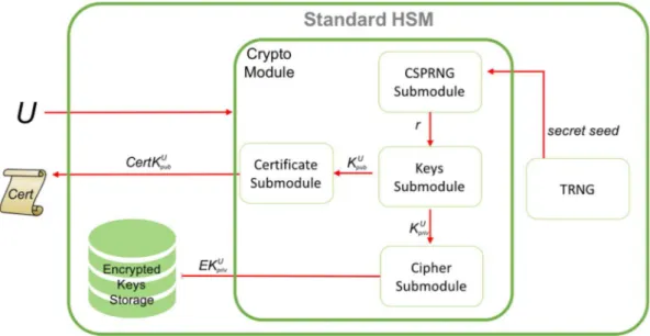
A typical key generation process in a HSM is described and summarized in the next figure:
Figure 1 - HSM keys generation process
Let U be the user. Through the API the HSM receives a request for key generation from a (legitimate) user U. In order to generate random values the TRNG provides a random seed for the CSPRNG. Then the CSPRNG generates a random value r. This random value is used to derive a pair of keys (KUpub; KUpriv).
The private key KUpriv will be stored in the stable storage of the HSM. Depending
on the level of security that the HSM has to guarantee the key can be encrypted before being stored. The public key KUpub, instead, is passed to the module for the
generation of the certificate which, in turn, is given back to the user, through the API.
Notice that the private keys stays in the HSM and is not given back to the user. The user can use the key only through the operations allowed by the API of the HSM.
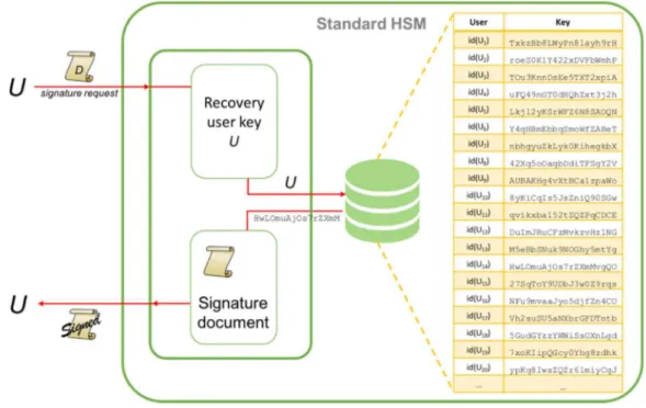
The next figure shows the process for signing a document through the HSM:
Figure 2 - HSM signature process
A legitimate user U requests the signature of a document D through the API. The HSM has to retrieve the private key KUpriv of user U by means of a search in the
embedded database. If the keys are encrypted the HSM needs to decrypt it. Then document D can be signed and the signed document is provided back to the user. Notice that the private KUpriv is never exposed outside the HSM.
Chapter 4
Enhanced
Hardware
Security
Module (EHSM)
4.1 On-the-fly key generation
In a real-world application of a HSM used by a certification authority (CA) to manage the cryptographic keys of the user and the documents signing process on behalf of the users, it is possible to identify two crucial points:
1 There are potentially many keys to manage (e.g. millions): it is necessary to store them and have backup copies;
2 The storage space can become a bottleneck: once all the available memory of the HSM has been used it is not possible to generate new keys.
The solution proposed in this thesis aims at avoiding these crucial points.
Without loss of generality it is possible to assume that for each user U there is a need to store a pair of keys (KUpub; KUpriv). Other types of keys (e.g. keys for
symmetric cryptography) can be handled in similar ways.
Recomputing the keys can be done exploiting the fundamental property of a CSPRNG: the sequence of pseudo-random numbers generated is a deterministic function of the seed. So it is possible to store only one seed, called master secret seed (mss), and from this seed it is possible to generate every time the same sequence of pseudo-random numbers. Let
Seq(mss) = r1, r2, …, rp where p is the period.
This sequence will be used to generate the needed keys on-the-fly. Of course it is necessary to make sure that:
1 The keys dynamically generated for user U are always the same;
2 The security warranties are the same as for the case when the keys are stored in the HSM.
To achieve property (1), to each user U of the system is associated an index
iU ∈ [1; p]
That is, to each user U is associated the pseudo-random value riU. When generating the pair of keys for user U first is retrieved riU from the CSPRNG; riU is uniquely determined by the user U, then it is used to generate (KUpub; KUpriv). Thus for
user U it will always be generated the same pair of public/private key.
Property (2) is achieved because the keys are not stored; thus information leakage can happen only if an attacker gets the master secret seed. The master secret seed is stored internally in the EHSM in lieu of the keys, so it is subject to the same protection as the keys in a HSM.
Normally the HSM stores for each user U its pair of private/public keys. Upon a user U request, the HSM retrieves (KUpub; KUpriv)and use them for the requested
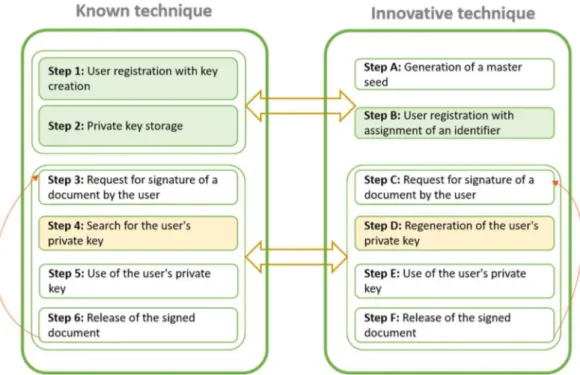
So on one extreme one has a HSM that stores all the keys, on the other extreme one has an EHSM that does not store any key but only the master secret seed (and each time a key is needed it gets generated). So the price to pay for not storing keys is the time needed to recompute the keys. Figure 3 compares the two approaches.
Figure 3 - Key generation process comparison
Between these two extremes it is possible to have approaches that store only some keys. The difference between the HSM and the EHSM is that in a standard HSM is used a database to store all the keys, while in an EHSM the key is on-the-fly regenerated upon every request.
4.1.1 Key generation
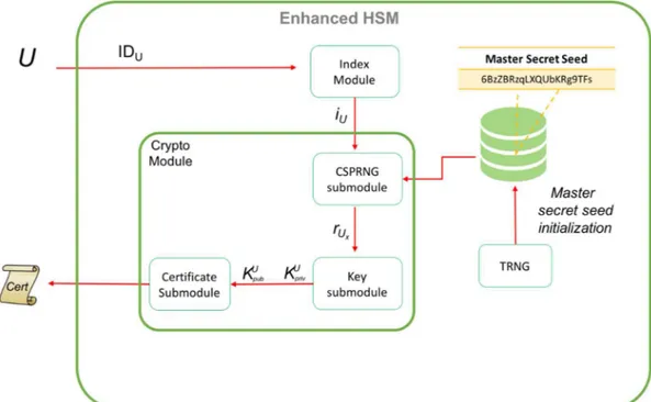
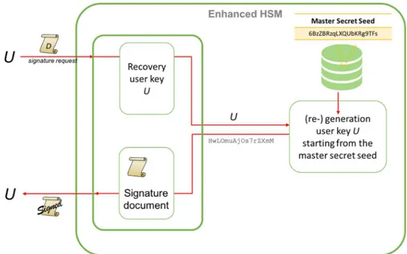
Figure 4 shows the detailed process of generating cryptographic keys in an EHSM.
Figure 4 - EHSM keys generation process
The database contains only the master secret seed mss. Let U be the user that requests the generation of the keys. If this is the first request, i.e., no mss has been generated yet, then a Random Module (TRNG) is used to generated the mss. An Index Module associates to each user U a unique index iU. Such a mapping can
be done in several ways and the specific method chosen is irrelevant (one could use a pre-determined mapping, like social security numbers or similar identification numbers): what it is needed is simply that each user gets a unique index (if a user is allowed to have multiple keys then an index is required for each key; in other words this means that the user needs to have a pseudonym for each key). Consider for example the case of Certification Authority (CA). The index iU can be assigned
upon a registration process: Ui are the clients that register to the service; the index
example, showing an official identification document. The index associated with the user is not an information to be kept secret with the same level of security as the private key. For this reason it is possible to manage these indexes outside the HSM. So the Index Module simple has to implement the mapping U -> iU. At this point
a CSPRNG is used to generate the pseudo-random sequence of numbers starting from the master secret seed and generating exactly iU numbers of the sequence.
The last generated number riU is then used to generate the pair of keys (KUpub;
KUpriv). At this point the EHSM proceeds with the response to the user to pass back
the certificate containing the public key. Notice that the private key is deleted.
4.1.2 Signing of a document
The following figure summarizes the process of signing a document in an EHSM.
Figure 5 - EHSM on the fly document signature
The user U provides the document D in the request. As for the key generation request, the EHSM uses the Index Module to retrieve the index iU associated to user
user has not yet generated the key an error must be raised; in the setting of EHSM a user does not really need to have a key generation phase but an enrollment phase which correspond to the fact that the user is given a unique index).
Once the private key KUpriv has been regenerated, the EHSM can sign the document
D and give back the signed document through the API. The private KUpriv (as well
as the public key KUpub) gets deleted.
The key point in an EHSM is the generation of the index iU of the pseudo random
number riu of the sequence.
In the following will be discussed an iterative approach through three different techniques and an approach based on random function.
4.2 Iterative approach
The first technique of the iterative approach simply iterates on the sequence of pseudo-random numbers generated by the CSPRNG starting from the master secret seed for iU times. The two alternative techniques, instead, store some of the values
of the pseudo-random sequence to speed up key generation.
Let U = {U1, U2, …, Un} be the set of users. The ordering used to denote this
set is not important in the sense that we do not have to use, and actually we don’t want to use, iU = j for the jth user.
Let I = {1, 2, …, Z} N be the set of possible indexes. As already mentioned above there could be several ways in which the mapping U -> I is constructed (iU can be assigned upon a registration process.). It is convenient to
keep Z as small as possible; clearly Z needs also to be large enough to deal with all possible users. In fact we can set I = N, and indicate with Z the biggest index used. This index will affect the performance of the system and it is convenient to keep it as small as possible. Notice that Z is tied to the period p of the CSPRNG. More precisely we must ensure that p > Z.
Having set the mapping U -> I we now concentrate on the mapping I -> R, where R is the set of pseudorandom numbers, that is on the mapping i -> ri.
4.2.1 Simple Iterative technique
The “simple iterative” technique is the most obvious one. To generate the ith
pseudorandom number of the sequence, it is possible to iterate on the sequence
r1, r2, …
starting from the first element r1 up to the ith one ri. This approach is very simple.
It requires exactly i iterations. This can be a problem if i is very large. This situation is actually what we expect since the main motivation for the use of an EHSM is the handling of a large number of keys, so large that we are worrying about space usage.
4.2.2 Linear Storing technique
An improvement over the “simple iterative” technique is a “linear storing” technique. In order to diminish the time needed for the simple iterative technique it is possible to store some keys in the database. Let s be a parameter (e.g., s = 1000). Upon first generation, now in the database are stored the pseudo-random values of the sequence with indexes that are a multiple of s:
rs, r2s, r3s ….
Thus, when the ith pseudo-random number of the sequence will have to be
generated, instead of iterating from r1, it is possible to start from ri/s.
Whit this method each request can be satisfied with at most s iterations. However it should be noticed that this comes at the expense of space: if s is too small the space-saving advantages of the EHSM are lost (in the extreme case of s = 1 we are back to a regular HSM).
4.2.3 Exponential Storing technique
A trade-off approach between the iterative and the linear storing one is an “exponential storing” technique in which instead of storing all values in the positions multiple of a constant s in the sequence, we store only the elements that are in the positions that are an exponent of a constant c.
Take for example c = 2, so the following sequence of values will be stored
r1, r2, r4, r8, r16, … r1024, …
This technique needs logarithmic space, thus still a substantial improvement over the linear space of a regular HSM. The time required to retrieve a pseudo-random value depends on the index: the smaller the index the fastest will be the retrieval. This is similar to what happens for the simple iterative technique but in this case do not have to start from the first element but only from the biggest power of c that is smaller than the index.
4.2.4 Time analysis
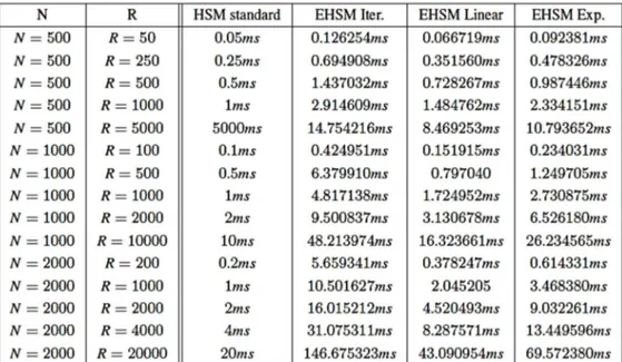
In order to assess the advantages and the disadvantages of the three proposed technique some preliminary tests have been conducted. The following table shows the advantages and the disadvantages of the proposed techniques. In the table is evaluated the extra time needed by an EHSM to satisfy a user request. More specifically N is the number of users and R is a sequence of user request. The sequence of requests is randomly generated. In these tests are shown the time needed to satisfy the request using a standard HSM and using an EHSM with each of the three proposed techniques. To simplify is assumed that a HSM database look-up takes 0.001ms; thus in a standard HSM a sequence of R user requests will take R × 0.001ms to be satisfied.
Table 1 reports the overall time consumption. The first variant is the one that takes more time since is the one that saves more space. Similarly the third variant takes more time than the second because it uses less space.
4.3 Random Function approach
The generation of the pseudo-random number riU can occur more efficiently,
without storing any information, apart from the initial seed (mss), through an alternative technique that makes use of the pseudo-random function. The proposed technique is independent from the specific pseudo-random function used, the choice of which will only influence the overall efficiency of the method. The fundamental property to satisfy is that starting from the user identifier IDU and
the associated index iU, the function always returns the same pseudo-random value
riU.
All pseudo-random functions satisfy this property. The method can be used both with the already known pseudo-random function and with any pseudo-random function that will be proposed in the future.
The advantages of the solution based on pseudo-random functions with respect to the iterative approach are the following:
1 It is necessary to store only the master secret seed, without the need to make intermediate values persistent through specific data structures;
2 All the values and information useful for creating the key pair for the user U with IDU (index iU, pseudo-random value riU ) are generated on-the-fly
starting from the master secret seed;
3 Reduced number of intermediate pseudo-random values to be generated before the specific pseudo-random value riU is given in output.
4.3.1 Example of implementation through “Goldreich, Goldwasser
and Micali pseudo-random function”
Below it is shown an example of riU generation through the use of the “Goldreich,
Goldwasser and Micali” (GGM) pseudo-random function. See [9] [10] and [13] for an in-depth description of how GGM is built. Very briefly for our purposes, at each step the GGM expands the input, with a specific binary length, in a pseudo-random sequence of double binary length.
This pseudo-random function is based on the Hash Tree data structure also known as Merkle Tree. A hash tree is a tree of hashes in which the leaves are hashes of data blocks and intermediate nodes in the tree are the hashes of their respective children.
In our application the hash tree is a complete balanced binary tree, where the values of leaves are the pseudo-random number riU to be calculated.
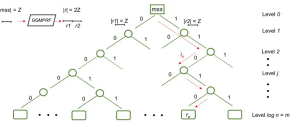
Figure 6 - Mapping of the user index iU with pseudo-random number riU
To generate the pseudo-random number riU for the user U it is necessary to expand
the master secret seed (mss) a number of times equal to the height of the binary tree that corresponds to the number of bits needed to represent the iU user index.
For example, if it is used the SHA-1 (Secure Hash Algorithm) to associate a unique index i to each user U the bit length of the index iU is equivalent to 160. If we
indicate this hash bit length with m, then all the possible hash values are n = 2m and corresponds to the set of the possible user indexes iU.
By assigning to each branch of the hash tree a binary value {0, 1}, the path from the root to a leaf is the binary representation of the user index iU. The initial input
of the Goldreich, Goldwasser and Micali pseudo-random function is the mss, the root of the binary tree.
At each step the function expands the input, with binary length z, in a sequence r of length |r| = 2z bits.
This sequence is splittet in two equal subsequences |r1| = z and |r2| = z and every subsequence is assigned to the children nodes of the current expanded node. In this way, to reconstruct the value of each father node, it is sufficient to concatenate the hash values of the two children nodes.
The number of times that the mss is expanded in a bits sequence with length 2z depends to the bit length of the iU user index and corresponds to the height of the
hash tree (m = logn levels).
The path from the root to the leaf represents the expansion path from the mss (root node) to the pseudo-random number (leaf node) riU, this binary path is described
through the binary representation of the user index iU.
Once the pseudo-random value riU has been calculated, it is possible to generate
cryptographic keys for the user U.
Using instead the pseudo-random function of “Noar and Reingold”, starting from the master secret seed the calculation is immediate and does not require any intermediate expansion.
SECTION 2
Outdoor Position
Certification Authority
Chapter 5
Global Navigation Satellites
System (GNSS)
5.1 Basic concepts
Before starting the description of the design of the OPCA, we will give some basic concepts concerning data and signals sent to earth by a GNSS satellite. Such knowledge will be useful later to understand the certification process. For simplicity we will limit the description to the signals and messages of the satellite navigation system more diffused globally: the NAVSTAR GPS of the United States. In order to provide the certification of the position an OPCA analyzes both high level data (GNSS messages of the specific satellite constellation properly encoded and modulated) and low-level data (raw data such as codes and characteristics of radio frequencies).
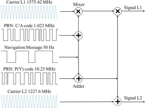
In particular the GPS simultaneously transmits several navigation messages using different Pseudo Random Number (PRN) ranging codes modulated on a specific radio frequency.
5.1.1 Ranging codes
Each satellite of the GPS constellation sends two types of legacy ranging codes, called C/A-code (Coarse Acquisition Code) and P(Y)-code (Precision Y-code). Both of these codes are pseudo-random binary sequences specific to each satellite. These codes are modulated on the same frequency through the Code Division Multiple Access technique. A fundamental characteristic of this code is the low probability of cross-correlation with the codes of th other satellites, with the background noise and other types of interference. Both codes are modulated on UHF radio frequency belonging to the microwave L band through the Bi-Phase Shift Keying. The C/A code is for civilian use and is transmitted in clear at repeated intervals on the L1 radio frequency.
Figure 7 - GPS ranging codes, navigation messages, carrier and signals
Although it is a PRN code, the C/A-code is predictable and reproducible from the mobile device to be synchronized with the code generated by the satellite. The P(Y)-
code is encrypted modulating an encoded sequence called W-code, periodically updated by the US Defense Department. The P(Y)-code is transmitted on the radio frequencies L1 and L2 and can be used for navigation exclusively for military purposes. This code in the common mobile devices for civil use cannot be used for navigation and positioning. It is not decipherable and not predictable, but given its structure and the known frequencies with which the W-code is applied, through appropriate techniques, it is possible to detect, trace and use it in conjunction with the C/A-code to improve positioning accuracy of the latter.
5.1.2 Navigation Messages
On the signals of the ranging codes C/A and P(Y) L1 is added a 50 bit/s navigation message. This navigation message includes 3 basic information:
date, time and health status of the specific satellite;
position in orbit of the single satellite of the constellation (ephemeris valid for 4 hours);
state of the constellation, approximate position of all satellites and ionospheric models for the correction of radio signal propagation errors (almanac - valid for 180 days).
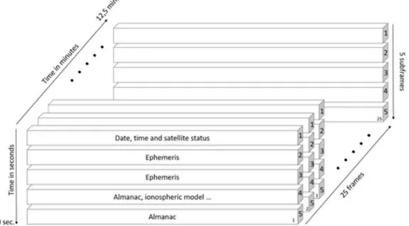
A GPS message consists of a 1500-bit frame. Each frame is composed of 5 subframes of 300 bits, numbered from 1 to 5, in turn composed of 10 words of 30 bits. Each word takes 6 seconds to be transmitted.
Figure 8 - GPS navigation messages: frame, subframes and words
Subframe 1 contains date and time, subframes 2 and 3 contain the ephemerides of the specific satellite, while subframes 4 and 5 contain the almanac (information on the whole constellation, ionospheric models, tropospheric models and other info). Each frame contains 1/25th of the entire almanac, this means that to transmit the entire almanac it takes 12.5 minutes.
5.1.3 Positioning
To accurately determine the position of a GNSS receiver on the Earth it is necessary to calculate the distance of at least 4 satellites. At any given moment, the more satellites are visible, the more accurate will be the calculation of the device's position.
Figure 9 - GNSS devices and satellites
Every navigation message contains the timestamp of when it was generated. This timestamp is produced through an atomic clock. Periodically, the satellite's time is synchronized from Earth to correct the errors induced by orbital velocity and Earth's gravity. From the propagation speed of the radio signal and the global ionospheric correction models contained in the GPS navigation message, it is possible to establish the distance from each satellite by calculating the propagation time of the signal; this can be done by comparing the starting timestamp generating on the satellite with the timestamp of arrival on the mobile device.
Chapter 6
OPCA design
6.1 Architecture
The data sent from GNSS are unreliable from a security point of view, because they can be easily forged by malicious attackers through specialized spoofing techniques. An OPCA is a certification authority whose purpose is to certify the position of a mobile device equipped with a GNSS (Global Navigation Satellite System) receiver. An OPCA defines a client/server architecture through which a user can certify his position by sending the geolocalization information needed to verify it to one or more remote servers. Once the truthfulness and reliability of the data received has been verified, the OPCA will issue and send to the client a signed positioning certificate with legal value certifying the position of the user in a given moment.
The proposed OPCA has a client-server architecture: there are one or more remote servers acting as trusted geolocalization authority (OPCAServer1, OPCAServer2, ...etc.) and a client running on the mobile device (OPCA-Client in short).
The OPCA authority operates in a specific geographical area, subdivided into different subareas, each of which operates a specific OPCAServer.
The particular geographical conformation of the area where the service is provided;
The number of potential users in the area;
The quality of the GNSS signal coverage.
Each OPCAServer offers a secure geolocalization service to users who request it through the OPCA-Client installed on the personal mobile device. This application has the task of collecting geolocalization information acquired through the GNSS receiver and sending it to the nearest OPCAServer, responsible for this subarea, using a secure communication protocol (e.g., SSL/TLS).
Figure 10 - OPCA architecture, area and subareas
Each OPCAServer is equipped with at least two GNSS receiving antennas, which allow to apply special antispoofing techniques based on radio interferometry analysis of the signals. The OPCAServer acquires GNSS signals at regular intervals within a reference time window whose width can be parameterized according to the load requirement. The acquired radio signals are processed, stored and divided into
high-level navigation data and low-level navigation data. Within each category the processed data have different priority and weight in the verification steps depending on the level of certification requested by the client.
6.1.1 Certification Levels
Safe positioning can be required for different types of services and/or scenarios. Each service can be associated with a particular level of certification corresponding to a specific level of security. For each level of certification, the client will be asked to send a particular data set. The highest level of certification (from the point of view of security) that a client can request depends directly on its ability to acquire and process the different types of high and low level data necessary for the appropriate verification steps. In case of insufficient information, the OPCA returns a probabilistic answer on the degree of reliability of the client request. In some usage scenarios it may be sufficient to know that geolocalization is not certain, but the checks carried out indicate that it would be difficult to recreate an eventual spoofing attack; anyway, the attack would require huge and sophisticated technological resources. Therefore the OPCA can catalog the client requests with respect to the degree of reliability of the information received and consequently re- lease different certification security levels of the position according to the specific scenario and/or service requested.
6.1.2 Scalability: OPCA area and subareas
To increase efficiency, scalability and security of the service it is possible to provide a balancing and proximity mechanism of requests through the installation of multiple servers and GNSS receivers within the same subarea. In relation to the specific needs of the case (size of the subarea, number of requests, particular geographic configuration) the communication between the various OPCA servers belonging to the same subarea may include a peer-to-peer or a master-slave configuration using secure communication protocols.
6.1.3 OPCA Client requirements
To avoid tampering of the OPCAClient app, it is essential to execute the client app in a safe execution environment (Sandbox). An example of sandbox is the “Samsung KNOX System" designed for Android operating systems; other Android sandbox systems are described in [23].
In addition to the data contained in high-level navigation messages, the application must be able to access and manipulate low level raw data (for different certification levels) of the radio signals detected by the GNSS receiver through appropriate services provided by the hardware and/or by the software. For example the latest versions of the Android OS provides an application programming interface for accessing low-level features of a GNSS signal.
The user must be registered to the secure geolocalization service, identifying both the instance of the client application installed on the mobile device and the device itself (enrollment phase). It is necessary to ensure a unique association “user-application-device".
The mobile device must have the GNSS sensor switched on during the user registration/enrollment phase and during the position's certification request. For the success of the position's certification process it is essential to synchronize the clock of the client device with the clock of the server through a time synchronization protocol.
6.1.4 GNSS high level and raw data
To apply different antispoofing techniques and certify the relative level of secure positioning, the OPCAServer requests the OPCAClient to send the high and low (raw) level data shown in Tables 1 and Table 2. For simplicity of exposure, we will refer exclusively to some high level and raw data of the GPS satellite navigation system. Upon reception of the data from the client side, the OPCAServer will start the analysis and the comparison with the GNSS data acquired on the server side in the reference time window. The analysis process involves several steps in which specific checks will be carried out for each type of information.
GPS High Level Data
Description Data
GPS data frame structure (subframes and telemetries words)
Preamble Parity bits
Synchronization bits
GPS data frame's navigation message (words)
Correction on standard frequencies
Age of data (AODC) and coe_cients for the ionospheric delay related to the L1 frequency sent by the control center
Ephemeris of each satellite and AODE instant reference (Age
of Data) sent by the control center;
Almanac of the whole satellite constellation generated by the control center (truncated ephemerides, clocks corrections,
satellite identi_cation number, satellite health status)
High-level data processed by the GPS satellite receiver
Total number of in sight satellites Total number of in use satellites PRN Number of the satellite
Elevation in degrees (max 90) of the satellite Azimuth in degrees (from 000 to 359) of the satellite
Eccentricity
Satellite speed with respect to the ground HDOP (Horizontal Dilution of Precision)
VDOP (Vertical Dilution of Precision) PDOP (Position (3D) Dilution Of Precision TDOP (Time Dilution Of Precision) Date and time
Week number of the GPS system Latitude of the calculated position Longitude of the calculated position Receiver height above sea level Separation from the Geoide GPS signal quality
Magnetic variation
High-level data processed by the satellite receiver related to other satellite
navigation constellations (GLONASS, GALILEO, BEIDU ... etc.)
GPS Raw Data
Description Data
Predictable pseudorange code GPS C/A-code L1
Code values Code phase values
GPS radio signals Carrier values
Phase values
Doppler shift values
Signal strength values
C/N0 carrier to noise density e/o SNR signal to noise ratio
Noise code statistics of the GPS pseudorange C/A-code L1
Standard deviation of the semi-major axis of the error ellipse (in meters)
Standard deviation of the semi-minor axis of the error ellipse (in meters);
Orientation of the semi-major axis of the ellipse of error (in degrees)
Standard deviation in meters of the latitude error
Standard deviation in meters of longitude error
Standard deviation in meters of altitude error
Values related to the pseudo-random pattern of the encrypted military code P (Y)-Code not predictable
6.2 Server side verification steps
The verification of the information of positioning is organized in 4 steps, which reflect the most secure GNSS antispoofing techniques. Such steps are organized in security, reliability and complexity order.
6.2.1 Step A - Check of signals direction, speed and movement
This set of checks include check of signals direction, speed and movement of the received GPS satellites. This is the most complex verification phase in terms of hardware and software resources and corresponds to the highest level of the position's certification. For every GPS satellite for which data is received, the OPCAServer acquires the values (a1) and the phase (a2) of the PRN C/A-code L1, the values of the carrier (a3) and the phase (a4) of the low level radio signal and the values of the doppler shift (a5) produced by the relative movement satellite-receiver (continuous change of the signal frequency).
Using multiple GNSS antennas installed in the subarea where the specific OPCAServer operates, appropriate interferometry techniques are used to calculate the direction of the radio signals and speed of the satellites, in the specific window of reference, with respect to the server. The same values (a1, a2, a3, a4, a5) are also acquired on the client side (OPCAClient) and sent to the OPCAServer for the calculation of the direction of the signals and the speed of the satellites with respect to the client. Discrepancies and incompatibilities between signal direction and satellite speed calculated in the reference window between OPCAServer and OPCAClient application indicate that, with high probability, the signal has been forged.
6.2.2 Step B - Check signal power, signal/noise ratio and pseudorange
code noise
This set of checks include check of the power, the signal/noise ratio of the radio signal and the noise of the pseudorange code C/A-code L1 of the GPS.
In this phase, it is verified that some intrinsic characteristics of the GNSS radio signals acquired on the client side, in the reference time window, are plausible and not artificially generated. The OPCAServer verifies that the values sent by the client relative to the signal power (b1), to the signal/noise ratio (b2) - (C/N0 - carrier to noise density and/or SNR - signal to noise ratio) - and to the noise of the pseudorange code C/A-code L1 (b3) belong to a certain range of values that can be recorded by a real mobile device.
6.2.3 Step C - Check military pseudorange code pattern
This set of checks include check of the pattern of the encrypted GPS military pseudorange code P(Y)-code L1. In this phase, the OPCAServer traces the pattern of the military pseudorange code P(Y)-code L1 (c3) encrypted and not predictable for each GPS satellite received within the reference time window. The values of these patterns acquired on the server side will be compared with the values of the patterns acquired and sent on the client side. These patterns of values must be compatible.
6.2.4 Step D - Check GPS data frame structure
This set of checks include check of the GPS data frame structure, of the data bits contained in it (telemetry, navigation message) and of the high level data processed by the GNSS client receiver related to GPS and all other satellite navigation constellations (GLONASS, GALILEO , BEIDU, etc.).
In this step the OPCAServer compares its acquired values to data frame structure (d1), navigation messages (d2) (data bit contained in the data frame) and high-level data with those processed and sent by the client (d3) of all the satellites captured in the reference time window. The client values must be identical to the corresponding values acquired on the server side.
6.3 Certification levels
The maximum reliability and level of the position's certification is obtained by processing the checks in all four verification steps.
There are two main levels of certification: Level A and Level B. Each level of certification of the position can be used by the user in the process of requesting a specific service provided by a subject/company/institution operating in a particular context/scenario/sector of business.
Level A is the highest in terms reliability and can be used in mission-critical contexts, where the requirements in terms of security in position detection are stringent. This level is divided into three certification sub-levels: Level A1, Level A2 and Level A3.
For the release of the highest position's certification level (Level A1), the OPCAServer must be able to perform the checks of all four verification steps through the information acquired and processed on the server side and sent by the client: verification of low level data (steps A, B and C) and verification of high level data (step D).
The release of Level A certification requires higher costs in terms of money on the client side given the greater need of resources in terms of computational power on the server side (hardware/software resources, memory, disk space and computational time).
Level B corresponds to a certification level of the position with a lower reliability and safety index. This level can be used in non-mission critical contexts.
To release this certification level, only high-level GNSS data are verified (step D) with a low need in terms of computational resources on the server side.
Following Table 3 summarize the steps required by each certification level:
Completed Steps A-B-C-D B-C-D C-D D Certification Level A1 A2 A3 B
Each of these levels assumes that the OPCAClient is able to acquire, process and send the relevant information necessary to perform the checks required in the specific steps. For example, in steps A, B and C the OPCAClient must be able to acquire and process the raw data of the GNSS signals made available by the underlying hardware/software platform of the mobile device. In the case of lack of particular information, the relative verification step will not be completed, but will be released the certification level closer to the client's request, based on the availability of the data sent by the client.
The following flowchart summarizes the different verification steps performed by the OPCAServer regarding a Level A1 certification request.
Chapter 7
Spoofing and countermeasures
7.1 GPS spoofing and countermeasures
The main purpose of the OPCAServer is to detect and contrast all those situations in which an attacker (directly or indirectly) wants to exhibit a position different from the one actually occupied.
The spoofing techniques have the objective to reproduce a GNSS radio signal as faithful as possible (carrier, frequency, phase, doppler shift, signal power, signal to noise ratio), through which to send to the mobile device a PRN ranging code (data bit) that encodes a fake navigation message (data frame) appropriately modified or created ad hoc, such as to induce the mobile device to calculate a different position from that currently occupied.
At this point we are remark that, in theory, it is possible to carry out spoofing techniques through several attackers located in different geographical areas. A typical case is that of an attacker who wants to exhibit a position different from that really occupied through the help of an accomplice who is really in the fake position to want to exhibit. In this specific case the accomplice could acquire the real signal through his device and send to the attacker the geolocation data necessary to carry out the attack. Although difficult to apply, due to the need of at least one accomplice
who actually occupies the fake position in the specific instant of time, one must be aware that it is not possible to exclude such a type of attack a priori. In the following thesis work are investigated only the spoofing techniques and the possible countermeasures involving a single attacker. Scenarios involving more attackers distributed in different geographical areas are left as future research work.
In the specific case of GPS, a well-made simulator should be able to reproduce the following signals, PRN codes and navigation messages:
1 The predictable civil PRN code C/A-Code L1 through which to send to the client the structure and the navigation message (frames, subframes and words) of the specific GPS satellite;
2 The signal pattern of the encrypted military PRN code P(Y)-code, referred to the specific satellite and to the specific time window in which the position certification request occurs, and detectable by some GNSS receiver as a kind of background noise.
As regards point 1, it is easy to reproduce the high-level navigation message even through cheap and widespread GNSS hardware or software simulators.
Point 2 is much more complicated to emulate because it is a military code that cannot be decrypted by a common civil GNSS devices and/or a simulator. Independently of the required certification level, the OPCAServer will always check the high-level data (step D - data frame and navigation message) acquired and processed on the server side in the reference time window, comparing them with those processed and sent on the client side.
As the required certification level increases, further checks on low-level data will be added (step A - signal direction and satellite speed, step B – signal strength and signal to noise ratio, step C - military code pattern).
The most widespread spoofing scenarios of a GNSS signals with a single attacker in the scientific literature are basically three. Some of these are purely theoretical attacks, because in practice they require considerable resources in terms of instrumentation, time and computational capacity.
7.1.1 Spoofing with a single antenna and a GNSS simulator in a
protected environment
The most complex and sophisticated scenario to contrast is that in which a user wants to falsify his position by isolating the mobile device from real signals coming from the space and radiating it with different fake signals created ad hoc using dedicated antennas and GNSS simulators.
In reality every single GPS satellite moves in space with a speed close to 14,000 km per hour. It is important to note that signals from different satellites come from space to the GPS receiver with different angles.
Figure 12 - Spoofing of the GNSS signals with a single antenna and a GNSS simulator in a protected environment
In theory, therefore, a simulator in a protected environment, in order to recreate the portion of GPS satellite constellation detectable in a given place and moment, should reproduce for each visible satellite the specific predictable PRN code C/A-Code L1 (low level signal) and the specific navigation message (high level data) through a dedicated simulator. Moreover, these simulators should be positioned coherently with the real position in the sky of the corresponding satellite to be simulated and should reproduce both the movement of the specific satellite and the Doppler shift (displacement) of each single radio signal.