UNIVERSITÀ DEGLI STUDI DI ROMA
"TOR VERGATA"
FACOLTA' DI INGEGNERIA DELLE TELECOMUNICAZIONI
DOTTORATO DI RICERCA IN INGEGNERIA DELLE
TELECOMUNICAZIONI E MICROELETTRONICA
CICLO XXI
MOBILITY MANAGEMENT IN NEXT
GENERATION NETWORKS
Andrea Polidoro
A.A. 2008/2009
Docente Guida/Tutor: Prof. Stefano Salsano
Coordinatore: Prof. Giuseppe Bianchi
Ad Alessandra, a nostro figlio (ancora nella sua pancia) e alla nostra futura famiglia
Abstract (English)
The ITU-T definition of Next Generation Networks includes the ability to make use of multiple broadband transport technologies and to support generalized mobility. Next Generation Networks will need to integrate several IP-based access technologies in a seamless way. In this Thesis, we first describe the requirements of a Mobility Management scheme for multimedia real-time communication services; then, we report a survey of the Mobility Management schemes proposed in the recent literature to perform vertical handovers between heterogeneous networks. Based on this analysis, we propose an application-layer solution for Mobility Management called MMUSE (Mobility Management Using SIP Extension), which is based on the SIP protocol, and satisfies the most important requirements demanded for a proper implementation of vertical handovers. We also implemented our proposed solution, testing it on the field and proving its overall feasibility and its interoperability with different terminals and SIP servers.
In our work we also report measurements results which analyze the performance of the solution in a real world environment, using commercial access networks (WiFi, 3G)
Finally we discuss a methodology for performance evaluation of the solutions for vertical handovers previously described. The performance evaluation is based on simple analytical models and covers both the ideal case (no packet loss) and the real case where there is a given packet loss rate. The methodology is applied to a comparison among three solutions, namely MIPv4, classical SIP mobility management using re-INVITE messages and the proposed MMUSE SIP based solution.
Abstract (Italiano)
La definizione che l’ITU-T fornisce delle “Next Generation Network” (NGN) include la possibilità di poter utilizzare differenti tecnologie di accessi a banda larga e di supportare la mobilità. Inoltre le reti NGN hanno la necessità di integrare le diverse tecnologie di accesso alla rete IP in maniera del tutto trasparente. In questa tesi dapprima si definiscono i requisiti che una soluzione per la gestione della mobilità nei sistemi di comunicazione real-time dovrebbe avere. Successivamente si analizzano le soluzioni per la gestione della mobilità
presenti in letteratura. A partire da quest’analisi nasce MMUSE (Mobility Management Using Extension) una soluzione per la gestione della mobilità a livello applicativo basata sul protocollo SIP in grado di soddisfare la maggior parte dei requisiti richiesti ad un sistema di gestione della mobilità fra reti eterogenee. Tale soluzione è stata inoltre implementata, per testare sul campo le sue capacità e la sua interoperabilità con diversi terminali e Server SIP.
Inoltre, al fine di valutarne le prestazioni è stata effettuata una campagna di misure nel mondo reale utilizzando alcune reti di accesso commerciali (sia 3G che WiFi).
Infine, si propone una metodologia per la valutazione delle prestazioni delle differenti soluzioni di gestione della mobilità precedentemente illustrate. Tale metodologia si compone di un semplice modello analitico applicabile sia ad un caso ideale (senza perdite) che un caso reale con un predefinito tasso di perdita dei pacchetti. Il modello è stato applicato a tre soluzioni MMUSE, MIPv4 e SIP re-INVITE.
Acknowledgements
Sebbene tutta la tesi sia scritta in inglese, preferisco ringraziare le persone che mi hanno accompagnato in questi anni di dottorato nella mia lingua madre, l’italiano in quanto è la lingua con cui meglio riesco ad esprimere i miei sentimenti.
Non posso non partire con ringraziare la persona che mi ha introdotto in quel bellissimo mondo che è la ricerca universitaria ovvero il mio tutor e amico Stefano Salsano. Ricordo ancora il giorno in cui dopo timido e impacciato mi recai nel suo ufficio per chiedere la tesi, ma ricordo ancora meglio il giorno in cui lui mi propinò la possibilità di fare il dottorato. Accettai di getto e anche se da poco ho rinunciato alla ricerca, sono ancora convinto di aver fatto la scelta giusta.
Grazie Stefano, grazie per l’opportunità, grazie per esserci sempre stato disponibile per me nonostante i tuoi mille impegni giornalieri, per avermi fatto crescere professionalmente e per avermi, come hai detto tu stesso al piccolo Matteo “reso bravo”.
Un grande grazie lo devo anche Gianluca Martiniello e a Luca Veltri che con Stefano hanno dato inizio a quello che poi è diventata la mia tesi di dottorato. Ho avuto l’occasione di lavorare con Gianluca solo un paio di mesi, e il mio rammarico è che sono stati troppo pochi. A Luca devo circa un milione e mezzo di consulenze telefoniche e via mail, è buffo pensare al fatto che ho avuto l’opportunità di scrivere molti articoli con lui, di contribuire alla mitica libreria mjsip ma che, di fatto, l’ho visto di persona una sola volta.
E come non ringraziare tutto il netgroup, questo stupendo gruppo di lavoro creato da Stefano, dal Prof. Blefari e dal Prof. Bianchi e che è stato il mio ambiente di lavoro in questi anni. Come dimenticarsi di tutti gli amici cui ho chiesto consulenze di inglese in cambio di consulenze su office, come dimenticare tutti i sorrisi di questi anni con Francesca Lo Piccolo, Dario, Lorenzo, Alessandro, Giovanni, Saverio, Arianna, Simone, Francesca Martire, Vito, Vincenzo, Mimmo. Grazie a tutti per aver arricchito scientificamente ed umanamente la mia vita.
Un grande grazie anche a Fabio Ricciato e Peter Reichl che hanno reso possibile il mio internship in FTW e grazie ad Alessandro, Marina, Danilo e Sabine per la loro squisita ospitalità e amicizia.
Infine un grazie particolare a quella che lo scorso giugno è diventata mia moglie Alessandra. Grazie per aver colmato la mia vita con la tua presenza e per essere sempre stata
al mio fianco in ogni circostanza. Grazie per aver accettato con serenità alcune scelte difficili. Ma soprattutto grazie per il figlio che porti in grembo, che renderà ancora più viva la nostra famiglia. E grazie anche a te piccoletto, grazie perché il tuo arrivo mi sta donando emozioni nuove, nuove consapevolezze e nuove sfide. Spero tanto di essere un buon padre per te e spero che tu, nella vita che ti accingi ad affrontare, possa incontrare persone stupende come quelle che sto ringraziando in questa pagina.
Contents
ABSTRACT (ENGLISH) 3
ABSTRACT (ITALIANO) 3
ACKNOWLEDGEMENTS 5
INTRODUCTION 1
1 HANDOVER SOLUTIONS OVERVIEW 2
1.1 REFERENCE SCENARIO AND REQUIREMENTS 2
1.2 SOLUTIONS FOR MOBILITY MANAGEMENT 4
1.2.1 LINK LAYER 4
1.2.2 NETWORK LAYER 7
1.2.3 TRANSPORT LAYER 8
1.2.4 APPLICATION LAYER 10
2 MMUSE: MOBILITY MANAGEMENT USING SIP EXTENSIONS 12
2.1 MMUSE OVERVIEW 12
2.2 MMUSEARCHITECTURE 17
2.2.1 THE MOBILITY MANAGEMENT CLIENT 17
2.2.2 THE MOBILITY MANAGEMENT SERVER 18
2.3 MMUSE SIGNALING ASPECTS 20
2.3.1 ROLE OF THE SESSION BORDER CONTROLLER 20
2.3.2 CHOICE OF SIP MESSAGES FOR MOBILITY MANAGEMENT 21 2.3.3 CHOICE OF TERMINAL IDENTIFIERS FOR SIP MOBILITY MANAGEMENT PROCEDURE 21
2.3.4 ROUTING OF REQUESTS AND RESPONSES 22
2.4 MMUSE:SIPPROCEDURES 24
2.4.1 LOCATION UPDATE REGISTRATION: INITIAL AND “OFF-CALL” MOBILITY MANAGEMENT 25
2.4.2 USER REGISTRATION 27
2.4.3 SESSION ESTABLISHMENT 32
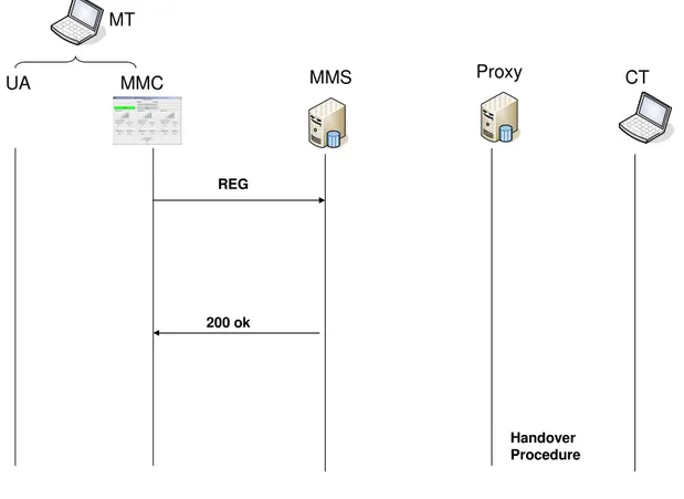
2.4.4 ON-CALL MOBILITY: THE HANDOVER PROCEDURE 44
2.5 HANDOVER CRITERIA 47
2.5.1 QUALITY OF SIGNAL 47
2.5.2 QUALITY OF LINK 47
2.5.3 LOCATION-ASSISTED 55
2.6 MMUSEIMPLEMENTATIONS AND TESTBED 58
3 EVALUATION OF MMUSE 60
3.1 MMUSE:HANDOVER PERFORMANCE 60
3.1.1 EVALUATION OF ACCESS NETWORK PERFORMANCE 62
3.2 MATCHING CRITERIA 69 3.3 MMUSE VS.OTHER SOLUTIONS:PERFORMANCE EVALUATION 70
3.3.1 METHODOLOGY FOR PERFORMANCE EVALUATION 70
3.3.2 MOBILITY MANAGEMENT MECHANISMS 73
3.3.3 EVALUATED SCENARIOS 73
3.3.4 HANDOVER PERFORMANCE EVALUATION (NO FAILURE CASE) 76 3.3.5 HANDOVER PERFORMANCE EVALUATION:FAILURE CASE 80
4 MMUSE IMPROVEMENTS 86
4.1 OVERVIEW OF THE PROPOSED SOLUTION 87
4.1.1 ARCHITECTURE 87 4.1.2 MMS CHANGE CRITERIA 90 4.1.3 SIGNALING REQUIREMENT 90 4.2 SIGNALING PROCEDURES 91 4.2.1 LOCATION UPDATE 91 4.2.2 MMS CHANGE 93 CONCLUSIONS 98 REFERENCES 100
APPENDIX A: REPORT OF MMUSE MEASUREMENTS 103
1 ACCESS NETWORK PERFORMANCE EVALUATION 103
2 EVALUATION OF HANDOVER PERFORMANCE 105
2.1 HANDOVER3G(NET2)–WIFICAMPUSNETWORK 105
2.1.1 1^ MEASURE:2006-05-20,10.32 AM 105
2.1.2 2^ MEASURE:2006-05-20,11.35AM 106
2.1.3 3^ MEASURE:2006-05-20,12.35 AM 107
2.2 HANDOVERWIFICAMPUSNETWORK–3G(NET2) 108
2.2.1 1^ MEASURE:2006-05-20,10.45 AM 108
2.2.2 2^ MEASURE:2006-05-20,11.47AM 109
2.2.3 3^ MEASURE:2006-05-20,12.50AM 110
2.3 HANDOVER3G(NET 1)–WIFICAMPUSNETWORK 111
2.3.1 1^ MEASURE:2006-05-21,2.02 PM 111
2.3.2 2^ MEASURE:2006-05-21,3.25 PM 112
2.4 HANDOVERWIFICAMPUSNETWORK–3G(NET1) 113
2.4.1 1^ MEASURE:2006-05-21,2.30 PM 113
2.4.2 2^ MEASURE:2006-05-21,4.00 PM 114
2.5 HANDOVER3G(NET2)-BLUETOOTH NETWORK 115
2.5.1 1^ MEASURE:2006-05-18,4.00 PM 115
2.5.2 2^ MEASURE:2006-05-18,5.00 PM 116
2.6 HANDOVERBLUETOOTHNETWORK–3G(NET2) 117
2.6.1 1^MEASURE:2006-10-20,12.00 AM 117
3 EVALUATION OF RTT IN HANDOVER PROCEDURE 119
3.1 HANDOVERWIFICAMPUSNETWORK–3G(NET1) 119
3.1.1 1^ MEASURE:2006-05-21,2.30 PM 119
3.2 HANDOVERWIFICAMPUSNETWORK–3G(NET2) 119
3.2.1 3^ MEASURE:2006-05-20,12.50AM 119
3.3 HANDOVERBLUETOOTHNETWORK–3G(NET2) 120
Mobility Management in Next Generation Networks
Introduction
Nowadays, the range of available wireless access network technologies includes cellular or wide-area wireless systems, such as cellular networks (GSM/GPRS/UMTS) or WiMax and local area or personal area wireless systems, comprising for example WLAN (802.11 a/b/g) and Bluetooth. A great part of today's mobile terminals are already capable of having more than one interface active at the same time. In addition, the heterogeneity of access technologies will likely increase in the future, making the seamless integration of the different ways in which a user can access the network a key challenge for Next Generation Networks. Services need to be provided to the user regardless of the particular access technology used, and IP protocol will be the common language for this integration at the network level.
The choice of the network interface to be used at a given time can be based on economical or performance considerations, anyway it is desirable that the user perceives the service in a seamless way, notwithstanding the changes of access interface (and technology). It is not easy to fulfill this requirement as moving across different access technologies may imply changes in the parameters of the communication, e.g., the IP address. The research community has given several answers to these needs, proposing different Mobility Management approaches, which can be classified according to the layer at which they operate. A first option is to work at the network layer, as Mobile IP does. Alternative approaches provide seamless service fruition by operating at the application layer; among them, a favorite choice is to rely on the SIP protocol for signaling purposes. Following this approach, in this thesis we propose a SIP-based solution that supports vertical handovers without disruption of real-time multimedia communication services. The solution is called “Mobility Management Using Sip Extension” (MMUSE).
This Thesis is organized as follows. In chapter 1 we introduce the reference scenario and an overview of the most important mobility solutions in literature. MMUSE, our solution is shown in chapter 2 introducing its main concepts and analyzing the details of the signaling procedures and handover policy. Chapter 2.6 analyzes MMUSE’s performance evaluation with respect to other handover solutions in literature. Finally chapter 4 shows a solution that improves the MMUSE architecture scalability.
1
Handover solutions overview
1.1
Reference Scenario and Requirements
Figure 1.1 shows a Mobile Terminal (MT) that can connect to different Access Networks (ANs) (AN1, AN2 and AN3). The different ANs could be based on different wireless or wired technologies (e.g. Wi-Fi, Bluetooth, GPRS/EDGE, 3G/HDSPA, WiMax, fixed Ethernet); the MT could be connected to more than one access network at the same time, if it has more than one physical network interface. Note that the ANs can provide public or private IP addresses to the MT (in most typical scenarios the Access Networks are likely to provide private IP addresses). For example, in Figure 1.1 AN1 and AN3 provide a private address (as shown by the NAT box), while AN2 provides a public address. The MT needs to be reachable in order to receive incoming calls on whatever network it is roaming. The MT wants to communicate with a “Correspondent Terminal” (CT), which can have a public address (like CT2 in the figure) or a private IP address (like CT1 in the figure). When a communication session is active, the MT may need to change the AN, as the interface that is using may become not available due to loss of signal, or it could suffer of a high packet loss or packet delay.
Mobile Terminal (MT) AN1 AN2 AN3 CT1 CT2 Public Internet Proxy/Registrar of CT Proxy/Registrar of MT NAT NAT NAT
Figure 1.1: Reference Scenario
Our analysis focuses on “vertical” handover, between heterogeneous networks; the “intra-technology” and “intra-network” handovers are out of the scope of our activity. For
example, a MT connected to a cellular network may perform several handovers among different cells within the cellular network, but it will remain attached to the same AN, with reference to the scenario of Figure 1.1. “Vertical” handovers are defined as the switch between two different access technologies or the switch between two different access networks operating with the same technology, if the IP address provided to the MT changes as a consequence of the handover.
The focus of this thesis is only on Mobility Management for real time services that use UDP as transport protocol: Mobility Management and seamless handover for services that use TCP transport is out of our scope.
The Mobility Management procedures basically consist in:
- allowing users to be reached on whatever access network they are;
- allowing the “handover” of active real-time communication session from an access network to another one.
Hereafter we identify the requirements of an “optimal” Mobility Management solution: 1) The vertical handover must be as fast as possible. This means that the user should not
perceive any service interruption. If it is not possible to completely hide the effect of the handover, then the service disruption should be minimized.
2) When switching from an access network to another, the Mobility Management signaling should be sent over the new target network, since the old one could suddenly become unavailable; in such a case it is necessary to perform the whole handover procedure on the new network (this is known as “Forward” handover). On the contrary, if the old network is still available, the availability of both networks can be exploited in order to assist and speed up the whole procedure.
3) The Mobility Management solution should be compatible with NAT traversal. Users should be able to roam from an access network to another, even when one or both access networks use private IP addressing and lie behind a NAT.
4) The Mobility Management solution should not require modifications to the CTs. All existing terminals should be able to interoperate with roaming MTs.
5) Existing User Agents (UAs) in the MT should not be modified in order to be able to exploit the roaming capability provided by the Mobility Management solution.
6) The Mobility Management solution should not require additional support in the access networks. The access networks are only required to provide IP connectivity.
7) The capability to offer Mobility Management services should not be an exclusive prerogative of the network operators.
8) The actual location and the movements of the user should not be visible from the CT, in order to preserve the privacy of the users.
9) The Mobility Management solution should properly interact with the User Registration procedures and with existing solutions for handling Personal Mobility (for example these solutions allow a user to use a set of mobile and fixed terminals in parallel or in sequence, as he desires). In other words, the Mobility Management solution should be able to complement current services offered by existing SIP proxy/registrar servers, without the need of redesigning the service logic or modifying the SIP protocol implementation in these servers.
1.2
Solutions for Mobility Management
Focusing on IP based devices and services, these requirements for mobility management solutions can be tackled at various levels of the protocol stack from application level (e.g. SIP based solutions) to network level (e.g. Mobile IPv4, Mobile IPv6) to link layer level (e.g. 802.21). A large number of different mobility management solutions operating at these different levels have been proposed so far, both in the literature and in the standard bodies.
This section shows a summary of these mobility solutions.
1.2.1 Link Layer
1.2.1.1
802.21
802.21 [10] is a standard defined by the IEEE in order to optimize handovers among heterogeneous IEEE 802 networks and to facilitate handovers between IEEE 802 networks and cellular networks.
This standard provides link layer intelligence and other related network information to upper layers to optimize handovers between heterogeneous networks. This includes media types specified by Third Generation (3G) Partnership Project (3GPP), 3G Partnership Project 2 (3GPP2), and both wired and wireless media in the IEEE 802 family of standards. In this standard, unless otherwise noted, media refers to method/mode of accessing a
telecommunication system (e.g., cable, radio, satellite), as opposed to sensory aspects of communication (e.g., audio, video).
The purpose of this standard is to enhance the experience of mobile users by facilitating handovers between heterogeneous networks.
This standard supports cooperative use of information available at the mobile node and within the network infrastructure. The mobile node is well-placed to detect available networks. The network infrastructure is well-suited to store overall network information, such as neighborhood cell lists, location of mobile nodes, and higher layer service availability. Both the mobile node and the network make decisions about connectivity. In general, both the mobile node and the network points of attachment (such as base stations and access points) can be multi-modal (i.e., capable of supporting multiple radio standards and simultaneously supporting connections on more than one radio interface).
The overall network can include a mixture of cells of drastically different sizes, such as those from IEEE 802.15, IEEE 802.11, IEEE 802.16, 3GPP, and 3GPP2, with overlapping coverage. The handover process can be initiated by measurement reports and triggers supplied by the link layers on the mobile node. The measurement reports can include metrics such as signal quality, synchronization time differences, and transmission error rates. Specifically the standard consists of the following elements:
a) A framework that enables service continuity while a mobile node (MN) transitions between heterogeneous link-layer technologies. The framework relies on the presence of a mobility management protocol stack within the network elements that support the handover. The framework presents media independent handover (MIH) reference models for different link layer technologies.
b) A set of handover-enabling functions within the protocol stacks of the network elements and a new entity created therein called the MIH Function (MIHF).
c) A media independent handover Service Access Point (called the MIH_SAP) and associated primitives are defined to provide MIH Users with access to the services of the MIHF. The MIHF provides the following services:
i. The Media Independent Event service that detects changes in link layer properties and initiates appropriate events (triggers) from both local and remote interfaces.
ii. The Media Independent Command service provides a set of commands for the MIH Users to control link properties that are relevant to handover and switch between links if required.
iii. The Media Independent Information service provides the information about different networks and their services thus enabling more effective handover decision to be made across heterogeneous networks.
iv. The definition of new link layer service access points (SAPs) and associated primitives for each link-layer technology. The new primitives help the MIHF collect link information and control link behavior during handovers. If applicable, the new SAPs are recommended as amendments to the standards for the respective link-layer technology
Figure 1.2: MIH services and their initiation
Figure 1.2 shows the placement of the MIHF within the protocol stack of a multiple interfaced MN or network entity. The MIHF provides services to the MIH Users through a single media independent interface (the MIH service access point) and obtains services from the lower layers through a variety of media dependent interfaces (media-specific SAPs).
1.2.2 Network Layer
1.2.2.1
Mobile IP
Mobile IP (MIP) [9] is a mobility solution working at the network layer. IPv4 assumes that every node has its own IP address, which should remain unchanged during a communication session. MIP introduces the concepts of Home Address (the permanent address of the MT) and of Care-of-Address (CoA). The latter is a temporary address assigned to the MT as soon as it moves from its home network to a foreign one. A specific router in the home network (Home Agent) is informed as soon as the node acquires the CoA in the foreign network (from a so-called Foreign Agent). The Home Agent acts as an anchor point, relaying the packets addressed to the Home Address towards the actual location of the MT, at the Care-of-Address.
Using Mobile IP for real-time communications has some drawbacks. A first well-known problem is triangular routing, i.e., the fact that the packets sent to the MT are captured by the Home Agent and tunneled, while the MT can send packets directly to the CT. This asymmetric routing adds delay to the traffic towards the MT, and delay is an important issue in VoIP. The fact that the packets are tunneled also means that an overhead of typically 20 bytes, due to the IP encapsulation, will be added to each packet. Still another drawback of using Mobile IP is that each MT needs a permanent home IP address, which can be a problem because of the limited number of IP addresses in IPv4.
A number of works have built upon MIP in order to overcome its drawbacks. A notable one is Cellular IP [12] that improves MIP providing fast handoff control and paging functionality comparable to those of Cellular networks. Being a network level solution, Cellular IP requires support from the access networks and it is suitable for “micro-mobility” i.e. mobility within the environment of a single provider.
As for the triangular routing problem in Mobile IP, there was a tentative to solve it by sending binding updates to the CT in order to inform this node about the actual location of the MT. Unfortunately this has become a standard only for Mobile IPv6 (MIPv6) while it has not been adopted for MIPv4. There are also other MIPv6 extensions that try to improve Mobile IP operation in terms of handover speed such as Hierarchical Mobile IP and Fast Handovers.
With Hierarchical Mobile IPv6, a new node, called Mobility Anchor Point (MAP) is introduced and located close to the access network. This can substantially speed-up the binding procedure and reduce the overall handover time. Furthermore, Hierarchical Mobile IPv6 allows MTs to hide their location from CTs when using Mobile IPv6 route optimization. Fast Handovers for MIPv6 is a mechanism that tries to minimize communication latency by allowing the MT to send and receive packets as soon as it detects a new access network. The main drawbacks of Mobile IPv6 and of its enhancements are that they require IPv6 to be deployed in terminals and in the network, and (as IPv4) they rely on the support from network devices in each access network to work properly.
1.2.3 Transport layer
1.2.3.1
Mobile SCP
Stream Control Transmission Protocol (SCTP) [RFC4960] is an end-to-end transport layer protocol. The main SCTP advantage is the native multi-homing support.
Multi-homing is the ability for a single SCTP endpoint to support multiple IP addresses. In SCTP this feature is typically user for keep alive a session in the presence of network failures.
An SCTP transport address is a pair of an IP-address and a port number as in the case of TCP. But an SCTP endpoint can be identified by a sequence of SCTP transport addresses all sharing the same port number.
An association is a connection between two SCTP endpoints.
An SCTP endpoint can use multiple IP-addresses for an association. These are exchanged during the initiation of the association. The multiple addresses of the peer are considered as different paths towards that peer. This means that a server must use multiple IP-addresses to provide the mobile client with multiple paths. These will be used while moving between locations.
It should be mentioned that this path-concept is used only for redundancy, not for load sharing. Therefore one path is used for normal transmission of user data. It is called the primary path.
Also the SCTP extension described in [RFC5061], which is called ADDIP, include the capability of dynamic IP address reconfiguration during an association. This means that it
allows an SCTP endpoint to add a new IP address, to delete an unnecessary IP address and to change the primary IP address used for the association.
Furthermore it is possible for an SCTP endpoint to signal to its peer which IP-address it should use as the primary path. This is very useful in case of multiple Internet accesses with different parameters. The combination of SCTP and its extension ADDIP is called “mobile SCTP” defined in [11].
1.2.3.2
HIP:
Host Identity Protocol
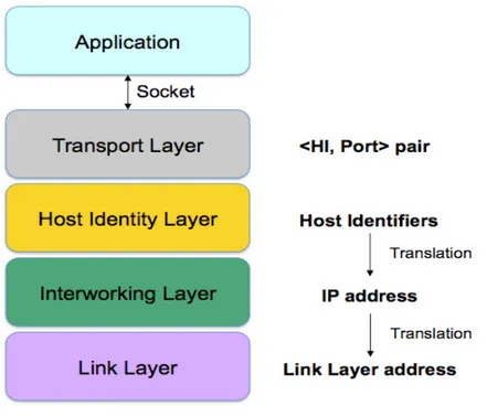
Host Identity Protocol (HIP) architecture - RFC 4423 - defines a new global Internet namespace which uses public/private keys, instead of IP addresses, as Host Identifiers. HIP provides a solution to the flexibility limitation of the current Internet architecture by decoupling the double role of both topological locator and network interface identifier currently filled by IP addresses.
In the HIP architecture a Host Identity layer is introduced between the Transport layer and the Network layer so that a different binding of transport layer protocols is provided (Figure 1.3). The transport-layer associations, i.e., TCP connections and UDP associations are no longer bound to IP addresses but to Host Identities. In this architecture the end-point names and locators are separated from each other. IP addresses continue to act as locators while the Host Identifiers take the role of end-point identifiers. Host Identifiers are locally mapped to the corresponding IP addresses and are used as source and destination addresses in the IP packets. In other words, HIP aware applications can bind their sockets directly to a <Host Identifier, Port> pair and they never see the actual remote IP address.
Since Host Identities can be bound to different IP addresses, with HIP, all existing transport associations can be easily moved to one address to another if one address becomes unreachable or if a new address become available. Consequently, HIP provides for interworking mobility and multi-homing without requiring additional mobility management signaling.
Furthermore, HIP provides for process migration and clustered servers. Indeed, it is possible to move all the active transport associations if a Host Identity is moved from one physical computer to another. Similarly, with HIP it is possible to distribute a Host Identity over different physical machines to provide clustered-based service without changing the client end-point.
Figure 1.3: HIP Stack architecture
1.2.4 Application layer
1.2.4.1
SIP re Invite
According to the SIP protocol, an INVITE message is sent by a terminal to its correspondent to setup a communication session. The traditional SIP mechanism to provide terminal mobility during an active session [13] involves not only the MT but also the CT, which is the other party engaged in the call. It foresees that the MT sends another INVITE message to the CT to communicate the information about the new parameters of the communication session after the handover. Although this solution solves the problems of Mobile IP, it has some drawbacks too. The second INVITE (commonly referred to as “Re-INVITE”) is sent end-to-end, and this could lead to high delays. Moreover, the handover procedure relies on the capability of the CT to handle this procedure.
Other SIP-based approaches have been proposed to manage mobility, addressing the shortcomings of the end-to-end “Re-INVITE” mechanism. For example, in [14] it is assumed that the MT connects to the Internet through different ANs and that each of them has its own so-called “Base Station”. The Base Stations are able to handle the vertical mobility and perform a handover, by moving a communication from a base station to the other. Actually, the handover procedure is split in two phases. First the MT contacts the old Base Station and
asks to receive/send packets over the new AN, using an INVITE message, which makes use of the JOIN SIP header [15]. For a certain time, media packets will be duplicated and sent over both wireless networks. As soon as the packets reach the MT through the newly activated interface, a re-INVITE message is sent by the MT to the CT through the new Base Station. Then, the media will flow through the new Base Station and over the new Access Network; a SIP BYE message will be sent to close the session with the old Base Station and a REGISTER message will be sent to the user “home” Registrar server to update the user contact information. This solution improves the performance of traditional SIP mechanisms in terms of handover duration and packet loss, but it still requires the involvement of the CT. Also, it requires a complex sequence of SIP transactions (INVITE, “Re-INVITE”, BYE and REGISTER) for each handover and it does not address NAT traversal issues.
In the following section we will see how our proposed SIP based Mobility Management solution tries to overcome these limitations.
2
MMUSE: Mobility Management Using SIP Extensions
In this Chapter we present the main features of MMUSE (Mobility Management Using Sip Extensions). MMUSE is our Mobility Management solution based on ad-hoc extensions of SIP protocol in order to support mobility. We presented this extensions in at the IETF (Internet E Task Force) in two drafts [4] and [5] in order to standardize its.
2.1
MMUSE overview
Let us consider the reference scenario depicted in Figure 1.1. A MT is equipped with multiple network interfaces; each of them is assigned and uses a different IP address, when connected to different Access Networks. The MT uses the SIP protocol for the setup of multimedia sessions. Our aim is to allow MTs to move among access networks (both wireless and wired) taking into due account the requirements listed in Section 1.1.
We focus our attention on a scenario including a so-called Session Border Controller (SBC). A SBC is a device typically located at the border of an IP network which manages all the sessions for that network. An SBC may perform several functions; for example it can provide NAT traversal features and privacy for the users of the internal network, by hiding the network structure behind it. It is an important component of several VoIP solutions. The SBC can be used by an enterprise, to allow its hosts located in a private network to make and receive calls or can be used by a public VoIP provider to offer VoIP services to enterprises.
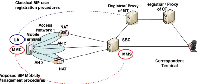
Our basic idea is to extend the signaling and media functionalities of the SBC in order to manage mobility. To this aim we introduce a new entity, called Mobility Management Server (MMS), within the SBC (MMS functionality are shown in 2.2.2). We also assume that the MMS cooperates with another entity that we introduce within the MT, called Mobility Management Client (MMC) (see 2.2.1). Both the SIP User Agent (UA) on the MT and the one on the CT remain unaware of all handover procedures, which are handled by the MMC and the MMS. On the MT, the UA just sees the MMC as its outbound proxy and forwards the normal SIP signaling and media flows to it; the MMC relays them to the MMS/SBC; from there on they follow the path determined by the usual SIP routing procedures. The MMS/SBC is a permanent anchor point both for signaling and media; we note that its presence is needed in any case to allow NATed UAs to be reachable. Figure 2.1 shows the architecture of the proposed solution, where the SBC is able to act as “meeting point” between the CT and
the MT, independently from the Access Network(s) on which the MT is located. For the sake of simplicity, in Figure 2.1 we only show a single “centralized” SBC/MMS, while a real world solution would take into account the scalability issues. A set of coordinated SBC/MMS needs to be deployed to cover the needs of a large number of mobile users.
SBC MMS NAT MMC Registrar/ Proxy of MT Registrar / Proxy of CT Mobile Terminal Correspondent Terminal Classical SIP user
registration procedures
Proposed SIP Mobility Management procedures UA NAT Access Network 1 AN 2 AN 3
Figure 2.1: Architecture of the proposed solution
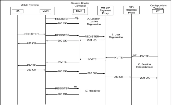
We have also defined specific signaling procedures (detailed in section 2.3), exchanged between the MMC in the MT and the MMS, so that the latter entity is always informed about the actual location of the MT. In particular, every time that the MT moves across two access networks, a location update SIP message is sent to the MMS, and this is done over the new network, to make it possible to complete the procedure even if the old network is suddenly not available (see Figure 2.2-A). If the MMS receives a call addressed to one of its served MT, it will forward it to the correct interface, thanks to the state information that it keeps.
When the MT needs to change access network while it is engaged in a call, the procedure is almost identical, with the difference that in this case the MMC sends to the MMS a SIP message which contains the additional information required to identify the call to be shifted to the new interface (see Figure 2.2-D).
To minimize the duration of the handover, we duplicate the RTP flow coming from the MT during the handover, by using the MMC. When the MMC starts the handover procedures, it sends the handover request (a SIP REGISTER) to the MMS and, at the same time, it starts duplicating the RTP packets over both interfaces. In this way, as soon as the MMS gets the
handover message, the packets coming from the new interface are already available. The MMS can perform the switching in the fastest possible way and then send the reply back to the MMC (a SIP 200 OK). When the MMC receives the reply message, it stops duplicating the packets. We modified the time parameters of the retransmission procedure of the handover REGISTER message so that a fixed retransmission interval of 0.2s is used, thus minimizing the duration of the handover, even when signaling packets are lost.
As regards the regular SIP transactions, such as the establishment of a new session (see Figure 2.2-C), the termination of an existing session, or the registration with a specific SIP proxy (see Figure 2.2-B), they are kept unchanged, under the constraint that all SIP signaling has to pass through the MMC and MMS. These two entities modify SIP messages in order to mask the current position of the user and to direct both SIP signaling and RTP packets to the correct location, taking care of any NAT device in the middle of the path. As far as the SIP signaling is concerned, the MMS/SBC acts as a standard SIP proxy with additional functionalities. Instead, as regards the media, it behaves as a SIP Back-to-Back User Agent (B2BUA): it divides the media path in two parts and interconnects them; each UA is led to believe that the other party is located at the MMS/SBC address.
In MMUSE, the user location mechanism is split in two levels. The MMS/SBC has a complementary role with respect to the SIP Registrar/Proxy server of the traditional SIP architecture. The SIP protocol foresees that the SIP Registrar receives information about the location of the user, acquired during the registration procedure, so that the “inbound” Proxy server of the user can forward incoming requests to the user. Nevertheless, in our case this location changes every time that the MT switches to a different network. To provide a more flexible solution, we let the MMS control the movements of the MT among different access networks through an internal registration, and leave the Registrar/Proxy unaware of such movements, by using a contact information that always points to the MMS itself.
In this line of reasoning, we distinguish between the identification of the user and that of the MT. In the classical SIP architecture there is no such distinction: a user can have more than one terminal (i.e., SIP User Agent) active at the same time, at different locations, and all terminals are seen as “contact addresses” of the user. When a terminal changes its IP address, a registration is sent to the Registrar, which will simply change the “contact address” for the user. In our solution, as stated above, we want to separate the user level registration from the management of the MT mobility. Therefore, we need to explicitly identify the MT by introducing an identifier, called terminal ID. This identifier is representative of a MT and it is used by the MMS to identify the MT and to keep track of its location (IP address). This identifier does not need to be understood outside the context of the MMC-MMS relationship: the user SIP Registrar will receive a registration in which the “contact address” points to the MMS.
We developed the MMC as a separate entity on the mobile terminal, making it able to interact with the UA via SIP messages. The MMC communicates with the operating system; thus, it is aware of the interfaces that are active at a given time. The MMC has the task to select the preferred interface and to change it, if needed. The main advantage of this approach is that it does not require any modification to the UA.
Section 2.5 shows the possible handover criteria used in MMUSE. We have developed tree types of handover criteria:
1) Based on signal’s power (as shown in 2.5.1) 2) Based on quality of link (as shown in 2.5.2) 3) Based on location’s information (as shown in 0)
The proposed architecture, based on SBC/MMS, may suffer of scalability problems, especially because an SBC/MMS needs to have the media relay functionality for all MTs under its control. We are currently working on how to distribute the SBC/MMS functionality to address scalability issues, a possible solution of this problem is shown in section 4. Also, we observe that this problem is common to all other solutions that are able to provide NAT traversal also for symmetric NAT, (e.g. STUN-Relay/TURN): they need to introduce a media relay element. Moreover, adding a media relay on the path is needed anyway when it is necessary to provide lawful interception services.
2.2
MMUSE Architecture
The “traditional” way to perform application level mobility with SIP is using the “Re-Invite” mechanism. It requires that the correspondent terminal is able to perform the handover, under the control of the mobile terminal. This approach does not match very well with the requirements listed above, as: it does not care much about performance (the procedure is end-to-end); NAT traversal issues are not taken into account, it relies on the capability of the remote terminal, it does not provide any privacy with respect to user movements, soft handover is not considered. For these reasons we preferred to introduce the element called “Mobility Management Server” to handle the terminal mobility across different access networks and to assist in performing the handover procedure.
The fundamental concepts of the proposed solution can be illustrated with the help of Figure 2.1. Mobile Terminals (MTs) have access to different networks like WiFi, Cellular 3G (in the figure, AN1, AN2 and AN3 network), which can overlap their coverage areas. The MT has separate interfaces, each one dynamically receives its (private or public) IP address from the corresponding wireless network. Multiple network interfaces in the MT can be active at the same time making it possible to realize a “soft handover”. The MT logically contains the User Agent (UA, i.e. the SIP client) and a Mobility Management Client (MMC). The MT uses a Session Border Controller (SBC) to access VoIP services from IP access networks often based on a private IP addressing scheme and operating behind a NAT/FW box. The SBC contains a Mobility Management Server (MMS) which is the main entity controlling the user mobility. Thanks to the interaction between the MMC in the mobile terminal and the MMS in the SBC the device can move between IP subnets, allowing the UA to be reachable for incoming requests and to maintain VoIP sessions across subnet changes. The “CT” node shown in the picture is the Correspondent Terminal that communicates with the MT. SIP Registrar functionality that are not directly related to handover/mobility management procedures can be performed by an external SIP Registrar/Proxy, as shown in the figure. Obviously the MMS and SIP Registrar can be implemented in a single element if required.
2.2.1 The Mobility Management Client
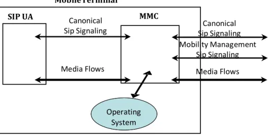
The Mobility Management Client is implemented as shown in Figure 2.3 as a separate entity running on the MT. The MMC hides all mobility and NAT traversal functionality to the
terminal SIP User Agent by relaying both signaling and media flows. In this case the SIP User Agent sees the MMC as default “outbound proxy” (which means that the UA will send all SIP message to the MMC) and it has no knowledge of the handovers. Existing SIP UAs can be easily supported/reused without any changes.
Operating System SIP UA MMC MobileTerminal Canonical Sip Signaling Media Flows Mobility Management Sip Signaling Media Flows Canonical Sip Signaling
Figure 2.3: The Mobile Terminal
In order to configure the IP addresses on the MT interfaces, existing mechanisms are used (e.g. PPP on the 3G interface, DHCP on WiFi LAN and Bluetooth PAN). When multiple interfaces are active, the MMC needs to select the preferred interface for sending/receiving the media flows (while the terminal is involved in a call) or for exchanging SIP signaling (both during calls and in idle state). The choice of the selected interface performed by MMC may depend on cost aspects and/or on QoS issues (signal strength, perceived packet loss and/or delay).
2.2.2 The Mobility Management Server
A SIP Session Border Controller is a session-aware device that manages SIP calls at the border of an IP network. It is aware of both signalling and media flows. An SBC may have several functions, one of the most interesting is solving the problem of NAT/firewall traversal, dealing with different NAT and/or UA behaviors. In this respect, an SBC provides NAT/firewall traversal without additional customer premise equipment, and without the replacement of existing firewalls and NATs. An SBC does not require any additional STUN/TURN node nor STUN/TURN protocol support, neither at UA nor at SBC side. Besides NAT traversal, the SBC may have several function, we will only list two of them: (i) the SBC can provide media interworking function for different media-related functionalities such as:
media transcoder, media encryption and protection against various media-based attacks; (ii) the SBC can provide signaling and media wiretapping system, which can be used to enforce requests for the lawful interception of communication sessions.
In order to manage the user mobility, we propose to add the MMS element into the SBC. The MMS is an “anchor point” for the media flows which are transmitted over the wireless access networks directed to (and coming from) the MT. When the MMC in the MT detects that a handover is needed, it will request the handover to the MMS (via a SIP message) over the “target” network. Then the MMS (in the SBC) will update its media proxy and will start transmitting and receiving the media over the target network (details are provided in the next section). Note that the entire handover procedure is handled by the MT and the SBC, letting the Correspondent Terminal (CT) (and other SIP intermediate nodes) completely unaware of what is occurring.
The SBC enhanced with the MMS is needed to manage MT handoffs between different access networks providing service continuity and NAT traversal. The SBC is able to process both SIP protocol header fields and Session Description Protocol (SDP) bodies in order to force itself as relay for the media packets.
2.3
MMUSE signaling aspects
This section describes the specific procedures for mobility management (off-call and on-call) and shows how the canonical SIP procedures (user registration and session establishment) are realized under the proposed solution. The procedure for mobility management related to the off-call part is meant to be used by the MT (UA+MMC) to tell the MMS about its current selected/active interface (or to communicate changes to such selection) when not in a call, for this we use regular REGISTER sent from the MMC to the MMS. The on-call mobility management related to the on-call part is meant to be used by the MT (UA+MMC) to tell the MMS about a change in its current selected/active interface when in a call, for this we use regular REGISTER sent from the MMC to the MMS with an additional "Handover" header which contains the reference to the active session(s) to which the handover is referred. In both cases an additional parameter to be added to the "Via" header for correct routing of responses to the MMC is needed and used.
2.3.1 Role of the Session Border Controller
From the point of view of SIP signaling, an SBC can act as a SIP B2BUA (Back-to-Back UA) or as a special SIP proxy. In the former case, the SBC works as an intermediate node that breaks the signaling path between two UAs and interconnects them (e.g. setting up a call) by means of establishing separate end-to-end connections between itself and each remote UA. In the latter case the SBC does not break the signaling path between the two UAs; instead it relays signaling requests and responses between remote UAs and other proxies, operating all SBC-specific function extending the normal proxy behavior as defined by RFC 2361. In addition to what is defined in the SIP standard for the operation of a SIP proxy, the SBC will modify the description of media session contained in the SDP, and some other SIP header fields like for example the Contact header field. Despite this extended behavior, obviously all outgoing signaling remains fully compliant with SIP standards. In our solution, we preferred to use a “proxy like” SBC as it is lighter and more “transparent” with respect to the SIP signaling among the endpoint UAs. The MMS/SBC behaves like a stateful proxy and it will receive ALL incoming and outgoing SIP messages to and from the mobile terminal. In particular it will process the incoming and outgoing INVITE messages used for setting up the calls.
2.3.2 Choice of SIP messages for Mobility Management
The procedures that need to be defined for mobility management can be classified as: out-of-call mobility management, call setup, in-call mobility management (i.e. handover).
The “traditional” SIP based mobility management foresees REGISTER messages for out-of-call mobility management, INVITE messages for out-of-call setup and RE-INVITE messages for in-out-of-call mobility management (i.e. handover). In our proposal we use REGISTER messages for both out-of-call and in-call mobility management and INVITE messages for call setup. There are two types of REGISTER message, one is related to user registration towards the user Registrar server, the second type of REGISTER is a “mobility” registration between the MMC and the MMS. The second type of REGISTER is used both in case of out-of-call mobility management and in case of a handover during an active call.
The user registration REGISTER messages and the mobility management REGISTER message should be distinguishable. In the implemented solution they are simply distinguished by the SIP destination (i.e. the SIP Registrar or the MMS. Moreover the in-call mobility management REGISTER also carries a reference to the active call which is under handover (namely the call reference).
2.3.3 Choice of terminal identifiers for SIP mobility management procedure
By means of the above described mobility management REGISTER messages, the SBC/MMS becomes aware of the current position of the MT, and can correctly route any new request or response messages addressed to the mobile UA. A key aspect concerning this procedure and its usage is the UA identification and addressing. In general a user may have more than one UA active, each one attached to a network with its own IP address (and SIP port). When sending a request or receiving a response, SIP usually identifies the users through the URLs present within the From and To header fields and through the request URI, while the actual address of the UA is normally present in the Via and Contact header fields. Unfortunately, neither the user URL nor the UA address can be used for UA identification since the former is not bound to a specific UA (more user’s UAs can be present) while the latter changes each time the UA moves from one network to another and, in presence of NATs, it is not unique due to the normal reuse of private addresses. For this reason a proper UA identification mechanism would be needed, but current SIP standard does not provide such mechanism. We used an identifier that the MMC inserts as an additional parameter inthe Via header, and it is denoted as Mobility Management ID (section 2.3.4.2). This information is processed by the MMS and needs to be understood only by the MMS itself. The CT (and the SIP registrar/proxy where needed) will handle this information in a completely transparent way according to standard SIP signaling. The details of the solution can be found in the next sections, which reports the complete SIP messages related to the various procedures.
2.3.4 Routing of requests and responses
In this section we detail how SIP messages are routed among the different entities. The challenge is to deliver incoming SIP requests and SIP responses to the MT, notwithstanding its mobility.
As for incoming SIP requests, when the UA in the MT performs the User Registration procedure (Section 0) the MMS rewrites the Contact header filed so that it points to the MMS itself. Therefore incoming requests for the MT will be forwarded by the SIP incoming proxy to the MMS. Similarly when outgoing requests are sent from the MT to a Correspondent Terminal the MMS will rewrite the Contact header so that the CT will consider the MMS as the destination of future requests to the MT. When incoming requests arrive to the MMS, the MMS will forward them to the current IP address of the MT, as updated by the MT using the Location Update procedure (Section 2.4.1). As for responses to outgoing SIP requests sent by the MT, the MMS adds a new parameter in the Via header field (see Section 2.3.4.2). This parameter is used by the MMS itself to route the response.
2.3.4.1
Use of Contact header field
The solution foresees that the MMS rewrites the Contact header when forwarding outgoing SIP requests coming from the MT. The rewritten contact address will have as host part the IP address (or domain name) of the MMS, and as username part a hint to the original contact address. This rewritten Contact header is compatible with SIP specifications, and it is reversible from the MMS. For example, assume that user's AoR is [email protected] and the original Contact header inserted by the UA is:
Contact: <sip:[email protected]:5080>
where x.y.w.z is the current IP address of the MT. The MMS rewrites the contact as follows: Contact: <sip:/TOKEN-user/AT-x.y.w.z/PORT-5080@MMS_x.y.w.z>
where MMS_x.y.w.z is the IP address of the MMS, "TOKEN-" is a string that can be set by the MMS and "/" is used as escape character. When receiving an incoming request with the request URI corresponding to the above contact, the MMS will extract the original contact address [email protected]:5080 and will forward the message according to the information contained in its MMS mobility database.
2.3.4.2
MMID parameter in Via header field
According to SIP specification, each node in the request delivery chain adds a Via header field with its own IP address when forwarding the request, in order to be included in the response delivery chain. We propose that the MMC adds an additional parameter to the Via header. This parameter is called MMID (Mobility Management IDentifier) and it carries the identifier of the MT. The MMID parameter is used as an indication that the originator of the request is a mobile terminal and it could change its IP address even during the transaction. Therefore the value of the MMID will be used as a key into the MMS mobility database, in order to find the current IP address to send the response. With this mechanism, the solution is able to deal in a seamless way with an handover performed during a session establishment. As an example, a Via header sent by the MMC to the MMS may look like the following:
2.4
MMUSE: SIP Procedures
As described in the previous section, the mobility management involves four main functional entities. On the MT sides there are the SIP UA and the MMC, while on the network side there are the SBC with the MMS and a SIP Registrar.
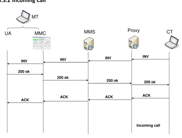
In this section we show the Sip Messages exchange among the various entities during the standard sip procedures (User Registration, Incoming and Outgoing Call) and during the specific mobility management procedures (Handover and Location Update procedure).
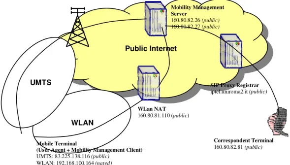
Figure 2.4 provides a physical representation of the scenario that will be used to describe the signaling flows and in Table 2.1 we show the IP addresses and the UDP port used from various Sip entities.
Mobile Terminal
(User Agent + Mobility Management Client)
UMTS: 83.225.138.116 (public) WLAN: 192.168.100.164 (nated)
Public Internet
SIP Proxy Registrar
iptel.uniroma2.it (public) Mobility Management Server 160.80.82.26 (public) 160.80.82.27 (public) WLan NAT 160.80.81.110 (public) Correspondent Terminal 160.80.82.81 (public) UMTS WLAN
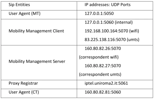
Sip Entities IP addresses: UDP Ports User Agent (MT) 127.0.0.1:5050
Mobility Management Client
127.0.0.1:5060 (internal) 192.168.100.164:5070 (wifi) 83.225.138.116:5070 (umts)
Mobility Management Server
160.80.82.26:5070 (correspondent wifi)
160.80.82.27:5070 (correspondent umts) Proxy Registrar iptel.uniroma2.it:5061 User Agent (CT) 160.80.82.81:5060
Table 2.1: Addresses of the SIP Entities
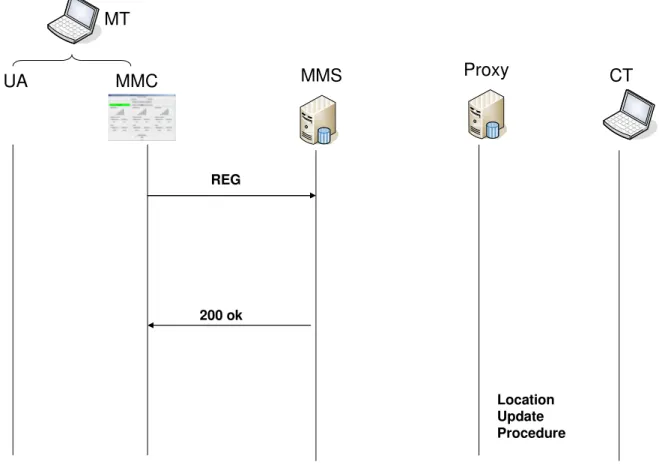
2.4.1 Location Update Registration: initial and “off-call” mobility
management
The Location Update Registration is the basic mobility procedure that allows a MT to notify the MMS about its “position” (or better its IP address) and select the currently preferred interface for sending/receiving SIP signaling and media flows. The sequence diagram of this procedure is shown in Figure 2.5. The MMC in the MT sends a Registration Request to the MMS over the “selected” interface. In the Request line of this message there is the address of the correspondent interface of MMS.
When the 200 OK is received, the “keep-in-touch” mechanism is activated on that interface (and deactivated on the previous interface if needed). This procedure is activated at the start up of the MT (or when the MT first enters in a coverage area), or whenever the MT wants to change the selected interface if it is under coverage of more than one network. We can refer to this procedure as “off-call” mobility management because we assume that terminal is not engaged in a call. If the terminal is engaged in a call, the handover procedure will be executed (see later on).
Note that the use of different IP addresses in the MMS corresponding to the different interfaces of the Mobile Terminal is not needed from the point of view of the mobility
management procedure. The reason to use the two IP addresses is related to a routing problem in the Mobile Terminal. Using two IP addresses on the MMS is a convenient way in order to easily select on the Mobile Terminal which outgoing physical interface will be used for sending out the IP packets (both signaling and media packets).
MMC UA MMS Proxy MT CT Location Update Procedure REG 200 ok
Figure 2.5: The Location Update Procedure
As result of the Location Update Registration procedure, the MMS becomes aware of the current position (i.e. IP address and port) of the MT, and can correctly route any new request or response messages addressed to the mobile UA (even across a NAT box). For each registered user the MMS stores the IP address and port from which it received the "Location Update" (LU) REGISTER. This information can be stored by the MMS in a table that we call "MMS mobility database" containing the MMS state. Such table is depicted in Table 2.2
User(terminal) IP/port
[email protected] 160.80.81.23:45678 [email protected] 87.3.235.212:23458
In section 2.3.3 and 2.3.4 we have introduced the problem of UA identification and addressing. In order to identify the UA, we used an identifier that the MMC inserts in the Contact and in the Via header fields, and it is denoted as MMID (Mobility Management IDentifier) in the SIP messages shown in Table 2.3
Register MMC to MMS
REGISTER sip:160.80.82.27:5070 SIP/2.0
Via: SIP/2.0/UDP 83.225.138.116;[email protected];branch=z9hG4bKd7bd1 Max-Forwards: 70
To: <sip: [email protected] >
From: <sip: [email protected] >;tag=4758d7f7 Call-ID: 4614a25233b6f9f5@user CSeq: 1 REGISTER Contact: <sip:[email protected]> Expires: 3600 Content-Length: 0 200OK MMS to MMC SIP/2.0 200 OK Via: SIP/2.0/UDP 83.225.138.116;[email protected];received=83.225.138.116 To:<sip: [email protected] > From:<sip: [email protected]>;tag=4758d7f7 Call-ID: 4614a25233b6f9f5@user CSeq: 1 REGISTER Content-Length: 0
Table 2.3: Location Update SIP Request
2.4.1.1
“Keep-in-touch” mechanism for NAT traversal
A “keep-in-touch” mechanism is needed to keep the pinhole in the NAT open. Various techniques can be used such as dummy UDP packets (from the MMC to the MMS or vice-versa), mal-formed SIP messages, well-formed SIP messages. This is a typical function of Session Border Controllers. We use periodic Location Update messages from MMC to MMS. The “keep-in-touch” packets are sent every 30 seconds, so they use a very limited amount of resources.
2.4.2 User Registration
This procedure consists in the UA registration with its own SIP Registrar server (the backend SIP registrar). The sequence diagram of this procedure is described in Figure 2.6. As any other SIP message, when the UA sends its own registration request to the SIP Registrar,
the message is sent by the UA to the MMC which is seen as outbound proxy. In the Request line of this message the IP address (or its fully qualified domain name) of the SIP Registrar is indicated. The MMC forwards it to the MMS. Acting on behalf of the MT, the MMS will forward the registration to the SIP Registrar, which will update the contact address associated with the user’s AoR (that is the public user identifier). When forwarding the Register message, the MMS/SBC modifies the Contact header in such a way it becomes the new “contact” for the user. This is required in order to force the routing through the SBC/MMS of all further requests addressed to the user. Such mangling of the contact URL should be unique and reversible. It can be done in several ways, using either a stateless approach (e.g. by mapping the previous URL, opportunely stuffed, within the new URL) or a stateful one (e.g. by using a local mapping table). We have chosen a stateless approach. The message “Registrar MMS to Proxy” of shows a rewritten contact. The contact has the format: <sip:/MMUSE-user/AT-83.225.138.116/[email protected]:5070>. As defined in section 2.3.4.1 it includes a Token that can be chosen arbitrarily (we used MMUSE), then it includes the “Mobility Management ID” of the UA as defined above.
From now on, only the MMS will keep track of the MT movements, while the SIP Registrar will just believe that the MT location is the IP address of the SBC as indicated in the contact URL.
MMC UA MMS Proxy MT CT 200 ok Registration User REG REG REG REG 200 ok 200 ok 200 ok
REGISTER UA to MMC
REGISTER sip:iptel.uniroma2.it SIP/2.0 Via: SIP/2.0/UDP
83.225.138.116:5060;rport;branch=z9hG4bK39A9DAE6366344A494795BAC9B3D7C5C From: user <sip:[email protected]>;tag=2872944525
To: user <sip:[email protected]>
Contact: "user" <sip:[email protected]:5060>
Call-ID: [email protected] CSeq: 1858 REGISTER
Expires: 1800 Max-Forwards: 70
User-Agent: X-Lite release 1105x Content-Length: 0
REGISTER MMC to MMS
REGISTER sip:iptel.uniroma2.it SIP/2.0
Via: SIP/2.0/UDP 83.225.138.116;[email protected];branch=z9hG4bKd7bd1 Via: SIP/2.0/UDP
83.225.138.116:5060;rport;branch=z9hG4bK39A9DAE6366344A494795BAC9B3D7C5C;receiv ed=127.0.0.1
From: user <sip:[email protected]>;tag=2872944525 To: user <sip:[email protected]>
Call-ID: [email protected] CSeq: 1858 REGISTER
Expires: 1800 Max-Forwards: 69
User-Agent: X-Lite release 1105x
Contact: "user" <sip:[email protected]:5060> Content-Length: 0
REGISTER MMS to Proxy
REGISTER sip:iptel.uniroma2.it:5061 SIP/2.0
Via: SIP/2.0/UDP 160.80.82.26:5070;branch=z9hG4bK443b8d64e Via: SIP/2.0/UDP 83.225.138.116;[email protected];branch=z9hG4bKd7bd1;received=83.225. 138.116 Route: <sip:iptel.uniroma2.it:5061;lr> Via: SIP/2.0/UDP 83.225.138.116:5060;rport;branch=z9hG4bK39A9DAE6366344A494795BAC9B3D7C5C;receiv ed=127.0.0.1
From: user <sip:[email protected]>;tag=2872944525 To: user <sip:[email protected]>
Call-ID: [email protected] CSeq: 1858 REGISTER
Expires: 1800 Max-Forwards: 68
User-Agent: X-Lite release 1105x
Contact: "user" <sip:/MMUSE-user/AT-83.225.138.116/[email protected]:5070> Content-Length: 0
200OK Proxy to MMS
SIP/2.0 200 OK
Via: SIP/2.0/UDP 160.80.82.26:5070;branch=z9hG4bK443b8d64e Via: SIP/2.0/UDP 83.225.138.116;[email protected];branch=z9hG4bKd7bd1;received=83.225. 138.116 Via: SIP/2.0/UDP 83.225.138.116:5060;rport;branch=z9hG4bK39A9DAE6366344A494795BAC9B3D7C5C;receiv ed=127.0.0.1
To: user <sip:[email protected]>
From: user <sip:[email protected]>;tag=2872944525 Call-ID: [email protected] CSeq: 1858 REGISTER
Server: mjsip stack 1.6
Contact: "user" <sip:/MMUSE-user/AT-83.225.138.116/[email protected]:5070>;expires=1800 Content-Length: 0 200OK MMS to MMC SIP/2.0 200 OK Via: SIP/2.0/UDP 83.225.138.116;[email protected];branch=z9hG4bKd7bd1;received=83.225. 138.116 Via: SIP/2.0/UDP 83.225.138.116:5060;rport;branch=z9hG4bK39A9DAE6366344A494795BAC9B3D7C5C;receiv ed=127.0.0.1
To: user <sip:[email protected]>
From: user <sip:[email protected]>;tag=2872944525 Call-ID: [email protected] CSeq: 1858 REGISTER
Server: mjsip stack 1.6
Contact: "user" <sip:[email protected]:5060>;expires=1800 Content-Length: 0 200OK MMC to UA SIP/2.0 200 OK Via: SIP/2.0/UDP 83.225.138.116:5060;rport;branch=z9hG4bK39A9DAE6366344A494795BAC9B3D7C5C;receiv ed=127.0.0.1
To: user <sip:[email protected]>
From: user <sip:[email protected]>;tag=2872944525 Call-ID: [email protected] CSeq: 1858 REGISTER
Server: mjsip stack 1.6
Contact: "user" <sip:[email protected]:5060>;expires=1800 Content-Length: 0
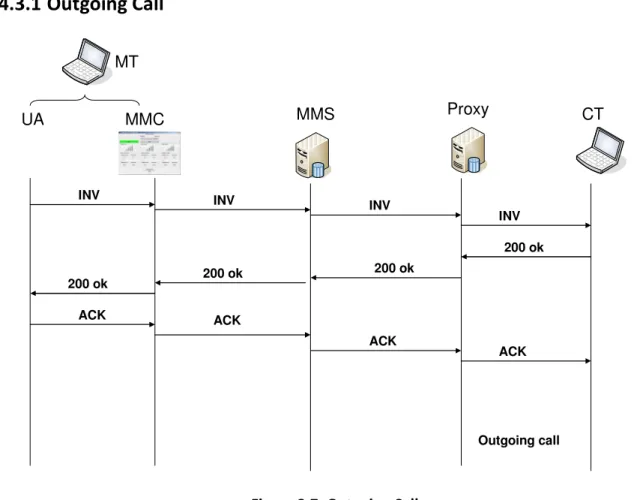
2.4.3 Session Establishment
The session establishment procedure consists in a standard SIP session setup procedure. All session establishment messages for MT are handled by the MMS/SBC. Before relaying an INVITE request sent by the caller and the corresponding 200 OK response sent by the callee the SBC modifies the corresponding SDP bodies in order to act as RTP proxy for media flows in both directions. This is needed to correctly handle NAT traversal in the path towards the MT, and it is done by exploiting the symmetric RTP approach as in a typical SBC implementation.
Once the session is established, the media packets start to flow over the selected wireless interface. In principle, there is no need to send anything on the unselected active interfaces, that should be used only when an “on-call” mobility procedure occurs. The MMS needs to keep a state information related to the active flows as it is performing a media relay functionality. In order to correctly perform the handover procedure, we require that this state information is accessible using the current call as key. SIP identifies a call by means of the Call-ID, the From and To header fields. Therefore the MMS maintains an "MMS call database". For each call and for each media flow the information of two "legs" (MT-MMS and CT-MMS) needs to be stored. For each leg the local and remote IP addresses and port of the media flows are stored. On the other hand our practical experience suggested that starting sending the packets on the 3G interface introduces an initial delay that can be quite large and can cause noticeable disruption in the voice communication during the handoff. Therefore we introduce a “keep-alive” mechanism between MMC and MMS during the call phase: the MMC sends dummy UDP packets to the MMS over the unselected wireless interfaces. The MMS will take care of discarding these packets.