DIPSI Workshop 2019 on Droplet Impact Phenomena & Spray Investigation, 17th May 2019, Bergamo, Italy
Patrick Foltyn*
1, Ferdinand Restle
2, Bernhard Weigand
11
Institute for Aerospace Thermodynamics (ITLR), University of Stuttgart, Germany
2Faculty of Aerospace Engineering, University of Stuttgart, Germany
*Corresponding author: [email protected]
Introduction
Contact angle measurements are used in order to investigate the wetting behavior of liquids on mainly solid surfaces. The wetting behavior is considered as hydrophobic if contact angles larger than 90° are determined. Hydrophilic behavior occurs for contact angles lower than 90°. For smooth surfaces, the measurement of apparent contact angles by the sessile drop method is very convenient in using only one shadowgraph.
However, this situation completely changes for structured surfaces since the three-phase contact line cannot be considered as circular due to pinning effects of the liquid to the structure. This has been already shown for grooves by Santini et al. [1]. In order to get a full knowledge of the apparent contact angle along the three-phase contact line, measurements over 360° degrees need to be performed.
In the following, the measured surfaces, the measurement devices and the acquisition and evaluation procedure is presented. Finally, the results are presented followed by a short conclusion and outlook.
Evaluated surface patterns
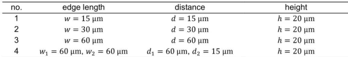
The evaluated surfaces have a generic roughness which is shown in Figure 1 and described in Table 1. The roughness is imposed on a polymeric wafer of Polycarbonate with the production method called hot embossing, [2]. This is done by the Karlsruhe Nano Micro Facility (KNMF) at the Karlsruhe Institute of Technology (KIT).
Figure 1. Evaluated structures for contact angle measurements Table 1. Summary of the parameters of the generic surface roughness of Figure 1
no. edge length distance height
1 2 3
4 , ,
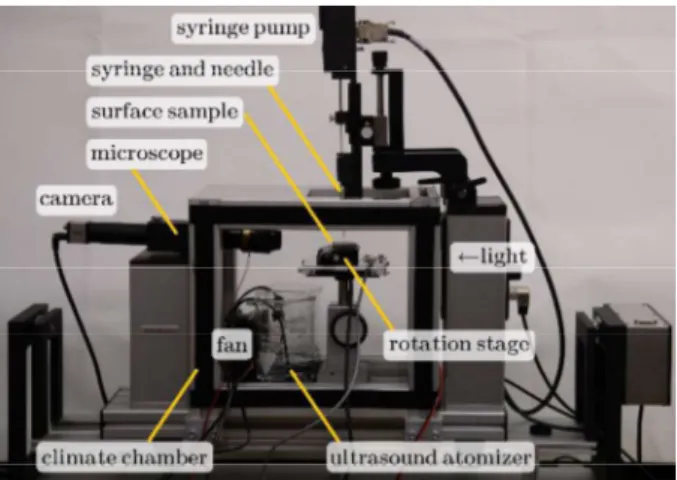
Measurement device
The measurement device is based on a commercial Optical Contact Angle measuring and Optical Contour Analysis (OCA) system. However, several modifications were necessary to be able to conduct contact angle measurements over an azimuthal angle range of 360°. The final setup is shown in Figure 2 in which also the modifications are indicated. In order to turn the surface sample, a rotating table was mounted on the height-adjustable table. Since the droplet needs to be stable over the whole acquisition, a climate chamber was added to the OCA. In combination with an active humidity generation by ultrasound atomizers, it can keep the relative humidity higher than 99 % almost fully avoiding the evaporation of the droplet. The fan is used to distribute the generated humidity as much as possible ensuring a homogeneous relative humidity. However, it has to be also
Squares (no. 1-3) Pillars (no. 4)
360° Evaluation of Projected Contact Angles of Static Droplets on Structured Surfaces
ensured that the airstream of the fan is not influencing the droplets shape. All optical components are heated avoiding condensation and thus optical aberrations. Finally, controlling and synchronizing of the camera and the rotation stage was accomplished by a program written in C++.
Figure 2. Measurement device with indicated main components to measure the contact angle over a predefined azimuthal angle range
Acquisition and evaluation procedure
Before the acquisition, the humidity chamber was sealed, the humidity was set higher than 99 % and the optical parts were preheated. For the acquisition, a droplet of 5 was generated, hanging on the tip of a blunt needle. The needle was slowly lowered in its vertical position in order to place the droplet gently in the middle of the structured surface, limiting the influence of the droplet placement to a minimum. After a short relaxation time of 10 minutes, the droplet was considered to be stable. During the acquisition, the rotation table was moved stepwise
for an angle step of and an image was acquired. Before each image was taken, a relaxation time of 1
second was included avoiding droplet movements like wobbling.
For the contact angle evaluation, only the two-dimensional images were used. The images were cropped and binarized. The detected edge of the droplet was divided into a left and right part, to be able to get left and right contact angles. The detected edges were used to fit an ellipse to the left and right side of the droplet with parts of the MATLAB toolbox of [3]. At the intersection between a predefined baseline and the fitted ellipse the angle was calculated. Between the two contact angles, no significant differences could be determined so that the arithmetic mean was used and which is shown in Figure 3. Additionally, the projected distances of the triple line dependent from the azimuthal angle is shown in the graphs.
Results
It is important to mention that the observed contact angle is the projected contact angle which can be seen in the two-dimensional images. Up to now, the liquid distribution of the droplet inside the structure cannot be observed. Right now a Cassie-Baxter state of the droplet is assumed. Therefore, it cannot be excluded that the liquid is
part -horizontal reference plane for measuring the real, for
flat surfaces, apparent contact angle. This has to be investigated with further experiments looking at the liquid distribution.
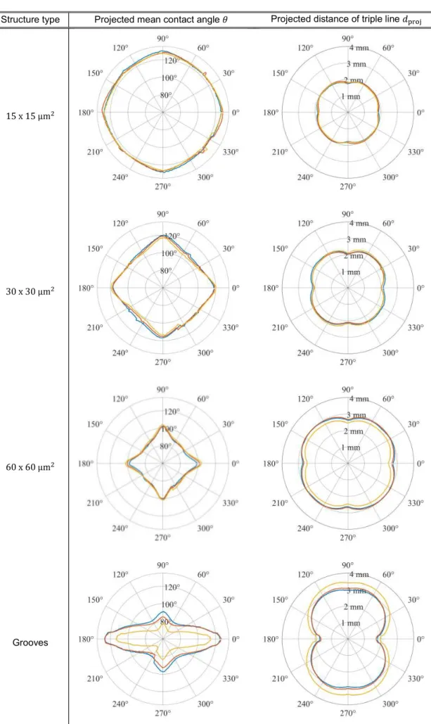
In the following Figure 3, the varying projected mean contact angle and the projected distance of the triple line is shown in dependency of the azimuthal angle . Four main results can be seen:
Firstly, the contact angle is getting larger for smaller edge lengths of the pillars, while is getting smaller.
Secondly, the contact angle variation decreases for smaller edge lengths. The variation for squared pillars with an
edge length of is approximately while for squared pillars with an edge length of is only . The
contact angle variation for the present grooves is even more significant with between the largest and the
lowest contact angle.
Thirdly, a non-circular baseline can be detected in evaluating in dependency of . Also here, the variation of
the grooves is the largest. For the squared pillars the variation is also more significant for larger edge lengths.
Fourthly, one can conclude that there is a link between the and . Larger contact angles can be found at
azimuthal angles at which is smaller and vice versa.
360° Evaluation of Projected Contact Angles of Static Droplets on Structured Surfaces
Structure type Projected mean contact angle Projected distance of triple line
Grooves
Figure 3. Results of measurements of projected mean contact angle and projected distances of the triple line
360° Evaluation of Projected Contact Angles of Static Droplets on Structured Surfaces
Conclusion and Outlook
The measurements have clearly shown, that a contact angle measurement on structured surfaces needs to be performed in a sufficiently high azimuthal angle range. One contact angle is not capable enough to describe sufficiently well the wetting behavior of the liquid on the surface. Reason for this is a non-circular baseline of the droplet which has, therefore, a varying contact angle as consequence. In this work, a possible measurement approach was briefly described.
Acknowledgments
The authors kindly acknowledge the financial support of this work by the Deutsche Forschungsgemeinschaft (DFG) in the frame of the International Research Training Group "Droplet Interaction Technologies" (GRK 2160/1: DROPIT)
Nomenclature
azimuthal angle contact angle
projected distance of the triple line References
[1] Santini, M.; Guilizzoni, M.; Fest-Santini, S. & Lorenzi, M. A novel technique for investigation of complete and partial anisotropic wetting on structured surface by X-ray microtomography Review of Scientific Instruments, 2015, 86, 023708
[2] Worgull, M. Hot Embossing: Theory and Technology of Microreplication (Micro and Nano Technologies) Elsevier, 2009
[3] Andersen, N. K. & Taboryski, R. Drop shape analysis for determination of dynamic contact angles by double sided elliptical fitting method, Measurement Science and Technology, IOP Publishing, 2017, 28, 047003