UNIVERSITÀ DEGLI STUDI DI CATANIA
Dipartimento di Ingegneria Elettrica Elettronica e Informatica
XXVIII Ph.D. Course in Systems Engineering
______________________________________________________
Carlo Famoso
Vibrational Control
of Large Scale
Electromechanical Systems
Ph.D. Thesis
Coordinator: Prof. Ing. Luigi Fortuna
Tutors: Prof. Ing. Luigi Fortuna
Prof. Ing. Mattia Frasca
Prof. Ing. Arturo Buscarino
Synopsis
In this thesis, our attention focuses on the fundamental role of broad-spectrum mechanical vibrations [1] to favor the working of complex electromechanical systems.
Uncertainty has been already proved to allow self-organization in array of non-linear oscillator (pendulums, in particular) [2, 3]. The idea of our thesis is to show that also passive and active mechanical vibrations can play a key role on self-organization in a class of complex electromechanical systems.
In fact, large-scale electromechanical systems considered in this work is referred to as imperfect
uncertain systems for which classical feedback control design cannot be suitably implemented.
For imperfect and uncertain systems, we mean systems including also unmodeled dynamics, intermittently arising, and uncertain parameters.
ii
In order to control arrays of such types of systems, made by coupling a large number of linear low order units, it is not convenient to consider classical control approach [4].
The strategy to control each unit with a local feedback loops, indeed, is not practical as it leads to numerous and different control actions.
On the contrary, the idea of our research is to use only few control actions, in order to control the whole system, by exploiting its intrinsic properties of self-organization stimulated by the control actions.
This work is organized as follows.
Chapter I is about the new class of systems that are experimentally realized. Some qualitative exploration about them has been also given with reference to the control task.
In the Chapter II the problem is introduced by focusing on the key points of the research and the peculiar aspects of the structures showing some introductive experimental results.
In the Chapter III the mathematical framework of the general class of imperfect uncertain systems and the control feedback scheme are discussed.
In the Chapter IV the models of specific investigated large scale electromechanical systems are illustrated.
iii
In the Chapter V the experimental results related to specific structures are discussed and compared with the numerical results obtained by simulations of the mathematical model.
Chapter VI includes the conclusive remarks and outlines the future perspective trends towards which this research could lead.
Contents
1 - Imperfect Uncertain Systems ... 1
Introduction ... 2
Examples ... 6
Understanding Imperfect Uncertain Systems ... 7
Main ideas to control imperfect uncertain system ... 12
2 - Overview of the Systems ... 17
Model of Coil ... 18
Mechanical supports ... 20
3 - Modeling and Control Strategy ... 27
General remarks ... 28
Mathematical model ... 30
Control strategy ... 32
Model of arrays of imperfect systems ... 34
4 - Large-scale electromechanical systems with passive and active vibrations ... 35
Specific Case Study ... 36
5 - Equipments and a gallery of experiments ... 41
Overview of the experimental setups ... 42
The starting up of the coils and generation of mechanical vibrations of the structures. ... 46
The rectangular structure: mechanical behavior ... 50
Sinusoidal Wave Signal ... 52
Triangular Wave Signal ... 53
Square Wave Signal ... 54
The circular structure: mechanical behavior ... 56
Single actuator ... 60
Square Wave Signal ... 60
In-phase Double Actuator ... 63
Square Wave Signal ... 63
Counter-phase Double Actuator ... 66
Square Wave Signal ... 66
The angular speeds of the coils and their regularization: Circular Structure ... 73
Single Actuator ... 75
In-phase Double Actuator ... 76
Counter-phase Double Actuator ... 79
Start and Control of the Circular Structure ... 83
The angular speeds of the coils and their regularization: Rectangular Structure ... 85
6 - Concluding remarks ... 91
1
1
______________________________________
Imperfect Uncertain Systems
In this Chapter a new concept in the class of
dynamical systems is introduced. The new class of
Imperfect Uncertain Systems is defined and
formalized. The possibility of controlling them is
examined.
2
Introduction
This work explores the possibility to control an introduced new class of systems. They are called imperfect
uncertain systems.
The subject derives from the simple observation that, even if it is well known the concept of uncertainty, the way to characterize uncertain systems - indeed the technological imperfection, the real world imperfections that involve the building of systems, or the verification that the real world objects are not equal with each others - leads us to make a set of considerations in order to understand their behavior and the strategy to be adopted, when imperfections prevent us from making a precise
system.
Indeed, in wider terms, we distinguish between two wide classes of systems. The class of systems that ‘does’
work and the class of the system that does not work! In this wide classification we intend mainly the idea of systems, which achieve stable equilibrium points and others that do not achieve them.
In our mind, perfection is intrinsic. The realization of perfect systems is a task that engineers follow. Improved technology leads us to work with more and more precise systems, which, of course, conduct us to work with quasi
3
to the lack of uncertainty and open loop control can be performed.
Efforts lead also to avoid disturbances to create the condition under which the system is insensitive to external noise by creating ideal conditions. Ideal Systems are the task of the next technology.
We can state that is the age of perfection! What really does comes out is that this is the recurrent concept of perfection from a philosophical point of view; it is a task that must be achieved, and in a parallel way the technological perfection has followed the philosophical concept.
Today, the age of technological perfection is a day-by-day task that must be accomplished. Examples are in Electronics and in Micro-machinery Mechanical Technology. Nanotechnology has a common task. It is the one to work in a small and small size dimensions, by achieving in a precision task what the chemical reaction of solid state physical system works in a controlled way.
Moreover, what appears in the ideas of the twentieth century from a philosophical point of view is the trend that perfection ideas have changed, a trend of non-idealist perfection arises and, partially, the idea of perfection has been reviewed.
4
This is due to various reasons: first of all, the review of science, the new concept of Statistical Physics, the Quantum Physics and the Gödel’s theorem have contributed to this new review. In addition, History, Anthropology, Social Sciences lead to perfection to be
reviewed. From another point of view, the world of things goes towards another direction to stress the technology to be perfect. And it is impossible. We know that uncertainty is real, and, what is more, uncertainty and imperfection go on together.
In this work, after having distinguished the concept of uncertain and imperfect systems, a strategy to get model of this class of system is faced. The concept of this class of systems will be stressed. The possibility to control them, in order to make them working, or better to make them working in stable equilibrium point will be discussed. In order to achieve this target, the new concept of additive
chimera dynamics will be introduced.
In this scenario, the central role of noise in formulating the control strategy will be widely approached. And the idea to propose a based noise feedback controller will be advanced. Therefore, a general theory to identify and to control this class of system will be outlined.
The work will illustrate the proposed strategy for the control of more structures of electromechanical systems.
5
Moreover, it will be emphasized that, even if the introduced theory has been to design control systems, the main concept of it is very useful to derive a new class of systems whose behavior is due to the role that uncertainty, noise and imperfection play.
6
Examples
The ideas of considering imperfect uncertain systems arouse from observations and experiments. In fact, let us consider the following examples:
1) Wheel on road; 2) Duffing systems; 3) Electrolytic Cell; 4) Multipliers.
The general consideration is that ideality and the search of perfection cannot offer emergent condition in order to get unexpected behavior of system.
7
Understanding Imperfect Uncertain Systems
Inside the technical concept, inside the previous item, there are some intrinsic questions related to the question. Indeed, the problem we are approaching is to achieve some performances inside the problem of determinism against indeterminism. In this case the occurring of the events in the real life happens as if it were not due to the sufficient condition for which they should occur the same as classical determinism wants it to be.
This determinism developed in the 18th century under
the formulation that each event is caused by a precise
action. This leads to conceive the idea that the future can be foreseen. Indeed, the formulation is not correct, because the causality relation allows us more interpretations. In fact we cannot exclude that the events are caused in a non-deterministic way, where the cause does not determine the effect; moreover, it increases the probability that they may occur. This leads to the introduction of stochastic systems.
There is a universal agreement both referring to the classical Physics and the Quantum Mechanical Physics that the not-determinism is related to measurements, and therefore it is related to the measurement precision and to the degree of measurement approximations.
8
Therefore the main idea is to consider in the proposed study the guidelines to examine the real systems related to the concept of imperfection and uncertainty.
Indeed, in the suggested definition, the qualitative behavior of the system, the possible causes that can arise to change its behavior are well known. We are conscious of the parametric uncertainty of the system.
As a result, the state equations of the system are known and, in any case, a mathematical model of the system is met. The key point is to understand in which way imperfections work.
What are imperfections? Imperfections are all the
ingredients that make the system not perfect.
The following features characterize imperfect systems: 1. They are dynamical systems;
2. To have an hidden parasitic dynamics; 3. They contains more threshold components;
4. More parameters are suddenly changed by external stochastic noise.
5. More parameters are depending on the working conditions;
6. An intrinsic network of switching effects leads the system from one behavioral condition to another one;
9
7. Silent dynamics characterize them. This is the key point of imperfect systems. We have called this dynamics Chimera dynamics that will help to control all the system;
8. Intermittency behavior characterizes the dynamics of imperfect systems.
Even if we dealt with continuous time imperfect systems, the main concept of imperfect systems would be quite general.
The condition of dynamical set of system is in any case fundamental.
Until now, it has been given a quite general idea of the system we have dealt with; the following parts of the manuscript soon will report various cases of imperfect systems and will introduce the mathematical items which let describe them.
In the next part of this session, attention to the
concept of uncertainty will be paid.
The uncertainty in our discussion, is quite different from imperfection. Therefore, the two concepts must be distinguished.
It is assumed that uncertainty is due to the
10
It should be caused by behavioral conditions, this are related to time varying physical parameters of the system and in any case it is assumed that we do not approach this aspect by using stochastic models. It is postulated that uncertainty exists!
Of course, in an ideal case we do not have uncertainty and we have to consider only a perfect system! And, even if the effort of the system designer is to achieve the goal to have certain and perfect systems, it is not generally that. Good approximation will be performed and in this cases the classical approach control theory, robust or not achieve good successes.
Summarizing the previous concept, we can state that for that class of systems, we understand its working mechanism deeply.
The coupling of ideal systems and non-ideal must be well known. This means that the equations of both the main systems and that of the chimera dynamics must be known and identified.
The central goal must be clear; this means that the controlled behavior of the system must be fixed and the limitation of the control of imperfect uncertain systems must be very clear to the user and to the control engineer.
This implies to face the problems of the control of this class of system with real consciousness of their limits and
11
to establish the performance limits that these systems can achieve. Moreover, new paradigms of control schemes must be adopted to get a correct compromise between behavior and performances.
Even if some ideas will arise in dealing with
imperfect-uncertain control systems, some essential facts must be taken into account.
First of all, to guarantee the good behavior of them, second to achieve suitable control performances. To keep into account the constraints that have to keep into account, like energy consumptions, the limitation of mechanical stress and so on. The sensor-actuators performs constraints.
12
Main ideas to control imperfect uncertain system
To face a new control problem, first of all, when the problem is new, a global view of it must be done. This means that in order to understand what to do, a wide range of scenarios must be taken into account and both the possible mathematical model and the physical knowledge of wide examples of systems must be evaluated. This means the control strategy must be accurately evaluated and new ideas must be focused.
This means that even main control strategies have to be the main guidelines of the problem, new ideas and new control paradigm must be established also for simplify the problem and to achieve suitable results.
Some concepts must be considered in the control science.
Indeed in dealing with the considered system, we are going to face a crisis. More of concept to have in our back ground fail. It means that to control an imperfect uncertain system implies to make real criticism of more the theories has been developed.
This is perceived in dealing with real evaluation of the system, or the possibility to achieve the control aims in front of the lack of the main ingredients that classical theory new or old must involve.
13
Indeed, in order to give some responses to the previous questions, something must be done.
First of all, new attempts to model the previous class of systems must be kept into account. Even if classical mathematical models help us to understand and to write preliminary models, for this class of systems, it is not sufficient to have the only help of equations and physical relationships to model them.
During the development of each science, the old paradigms must be accepted and prove the experiment solutions that are accepted. Further developments require both the building of particular equipments and also a new scheme of terms and of techniques that lead us to a proposal that decrease the similarity with the usual adopted scheme.
This last consideration lead us to consider a bifurcation in the paradigm we are usually using and the developments of new paradigms to face the problem. This route has been performed in order to develop the main guidelines to approach imperfect uncertain systems.
In accordance with the previous consideration, new paradigm of modeling and control must be adopted for this new type of systems.
14
Indeed the following items must be identified:
1. The perception of chimera dynamics. This is the key point. This aspect can involve the definition of its modeling. Indeed, the accuracy of the model is not a key point. When we discuss of modeling of chimera dynamics, we intend an approximate models or a qualitative models that responds to the behavior of the dynamics.
2. To achieve the reasonable knowledge of the system, in order to understand as chimera dynamics can be stimulated.
3. To understand the dynamics of the system to be controlled and to pay attention to the interaction of its variations part in order to establish the real relationship between systems and chimera dynamics. 4. To establish the strategy to control the system. In
general this concept is well known, in our discussion we remark that the control law is established by the chimera dynamics. Therefore our task is to generate the control strategy in order to stimulate and to control the chimera dynamics. Our task is therefore to develop the control strategy in order to be guaranteed that the chimera dynamics does work in order to control the main system. The problem is in this way is reversed. New paradigms arise.
15
5. The first one is to get qualitative model of the system. This can be done by analogies and therefore to make a comparison with well know model of systems that work like the considered one or to establish new models based on cognitive approaches of the main system. The discourse about the chimera dynamics has been previously discussed.
6. In order to establish the control low, it should be conceived as an on-off control law where the compensator generates sequences of signals in order to stimulate the chimera dynamics.
At this point of discussion - we do not go into the details of the design control strategy - we must take into consideration the philosophy of the controller that based on few measurements signals, have to generate the exciting strategies of the chimera dynamics.
7. The control of this new class of system can reflect the main items of the classical control scheme; moreover the following items must be achieved:
a) The performances of the system are limited;
b) The correct behavior of the system should be strange and guaranteed also by considering the robustness in terms of stability of the system. c) The energy management and optimization of the
16
8. In order to achieve the previous items, a suitable set of measurements must be taken into account, moreover only few control action must be performed, indeed the real multi loop control action are performed by the
17
2
______________________________________
Overview of the Systems
In this Chapter a description of the investigated
large-scale electromechanical systems and the
findings that motivated our research are given.
18
Model of Coil
The considered systems are
weight mechanical structure that supports very simple rotating coils. With this term we indicate coils, which are realized with few turns of a copper wire.
The i-th coil can be described with a nonlinear dynamical model:
where:
• Xi (i = 1, . . . , N with N indicating the number of
coils) represents the phase of the coil;
• Yi the angular velocity;
• J the angular momentum; • K the damping factor;
• Ia is the current flowing into the coil and is given
by:
18
are essentially based on a low weight mechanical structure that supports very simple rotating coils. With this term we indicate coils, which are realized with few turns of a copper wire.
coil can be described with a nonlinear
(1)
(i = 1, . . . , N with N indicating the number of represents the phase of the coil;
the angular velocity; J the angular momentum; K the damping factor;
19
with
• Va the voltage supplied to the coil;
• S the coil area;
• B the magnetic field;
• Ra the contact resistance, which, due to the coil
construction constraint, is nonlinear:
4 Ω <
10 Ω ≤
The coils have a diameter of 20mm, while cylindrical Neodymium magnets (N45) are used, which, at 1cm from their surface, provide a magnetic field of intensity B=0.0276T.
20
Mechanical supports
The structures into consideration are of the type shown in Fig. 1.
Figure 1 - Structures supporting the coils: (a) rectangular structure with 5 slots; (b) rectangular structure with 10 slots; (c) circular structure with 16 slots.
They consist of two trails
with a set of N slots which host the coils. The trails also allow electrical power to be supplied to the coils. Magnets associated to each coil are located o
the setup.
Figure 2 - Detail of the coupling
These structures are classified in the family of
scale dynamical systems, in the sense that the low weight
20
structures into consideration are of the type
Structures supporting the coils: (a) rectangular structure with 5 slots; (b) rectangular structure with 10 slots; (c) circular structure with 16 slots.
They consist of two trails (rectangular or circular) with a set of N slots which host the coils. The trails also allow electrical power to be supplied to the coils. Magnets associated to each coil are located on the bottom part of
coupling permanent magnet-coil
These structures are classified in the family of large-, in the sense that the low weight
of the structure, including the coils, is negligible with respect to the volume.
The tasks that we want to achieve are, at the first step, the complete start up of the various coils and, then, the regularization of the angular speed of the coils. As we will discuss in the following, in fact, both tasks are not trivial.
The mechanical supports are flexible structures [5] with natural modes having the main frequency around 5Hz (rectangular structure
The coils, ideally represented by the model in equation (1), must be considered nonlinear uncertain systems, due to the practical difficulties in building identical coils.
Figure 3 – Detail of the slot rectangular structure
Another source of uncertainty derives from the fact that the coils are located in the mechanical structure, which is free to move in all the three directions. Moreover, the slots, where the coils are lo
other (Fig. 3)
21
of the structure, including the coils, is negligible with The tasks that we want to achieve are, at the first step, the complete start up of the various coils and, then, the regularization of the angular speed of the coils. As we will discuss in the following, in fact, both tasks are not chanical supports are flexible structures [5] with natural modes having the main frequency around
structure) and 7Hz (circular structure). The coils, ideally represented by the model in equation (1), must be considered nonlinear uncertain systems, due to the practical difficulties in building
Detail of the slot, where the coil s are located, in
Another source of uncertainty derives from the fact located in the mechanical structure, which is free to move in all the three directions. Moreover, the slots, where the coils are located, are different each
22
All these factors contribute to create tremendous adverse conditions to attain a reg
system. In particular, depending on the initial conditions and system parameters, when the power is switched on, typically it occurs that some coils start rotating, while others do not.
The idea is to design flexible structures that, mechanically excited by their self
coils which are not working to receive solicitations that make them able to overcome the initial (electromechanical) inertia and start rotating.
This should occur through a global action deriving from the mechanical vibrations that couple each coil with the other. Therefore, the mechanical vibrations should favor the self-organization of the system in order to overcome the effects of the uncertainties.
Figure 4 - Two structures with 5 coils coupled through two springs.
22
All these factors contribute to create tremendous adverse conditions to attain a regular behavior of the system. In particular, depending on the initial conditions and system parameters, when the power is switched on, typically it occurs that some coils start rotating, while The idea is to design flexible structures that, echanically excited by their self-oscillations, allow the coils which are not working to receive solicitations that make them able to overcome the initial (electromechanical) This should occur through a global action deriving om the mechanical vibrations that couple each coil with the other. Therefore, the mechanical vibrations should organization of the system in order to overcome the effects of the uncertainties.
As far as the start up phase is concerned, the three structures of Fig. 1 show a different behavior.
Figure 5 – The Circular structure with sensors
In particular, in the structure of Fig. 1(a) the mechanical vibrations elicited by those coils that start when the power supply is switched on are enough large to let also the other coils to start. So, in the structure of Fig. 1(a), over a relevant number of trials un
power supply conditions, the various coils work.
The same behavior is observed, when more structures of this type are coupled (
springs. A global start up of a system with 10 coils can be achieved, while for the structure of Fig. 1(b), also having 10 coils, an active solution has to be envisaged.
23
As far as the start up phase is concerned, the three structures of Fig. 1 show a different behavior.
The Circular structure with sensors and actuators.
r, in the structure of Fig. 1(a) the mechanical vibrations elicited by those coils that start when the power supply is switched on are enough large to let also the other coils to start. So, in the structure of Fig. 1(a), over a relevant number of trials under the same power supply conditions, the various coils work.
The same behavior is observed, when more structures of this type are coupled (Fig. 4) by using mechanical springs. A global start up of a system with 10 coils can be structure of Fig. 1(b), also having 10 coils, an active solution has to be envisaged.
24
In fact, the structure of Fig. 1(b) is mechanically and electrically coupled and, therefore, even if from the mechanical point of view the increased elasticity favors vibrations. If the same electrical power is applied, the start up phase is more critical and the self-generated vibrations in the system are not enough to let the complete start up of all the coils.
In order to overcome this drawback, a shock system actuated with a low power electromechanical transducer has been conceived to excite the mechanical structures to favor active vibrations and, therefore, to make the coils in the condition to be helped for the start-up.
The electromagnetic actuator is driven by a broad-spectrum signal. This signal works in the range of the natural frequencies of the mechanical system, to give a suitable electrical signal in order to stimulate in an active way the system to start. In Fig. 6 the proposed structures for control are illustrated.
Figure 6 - Magnification of the shock system used to induce active vibrations in the structures of Fig. 1(b) and 1(c)
In general, the project will consist of coupling a great number of coils in various configurations
possibility to favor the self using different ways such as self
structure, passive coupling and active generation of mechanical vibrations.
The project is conceived in order to design an experimentally a system with hundreds of coils.
The main idea is to establish the conditions under which a global behavior can be obtained in high order structures of coils by exploiting the self
principle and using passive low power
fluctuations or external powered devices; this latter solution is needed only during the complete start
system. Moreover, assured the start regularization is then considered.
25
Magnification of the shock system used to induce active vibrations (b) and 1(c).
In general, the project will consist of coupling a great number of coils in various configurations to study the possibility to favor the self-organization of the coils by using different ways such as self-elicited oscillation of the structure, passive coupling and active generation of The project is conceived in order to design and realize experimentally a system with hundreds of coils.
The main idea is to establish the conditions under which a global behavior can be obtained in high order structures of coils by exploiting the self-organization principle and using passive low power induced fluctuations or external powered devices; this latter only during the complete start-up of the em. Moreover, assured the start-up, the task of speed regularization is then considered.
27
3
______________________________________
Modeling and Control Strategy
Chapter 3 is about the mathematical framework of
the general class of imperfect uncertain systems.
Also, control feedback schemes, for this type of
systems, are discussed.
28
General remarks
Before describing the mathematical model of the considered systems the following general definitions and remarks are given.
An imperfect uncertain system is a system for which the presence of imperfections, non-idealities and uncertainties has to be explicitly taken into account in the model so that to be able to represent the behavior observed in the real world system.
Let us consider, for example, the coils coupled through one of the flexible structures shown in Fig. 1. Ideally, the coils must be made by using symmetric copper windings, must have exactly the same geometry and have terminals which under ideal conditions must be 50% isolated and 50% conductor.
The magnetic flux should also be exactly symmetric with respect to the coil position. Moreover, the mechanical structure hosting the coils should have the ideal characteristics of a brush pivot mechanical system and, so, both sides of each coil (in particular, the geometry of their realization) must complain with the requirement of such ideal system.
However, this is not the real case. In fact, in dynamical conditions the pivot runs inside the brush reaching an equilibrium position, the pivot creeps rotating
29
in one side and in the other side. If the slots are not symmetric and geometrically perfect, then the coil moves from the equilibrium position and falls down.
Therefore, the ideal conditions modeled as in (1) have to be paired with a dynamics accounting for the onset of oscillations generated by the impacts of the coils sliding along their mechanical support and then collapsing into it. The coil motion inside the slots where they are located in fact is due to the geometrical imperfection of the mechanical structure and is the reason for which horizontal and vertical vibrations arise in the structure.
30
Mathematical model
From a mathematical point of view, an imperfect uncertain continuous-time system is a system described by a set of interacting state space equations, some of which modeling the imperfect dynamics.
Therefore, the model equations are:
, , , , ,
(2)
, , , , ,
where:
• x ∈ Rn is the state vector of the perfect system;
• x ∈ Rk is the state vector of the imperfect dynamics;
• u ∈ Rm is the vector of the exogenous control signals;
• w ∈ Rq is the vector of exogenous not controllable signals;
• p ∈ Rg is the vector of the system parameters, and:
• f : Rn × Rk × Rm × Rq × Rg × R → Rn • f : Rn × Rk × Rm × Rq × Rg × R → Rn
are nonlinear functions.
The block scheme representation of system (2) is illustrated in Fig. 7.
Figure 7 - Block scheme representation of system (2)
The imperfect uncertain systems have the following peculiarities: the parameter uncertainty may lead the
system to not work; the imperfect dynamics, if it is excited, can stimulate the system to achieve the suitable parameter condition in order to allow th
Therefore, from two factors usually considered as
undesired (that is, the presence of uncertainties and imperfections), an adaptive strategy may be attained that, on the contrary, is a positive factor favoring the system working condition.
Based on these considerations, the natural question that arises is: how to stimulate the dynamics due to the imperfections?
31
Block scheme representation of system (2)
The imperfect uncertain systems have the following
the parameter uncertainty may lead the system to not work; the imperfect dynamics, if it is excited, can stimulate the system to achieve the suitable parameter condition in order to allow the proper behavior of it.
Therefore, from two factors usually considered as (that is, the presence of uncertainties and imperfections), an adaptive strategy may be attained that, on the contrary, is a positive factor favoring the system Based on these considerations, the natural question that arises is: how to stimulate the dynamics due to the
32
Control strategy
In order to give an answer to the previous question, an approach inspired to the vibrational control theory [6, 7, 8] is proposed.
The principle of vibrational control is to modify the properties of the system in a desired manner by introducing external zero-mean perturbations.
Unlike conventional control approaches, vibrational
control does not require measurements of signals and disturbances, but does work in an openloop frame and essentially leads to the design of an exogenous signal such that that the original autonomous system does work as a non-autonomous one ensuring that stability and performance are obtained.
Indeed, a system is said to be vibrationally performing if there exists a periodic signal s(t) with zero-mean value that ensures the desired behavior of the system.
The scheme of Fig. 8 shows the control principle for an imperfect uncertain system.
Figure 8 - Control scheme for an imperfect uncertain system.
Exciting signals in a closed
stimulate the imperfect dynamics that exerts the real control action on the system.
With respect to vibrational control, we highlight the important difference that the control here acts in closed loop.
33
Control scheme for an imperfect uncertain system.
Exciting signals in a closed-loop scheme are used to stimulate the imperfect dynamics that exerts the real control action on the system.
vibrational control, we highlight the important difference that the control here acts in closed
34
Model of arrays of imperfect systems
The model of a 1D array of coupled imperfect systems can be written as follows, where, to point out the peculiarity and importance of imperfect dynamics, the model considers only a diffusive coupling acting on the dominant state variable arising from the imperfect dynamics:
, , , , , + , , + , ,
(3)
, , , , , + , , + , ,
where
• i is the spatial index;
• j is that of the dominant state variable related to
the imperfect dynamics.
The approach appears to work suitably in spatially-extended imperfect systems also in accordance with the good performance which are obtained for spatially-extended systems when open-loop classical vibrational control is applied to stabilize simultaneously all modes of oscillations [3].
4
______________________________________
Large-scale electromechanical
systems with passive and active
vibrations
In this Chapter models of specific investigated large
scale electromechanical systems are illustrated.
The mathematical model for an imperfect uncertain
system, with the actuated control signal, is
introduced.
36
Specific Case Study
As already mentioned, technological imperfections on the coils and on the supporting structure lead to the fact that coils are unable to overcome the initial electromechanical inertia and to start rotating.
On the other hand, the system may be considered to properly operate if and only if, after a transient time, all the coils are rotating. We remark that, if the power supply is sufficiently high, many coils will be operating because many of them will have a self-sustained start up and will induce in the mechanical structure a passive vibration that may change the angular position of the other coils and let them to start.
So, in this case the system will properly operate thanks to passive vibrations. From an experimental point of view by using unlimited energy, the event that in steady state some coils are not working is a rare one.
In the case that the energy is limited (the case of power energy supply optimization). It is common to find many coils not operating and, on the contrary, it is a rare case that the system is self starting.
This is the most interesting and realistic (as energy is limited) case, which requires the use of an external actuation, like that shown in Chapter 2, in accordance
with the control scheme of Fig. 8
Chapter 3, the control scheme operates in closed loop. For our specific case study, the control feedback makes use of information on the angular speed of the coils. In particular, the angular position of the first coil is the more critical due to the mechanical stiffness of the part where it is located.
Therefore, using this measured signal is convenient to close the control loop. The control will be performed until the first coil begins to rotate. Being the more difficult coil to control, its proper operation assures that all the system is working.
The mathematical model of the system with the actuated control signal, written in accordance with the previously presented general model, is now introduced:
1
+
with:
or
37
ith the control scheme of Fig. 8. As introduced in Chapter 3, the control scheme operates in closed loop.
For our specific case study, the control feedback makes use of information on the angular speed of the coils. In particular, the angular position of the first coil is the more critical due to the mechanical stiffness of the Therefore, using this measured signal is convenient to lose the control loop. The control will be performed until the first coil begins to rotate. Being the more difficult coil to control, its proper operation assures that all the system The mathematical model of the system with the l signal, written in accordance with the previously presented general model, is now introduced:
38
where
• Xi is the phase of the coil,
• Yi the angular velocity,
• Ji the angular momentum,
• Si the coil area,
• Bi the magnetic field,
• Va the voltage supply,
• Ii the current flowing into the coil given by
where Ri, the contact resistance, is such that
4 Ω <
10 Ω ≤
The signal u(t) is the combined effect of the control action on the system.
We emphasize that the quantities angular momentum, coil area, magnetic field and contact resistance are now indexed with a subscript to account for uncertainty in the system.
The main control items may be summarized as follows. Due to the uncertainty on the parameters and the random initial positions of the coils, there is no guarantee of the start up of all coils.
39
Therefore, an electromechanical broad-spectrum signal acting on the direction orthogonal to the axis of rotation of the coils has to be generated until the start up of each coil is attained. Moreover, in order to guarantee the steady state behavior a threshold signal is maintained. For this reason, the way in which the control action is implemented is such that it can takes two values: the first one (a high value) permits to stimulate the structure in a wide range of frequencies, exciting the imperfect dynamics; the second one (a low level) assures a passive action maintaining a residual vibration to favor regularization of the system behavior.
However, as the angular speed is very different from coil to coil, a further control action is also needed to regularize all the coil angular speeds.
Having identified that, to do this, the action must be performed on the system in a direction parallel to the coil axis, a control signal acting in this direction is also applied until the mean value of the angular speed of the coils is not maintained in a suitable range.
41
5
______________________________________
Equipments and a gallery of
experiments
In this Chapter the experimental results related to
specific structures are discussed and compared
with the numerical results obtained by simulations
of the mathematical model.
42
Overview of the experimental setups
The experimental setups for the study of the electromechanical systems dis
Fig. 9 and Fig. 10.
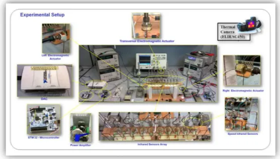
Figure 9 - Complete system setup including virtual instruments and infrared thermal camera to monitor coil angular speed, and control modules implemented on a microcontroller.
The first one consists of the electromechanical system of Fig. 1(b) supporting and powering
The second one consists of the electromechanical system of Fig. 1(c) supporting and powering N = 16 coils.
Both systems are provided to all the equipments for its control and measurement.
42
Overview of the experimental setups
The experimental setups for the study of the electromechanical systems discussed above are shown in
Complete system setup including virtual instruments and infrared thermal camera to monitor coil angular speed, and control modules implemented on a microcontroller.
The first one consists of the electromechanical system of Fig. 1(b) supporting and powering N = 10 coils.
The second one consists of the electromechanical system of Fig. 1(c) supporting and powering N = 16 coils.
Figure 10
In fact, these systems are equip
arrangement of TCRT5000 reflective optical sensors with transistor output, which includes an infrared emitter and phototransistor in a leaded package which blocks visible light. Infrared sensors monitor
coil by deriving their angular speed.
43
10 - Circular Structure
In fact, these systems are equipped with an of TCRT5000 reflective optical sensors with transistor output, which includes an infrared emitter and phototransistor in a leaded package which blocks visible light. Infrared sensors monitor the phase of each rotating coil by deriving their angular speed.
44 Figure 11 - TCRT5000 reflective optical sensors
The systems are also equipped with a thermal camera to monitor the overall system behavior.
Some electromagnetic actuators, driven by the control signals, are located on the mechanical structures.
In the rectangular structure with 10 slots, three electromagnetic actuators are used to activate the structure. The first two, placed on the two opposite abutments, provide respectively the high and low level control signals implementing the startup and maintenance control action, while the third actuator, placed orthogonally with respect to the mechanical structure, provides the transversal mechanical vibration implementing the regularization loop.
In the circular structure with 16 slots, only a couple of electromagnetic actuators are used to activate the structure. They are placed in correspondence of two non consecutive abutments of the inner circumference and
44
TCRT5000 reflective optical sensors monitor the phase of each rotating coil
The systems are also equipped with a thermal camera overall system behavior.
Some electromagnetic actuators, driven by the control signals, are located on the mechanical structures.
In the rectangular structure with 10 slots, three electromagnetic actuators are used to activate the placed on the two opposite abutments, provide respectively the high and low level control signals implementing the startup and maintenance control action, while the third actuator, placed orthogonally with respect to the mechanical structure, transversal mechanical vibration implementing the regularization loop.
In the circular structure with 16 slots, only a couple of electromagnetic actuators are used to activate the structure. They are placed in correspondence of two
45
provide the high and low level control signals implementing the startup and maintenance control action, in relation to the dynamics of the electromechanical system.
Figure 12 - Couple of electromagnetic actuators are used to activate the circular structure.
The control algorithm, for both systems, is based on the measurement of the angular speeds provided by the infrared sensors and processed through a STM32 microcontroller unit Nucleo [9].
Labview virtual instruments and Matlab tools have been used to process the data in order to evaluate the performance of the systems.
46
The starting up of the coils and generation of
mechanical vibrations of the structures.
Before discussing the experimental and numerical results, in order to exemplify the principle generating mechanical vibrations, some snapshots of a close up on the brush pivot system are discussed.
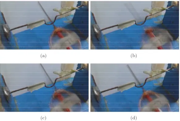
Figure 13 - Complete cycle of a single coil around the brush-pivot support: (a) fiction causes the rotating coil to climb the left part of the support, (b) gravity makes the coil falling down impacting the structure, (c) coil tends to climb on the opposite side of the support, and (d) falls down hitting again the support.
The frames shown in the Fig.13 refer to a complete cycle of a single coil rotating around its pivot. The frames illustrate the mechanism that leads to the stimulation, in the mechanical structure, of the imperfect dynamics
47
generating mechanical vibration both in vertical and horizontal direction. The effect of friction between the supporting trails and the coil is to lift it up along one of the sides of the support so that, when gravity makes the coil falling down, it hits the trail. The impact with the structure generates the vibration.
When the voltage is supplied to the coils, only few of them start to rotate since the magnetic torque is not enough to move from the rest position, the action of the first control loop is turned on and the structure is subjected to a strong broadband mechanical vibration induced by the first electromagnetic actuator.
When all coils are actually rotating, the control action is turned into the low level, still providing to the mechanical structure a weak broadband mechanical vibration: the action of the second control loop is then activated.
In the rectangular structure with 10 slots, the second control loop provides to the structure, through the third electromagnetic actuator, a transversal vibration with constant frequency in order to regularize the coil angular speeds.
In the circular structure, a suitable weak vibration with constant frequency, in order to regularize the coil angular speeds, is provided to the system through the
48
same electromagnetic actuators that generated the initial strong mechanical vibrations.
Figure 14 - Baumer OADM 12U6460/S35A laser distance sensor
In order to verify the effect of both passive and active mechanical vibration, a Baumer OADM 12U6460/S35A laser distance sensor has been used to measure the effective longitudinal vibration of the whole mechanical structure.
Figure 15 - Horizontal displacement of the whole structure measured through the laser distance sensor. The startup control action is turned off at T=30s.
The mechanical vibration in Fig.
in which the startup control is switching between
and low signals and clearly show the impact of the different action on the leve
structure.
49
Horizontal displacement of the whole structure measured through the laser nce sensor. The startup control action is turned off at T=30s.
vibration in Fig. 15 refer to the phase in which the startup control is switching between the high and low signals and clearly show the impact of the different action on the level of vibrations of the mechanical
50
The rectangular structure: mechanical behavior
In order to determine the mechanical behavior of the structure to the imparted stresses and define its resonance frequency, the actuators, which are positioned longitudinally, have been excited with different canonical signals at a varying frequency.
It was chosen to excite the system with a sequence of signals in ascending order harmonic components so as to highlight a possible filtering activities inherent in the system.
The signal was sent to the electromagnetic actuators via a power device capable to delivering the required current.
The tests were carried out by maintaining fixed the amplitude of all signals, while their frequency was made to vary within a range of significant values for the mechanical behavior of the structure.
The system’s response on abutments, opposite to those solicited, was detected using a laser measuring system that has returned a voltage, which was proportional to the displacement with respect to equilibrium (zero position) of the measuring point.
All involved signals were sent to a digital oscilloscope that allowed us to view them, make a first qualitative
51
estimate and calculate the FFT of the response signal in order to determine its harmonic components.
The obtained results are shown in the following figures.
52
Sinusoidal
WaveSinusoidal Wave Signal - 2Hz
Sinusoidal Wave Signal - 4Hz
Sinusoidal Wave Signal - 6Hz
52
Wave Signal
Sinusoidal Wave Signal - 3Hz
Sinusoidal Wave Signal - 5Hz
Triangular Wave
Triangular Wave Signal - 2Hz
Triangular Wave Signal - 4Hz
Triangular Wave Signal - 6Hz
53
Triangular Wave Signal
Triangular Wave Signal - 3Hz
Triangular Wave Signal - 5Hz
54
Square Wave Signal
Square Wave Signal - 3Hz
Square Wave Signal - 4Hz
Square Wave Signal - 6Hz
54
Square Wave Signal
Square Wave Signal - 3Hz
Square Wave Signal - 5Hz
55
From the analysis of the obtained results, in the preceding tests, it is clear how the structure presents in a precise manner a resonant frequency centered at about 4Hz.
In fact, either it be solicited with a monochrome signal, or with a broad-spectrum signal, as a square wave signal, the harmonic component, which emerges from the Fourier transform, is more marked at the frequency of 4Hz. Furthermore, if one observes the amplitude of the response signal of the system detected on the abutment, it is clearly noted that the elongations, relative to the position of rest, increase considerably when applying the system to each of the assigned signals to the frequency equal to the value of 4Hz.
From these results, we can deduce that, in order to implement efficiently the system and to transit all the coils in the state of rotation, the frequency of the actuating signal to be applied to the actuators must have a value that does not deviate from that one which has been found experimentally.
This ensures that the transition from the stopped state to the rotation takes place with the minimum energy administration by the external apparatuses to the structure, since, for the very principle of resonance, it will respond effectively to the solicitation.
56
The circular structure: mechanical behavior
A study about the mechanical behavior, similar to that seen for the linear structure, was conducted on the circular structure.
Given the particular shape of the structure and its specific spatial organization, the study has taken into account not only of the frequency with which the structure itself is mechanically stressed, but also the direction that the applied forces by the actuators must have, in order to obtain the best response from the structure as a whole.
Figure 16 - Actuators in correspondence of an abutment of the inner circumference.
The choice to position the actuators in correspondence of the abutments of the inner
57
circumference is dictated by the need to allow the stress to propagate towards the inner, smaller and more rigid circumference, as well as against the outer larger and more flexible one.
From tests carried out, it is seen that the presence of the actuators on the abutments of the inner circumference is effective for the entire structure, as the greater stiffness of the requested party requires that the applied forces are substantial, and also, only the coils of the inner circle will feel the effect.
Conversely, the positioning of the actuators on the abutments of the outer circumference, show an opposite behavior.
The major flexibility of the structure lets the solicitation be absorbed without transmitting it to the inner and standstill parts.
At the end, the choice fell on the abutments of the inner circumference, positioned in correspondence with a diametral plane, so as to exploit the central symmetry of the system.
In this configuration, the response of the system to the mechanical stresses of the actuators is detected on a abutment positioned at the plane perpendicular to that containing the solicited abutments.
58
The detection system is based on a laser system capable of returning, as an output signal, a voltage, which is proportional to the elongation of the target point, in relation to its zero position or stop.
The mode excitation of the electromechanical actuators is also optimized.
In the first practice the structure is stressed by means of only one of the actuators taken into account.
As can be seen from the obtained data, the response of the system is not very effective both in terms of response to stress and in terms of start-up of the coils.
Ultimately, in the light of the obtained data, the possibility of urging the structure with only one actuator is ineffective and unwrapped.
The structure is, therefore, solicited with two actuators. The excitation signal is the same for both actuators, so as to be certain that the conditions of consistency between the two sources are maintained, such as the same amplitude, frequency and phase.
This condition, together with the specific construction of the actuators that make them similar, allows the applying, in the two chosen points of the structure, of an electromechanical signal, which is consistent, in terms of frequency and amplitude, in the two sources.
59
A further diversification in the study of the mechanical behavior of the circular structure is the direction of the applied forces at points of stress.
It is assumed that the two actuators have an in-phase behavior, when the vectors of the applied forces in the abutments have the same direction with respect to the plane containing the abutments themselves.
We state that the two actuators have a counter-phase behavior, when the two vectors of the forces applied on the abutments are anti-parallel. The different mode of excitation of the two actuators results in a different mechanical behavior of the structure.
In the first case, the whole structure is brought to oscillate along the vertical plane of the active abutments.
In the second case, the central circle of the structure is affected by a twisting motion, with respect to the central axis, which leads the structure to traverse an arc of a circle equal to the displacement applied by the actuators. It is this configuration, among all, the one that gives the best results in terms of mechanical stress of the structure and start-up of the coils.
60
Single actuator
Square Wave Signal
Single Actuator – Square wave signal – 3Hz
61
Single Actuator – Square wave signal – 7Hz
62
Single Actuator – Square wave signal – 11Hz
63
In-phase Double Actuator
Square Wave Signal
In-phase Double Actuator – Square wave signal – 3Hz
64
In-phase Double Actuator – Square wave signal – 7Hz
65
In-phase Double Actuator – Square wave signal – 11Hz
66
Counter-phase Double Actuator
Square Wave Signal
Counter-phase Double Actuator – Square wave signal – 3Hz
67
Counter-phase Double Actuator – Square wave signal – 7Hz
68
Counter-phase Double Actuator – Square wave signal – 11Hz
69
Comparison between the various stresses at resonance frequency
Single Actuator – Square wave signal – 7Hz
In-phase Double Actuator – Square wave signal – 7Hz
70
On the previous tests with a signal
frequency, others were added in which the square wave forcing signal was made to vary in frequency, by ranging from 100mHz to 20Hz. The experimental results of these tests are entered in the following figure:
Figure 17- System response to a square wave forcing signal that was made to vary in frequency.
Together with the forcing signal and the signal of the laser sensor, which shows proportionally the relative displacement of the abutment, the tr
transform implemented on this last signal is also present. A further result about the dynamics of the structure is given from the study of the displacement of the abutment, when the structure is only subjected to the movement of the coils in rotation.
The acquisition of the signal of the laser sensor, detected in such a condition in correspondence to the
70
On the previous tests with a signal at an assigned frequency, others were added in which the square wave forcing signal was made to vary in frequency, by ranging The experimental results of these tests are entered in the following figure:
System response to a square wave forcing signal that was
Together with the forcing signal and the signal of the laser sensor, which shows proportionally the relative displacement of the abutment, the trend of the Fourier transform implemented on this last signal is also present.
A further result about the dynamics of the structure is given from the study of the displacement of the abutment, when the structure is only subjected to the
s in rotation.
The acquisition of the signal of the laser sensor, detected in such a condition in correspondence to the
abutment, is shown in the following figures, which indicate the processed and viewed signal in the digital oscilloscope:
Figure 18 - Displacement of the abutment, when the circular structure is only subjected to the movement of the coils in rotation
In the previous images, it is clearly visible how other higher frequencies are added to the fundamental one at 7Hz, but undoubtedly at a lower intensity.
Ultimately, from the study of the dynamic structure it has emerged that the structure itself presents
dynamics whose fundamental frequency does not depend on the one imposed by the forcing signal.
71
abutment, is shown in the following figures, which indicate the processed and viewed signal in the digital
Displacement of the abutment, when the circular structure is only subjected to
In the previous images, it is clearly visible how other higher frequencies are added to the fundamental one at 7Hz, but undoubtedly at a lower intensity.
Ultimately, from the study of the dynamic structure it has emerged that the structure itself presents its own dynamics whose fundamental frequency does not depend on the one imposed by the forcing signal.
72
In fact, from the previous graphs, it is clear how the dynamic of the structure is essentially one of a resonant type, capable of responding to a given frequency, typical of a proper oscillation.
The measures have led, therefore, to the determination of a system fundamental harmonic frequency to 7 Hz.
73
The angular speeds of the coils and their
regularization: Circular Structure
Let us now discuss the pattern of the angular speeds of the coils in the circular structure.
The measurements reported in Fig. 19 cover a period of 30s of the experiment from startup and show the variation of the average angular speed of each coil (the average is performed on a time window of 1s.)
The first problem faced is the choice of the type of stress applied to the system, or the manner in which actuators are excited, in order to ensure that, after a certain finite time interval, all the coils are in rotation and that has to be realized with the minimum input of energy from the power supply systems that provide the electrical power to the system itself.
The series of tests conducted on the system has been developed with the same methodology viewed for the determination of the resonance frequency of the system.
The actuators are energized in different ways and at different frequencies; the timing of implementation of the coils is detected and shows which of the applied signals and the manner of excitation provide the best response in terms of activation times.