Titolo
Dynam
i
c a
nalysis of an advanced, isolated NPP assu
m
i
ng
real HRDB properties
Ente emittente CIRTEN
PAGINA DI GU
A
R
DIA
Descrittori
Tipologia del documento: Collocazione contrattuale:
Rapporto Tecnico
Accordo di programma ENEA-MSE: tema di ricerca "Nuovo
nucleare da fissione"
Reattori nucleari ad acqua, Reattori nucleari evolutivi,
Analisi di sicurezza Argomenti trattati:
Sommario
Questo rapporto è stato emesso nell'ambito del PAR 2008-2009 dell'accordo di programma ENEA-MSE e costituisce uno dei deliverable dell'obiettivo D "Analisi di sistema: Analisi eventi esterni" della linea progettuale LP2 "Reattori evolutivi" del tema di ricerca "Nuovo Nucleare da Fissione" .
L'utilizzo di isolatori per la riduzione del rischio sismico in un reattore SMR evolutivo è stato valutato determinando l'effetto della loro presenza sulla propagazione delle sollecitazioni
dinamiche sulle strutture e sui componenti. Irisultati dell'analisi condotte sul reattore IRIS hanno evidenziato l'efficacia del sistema di isolamento ed hanno permesso di verificare la consistenza della metodologia di analisi adottata.
Consorzio Interuniversitario per la Ricerca TEcnologica Nucleare
UNIVERSITY OF PISA
Department of Mechanical Nuclear and Production Engineering
Dynamic analysis of an advanced, isolated NPP assuming
real HRDB properties
AUTHORS G. FORASASSI R. LO FRANO
Table of Contents
Nomenclature...3 List of Figures ...2 List of Tables...2 1. Introduction ...4 2. Seismic isolation...63. Isolated Plant Configuration ...8
4. Analysis of an isolated SMR...10
4.1 Isolator experimental material properties ...11
5. Numerical Results ...18
6. Conclusions ...25
List of Figures
Figure 1 - Isolation characteristics ... 7
Figure 2 - Scheme of the IRSI isolation system... 8
Figure 3 - High damping rubber bearing section ... 9
Figure 4 - Isolated RB model: view (a) and section (b) ... 11
Figure 5 - HDRB SI-H 500/50 tested prototype views ... 12
Figure 6 – Force vs. displacement behaviours ... 14
Figure 7 - Behaviours of the prototypic device under shear test... 14
Figure 8 – Shear test up to 300%: rubber shear strain ... 15
Figure 9 - SSE acceleration time histories (a) and response spectra (b) ... 17
Figure 10 - 1st frequency of two HDRBs in real (a) and scaled (b) dimensions ... 18
Figure 11 – Accelerations behaviours at different elevations in isolated RB ... 20
Figure 12 – Accelerations behaviours at different elevations in not isolated RB ... 21
Figure 13 – Displacements behaviours at different elevations in isolated RB... 23
Figure 14 - FRS at the RPV elevation for isolated RB ... 23
Figure 15 - FRS comparison ... 24
List of Tables
Table 1 – Test results of the HDRB scaled prototypical devices... 16Nomenclature
ASCE American Society of Civil Engineers
DOF Degree of freedom
EPR European Pressurized Reactor or Evolutionary Power Reactor
FEM Finite Element Method
FRS Floor Response Spectra
HDRB High Dumping Rubber Bearing
IRIS International Reactor Innovative and Secure
NPP Nuclear Power Plant
RB Reactor Building
RPV Reactor Pressure Vessel
SMR Small Medium Reactor
SSC Structures, Systems and Components
1. Introduction
The energy policy developed at European and world level in the last decade was focused on the sustainability, competitiveness and security of supply. Decisions on the construction of several
NPPs with evolutionary and/or advanced light water reactors1 were taken (e.g. EPR in Finland
and France, AP1000 in China, etc.) and more are under consideration for licensing in several countries (USA, RUSSIA, INDIA, etc.). Moreover there is a continuous interest in the development and application of advanced small and medium sized reactors (SMRs), which are mainly light water cooled reactor designs incorporating inherent and passive safety design features. Generation III type NPPs are designed to be built in very broad siting conditions; therefore the safety aspects related to the external events might consider new scenarios and failure modes, different from those well known for the currently operated reactors.
Furthermore as the recent Fukushima accident (Tohoku-Taiheiyou-Oki earthquake of magnitude 9.0 and 14 m tsunami) showed, severe external events, such as earthquakes, tsunamis, flooding, etc., are not impossible, even if very unlikely, and can seriously impair the safety of the nuclear facilities, if not correctly taken into account in the design phase. Therefore nuclear power plants must be designed under very stringent requirements to ensure the safe shut down of the plant, the decay heat removal and the containment function, that is the confinement of radioactive materials. Consequently, beginning from the early stage of the design, the preliminary layout of the main nuclear plant buildings should be analyzed taking into account, among the required criteria [1], an earthquake event (strictly dependent on the site characteristics) to be considered as one of the most important external events that should trigger the safety of nuclear power plants.
In this study, the isolation approach, by means of the insertion of high damping rubber bearings between the reactor building foundation and the soil, has been applied to an advanced SMRs reactor in order to evaluate its influence on the propagation of dynamic loads in the building structures. In particular attention has been paid to the effects induced by a Safe-Shutdown Earthquake ground motion (SSE) on the overall nuclear structures, systems and components (SSCs), which should maintain their functionality, if the SSE occurs.
It is worth underlining that the seismic isolation approach has become very frequent in the recent years, essentially due to the necessity of finding new techniques capable to preserve
structures and enhance the reliability and safety of plants themselves [2]; this technique is nowadays recognized as a viable strategy to protect structures from earthquake damage for the reasons that the introduction of high horizontal flexibility at the base of the structure allows to reduce or eliminate the structural damages induced by the propagation of seismic loads and also
2. Seismic isolation
As already mentioned in seismically isolated systems, the superstructure is decoupled from the ground motion by introducing a flexible interface (the isolators) between the foundation and the base of structure. The isolation system, by its flexibility and energy absorption capacity, may be able to shift the fundamental time period of the superstructure to a different value than the predominant energy containing time-periods of earthquake ground motions and, moreover to dissipate the earthquake energy, due its damping characteristics, and also to limit the amount of transferred force between the foundation and the superstructure, so that the accelerations of the latter are reduced drastically [3].
Since a base-isolated structure has its fundamental frequency lower than both its fixed base frequency and the dominant frequencies of ground motions, the dynamic behaviour of isolated structure will be characterized by a first mode of vibration that involves only the deformation of the isolation bearing, whereas the superstructure remains almost rigid. The deformation type of isolated structure becomes, thus, similar to that of 1 DOF system.
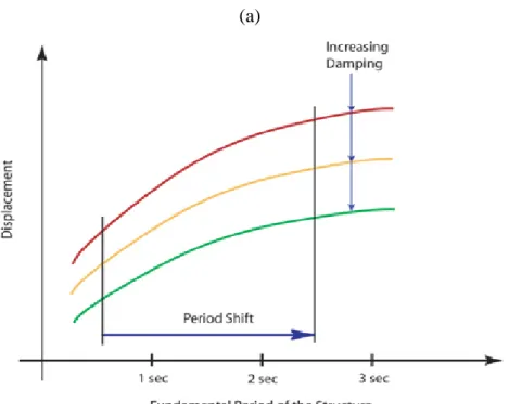
The dynamic response of a seismic-isolated structure depends mainly on its mechanical characteristics (including those of the isolators) and the nature of the ground motion. The fundamental period of the overall isolated structure is increased as a consequence of the isolators flexibility: generally the resulting value is larger than 2 seconds. In principle shifting this period it is possible to avoid the strongest accelerations of an earthquake, as it is shown in Fig. 1 (a).
(a)
(b)
Figure 1 - Isolation characteristics
As a consequence, the earthquake energy transmitted to the structure decreases considerably. Moreover the addition of damping (ranging from 10 to 20 %) allows to reduce the displacements and forces in the superstructure of about 50 %, absorbing some of the earthquake energy, Fig. 1 (b) [2].
The isolators are able to carry the vertical loads of the structure, being laterally flexible elements. In fact their vertical stiffness does not influence the vertical seismic response; it allows to provide vertical load capacity preventing the lateral bulge of rubber layers while allowing the isolator to shear freely.
3. Isolated Plant Configuration
Once the external event has been identified, the NPP dynamic response can be determined adopting a deterministic methodology by means of suitable numerical analyses.
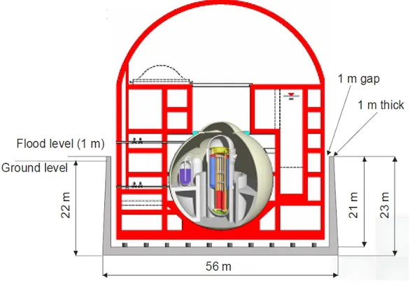
In this study a modular and integral SMR, with reference, as an example, to the IRIS project [4], has been considered. In the IRIS reactor the adoption of seismic isolation devices under the containment building foundation (Fig. 2) would practically reduce the propagation of the ground motion acceleration up to the reactor vessel and the inner containment structures.
Figure 2 - Scheme of the IRSI isolation system
Among the various isolation systems high damping rubber bearings (HDRBs) were chosen in this analysis to isolate the IRIS reactor includes, as they are the worldwide most diffused and reliable isolating devices.
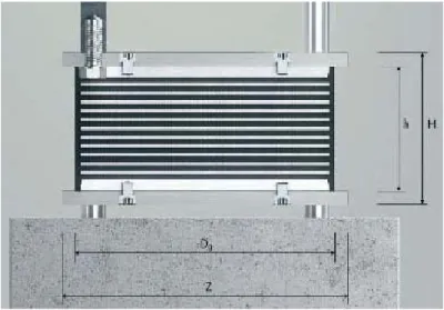
The high damping rubber bearing, shown in Fig. 3, supports the structure and reduces, in the same time, the forces transmitted up to the structure by absorbing and dissipating, through the rubber hysteretic damping, the energy of the earthquake [5]. Moreover HDRBs are made with a
rubber type material having high damping properties and a shear modulus (G) ranging from 0.8 to 1.4 MPa.
Accordingly to the requirements of ASCE 43-05, the isolation devices shall not suffer damage
under the design basis earthquake and sustain the gravity and earthquake-induced loads at 90th
percentile lateral displacements consistent with 150% design level ground motion [6].
Figure 3 - High damping rubber bearing section
Considering that the isolated IRIS reactor building is characterized by a quite low natural frequency along the horizontal direction, where the earthquake has generally quite low energy, and taking into account that the first natural frequency of the IRIS reactor building is about 5.91 Hz, it was decided to adopt 0.7 Hz as isolation frequency for that assessment.
The choice of 0.7 Hz was due to the fact that the lower design displacement of the isolators resulted in a higher safety margin against failure (a factor 3 at least) in case of a severe earthquake.
4. Analysis of an isolated SMR
In this section, the response of a SMR base-isolated reactor building is investigated adopting a deterministic approach and considering the influence of the real isolation bearing characteristics.
The simulation of the plant behaviour was analysed using a validated and reliable finite element method [7] and implementing the real isolator’s material properties and characteristics obtained
from the experimental test series2 carried out on the scaled down prototypic devices HDRB
SI-H 500/50 [8].
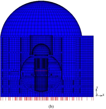
To adequately represent the favourable isolation effects on the considered nuclear plant, a rather refined three-dimensional model (FEM approach) of the SMR reactor containment and its safety relevant structures (Fig. 4) was set up and used in the performed preliminary analyses, taking also into account suitable behaviour and constitutive laws for both the reactor and the isolators materials. The location of the HDRBs in the model is indicated in Fig. 4 with the red lines.
(b)
Figure 4 - Isolated RB model: view (a) and section (b)
Moreover to obtain a suitable three-dimensional base isolation system, a combination of base horizontal and vertical isolation components was considered into the isolated RB model in order to attain a rather significant positive effect in decreasing the dynamic response in terms of accelerations of all RB SSCs, limiting at the same time the horizontal maximum relative displacement between the ground and the RB structure.
In this way, due to high horizontal flexibility of the isolators, which are strained in shear (carrying at the same time the system dead load), the seismic motion may be reduced of a factor 2 or 3.
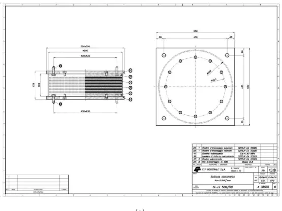
plates providing the necessary vertical stiffness and 128 overall height, like that showed in Fig. 5 (a) and (b).
(a)
(b)
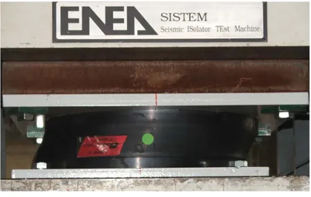
Figure 5 - HDRB SI-H 500/50 tested prototype views
Scope of the carried out tests was to verify the variation of horizontal stiffness and relevant damping while the shear strain amplitude changes. Three sinusoidal cycles, at the design
frequency of 0,7 Hz, have been applied at ±5%, ±10%, ±20%, ±50%, ±100% and ±150% of the shear strain on each device [8].
The obtained experimental data allowed to determine the stiffness and damping characteristics that were implemented through the spring-dashpot system approach in the isolated RB model. The horizontal stiffness has been obtained from the sinusoidal tests in the time domain, whilst the vertical one from the compression tests. The behaviours of force vs. displacement used to determine both the horizontal and vertical stiffness are showed in Fig. 6 (a) and 6 (b), respectively. -250 -200 -150 -100 -50 0 50 100 150 200 250 -60 -50 -40 -30 -20 -10 0 10 20 30 40 50 60 Displacement (mm) For c e ( K N ) (a) 30000 40000 50000 o a d ( K N )
Figure 6 – Force vs. displacement behaviours
The damping properties were observed in the range from 10% to 20%; but in the performed safety-oriented analyses the isolator damping was assumed equal to 10%.
The experimental tests on the scaled down HDRB prototypical devices, of which some phases are shown in Fig. 7, were repeated up to 300% shear strain (Fig. 7 b). The obtained results highlighted that up to 150 mm of displacement, corresponding to about 300% shear strain, the device did not show any sign of damage (Fig. 8).
(a)
(b)
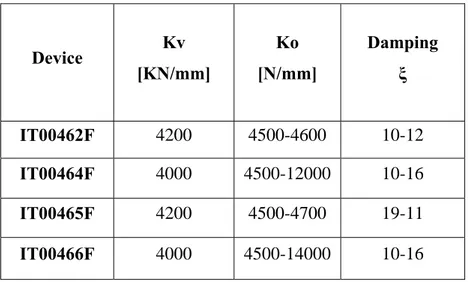
Table 1 – Test results of the HDRB scaled prototypical devices
Device Frequency range
[Hz] Shear strain (%)
IT00462F 0.1-1.5 100
IT00464F 0.5 5-150
IT00465F 0.1-1.5 100
IT00466F 0.5 5-150
Table 2 – Test results of the HDRB scaled prototypic devices
Device Kv [KN/mm] Ko [N/mm] Damping ξ IT00462F 4200 4500-4600 10-12 IT00464F 4000 4500-12000 10-16 IT00465F 4200 4500-4700 19-11 IT00466F 4000 4500-14000 10-16
After having adequately modelled the main structures in the RB model, non-linear analysis was performed applying the acceleration time history approach.
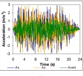
The input motion, applied in form of acceleration time history (all the three acceleration components in the three mutually orthogonal directions), was derived according to the Regulatory Guide US NRC 1.60 and compatible with the given free-field spectra, with a maximum peak ground acceleration (PGA) equal to 0.3 g applied at the base of the nuclear basement (Fig. 9 (a) and (b)).
-3 -2 -1 0 1 2 3 0 4 8 12 16 20 24 Time (s) A c cel e rat io n ( m /s 2 ) Ax Az Avert (a) 0,0 0,2 0,4 0,6 0,8 1,0 0 1 10 100 Frequency (Hz) A c cel e rat io n ( g ) Ax Az Avert (b)
5. Numerical Results
Before analyzing the response of the considered nuclear plant, the modal analysis has been carried out in order to verify the correct scaling up of the isolator properties.
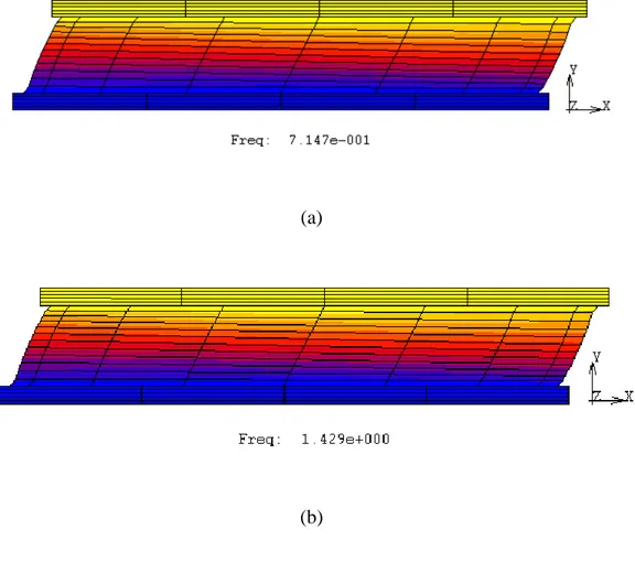
Accordingly to the scaling theory the frequency of a scaled down isolator devices is proportional to the scaling factor, as indicated in the following Fig. 10, which shows the first frequencies of the HDRB in real dimension and in the scaled down one (scale factor 1:2).
(a)
(b)
Figure 10 - 1st frequency of two HDRBs in real (a) and scaled (b) dimensions
After having verified that the adequacy of the adopted methodology, non-linear transient analyses were performed on the RB structure subjected to the assumed SSE motion.
The dynamic response of the isolated plant and the effectiveness of the isolation system were evaluated by analysing the obtained accelerations and displacements at different locations
and/or elevations, as for instance in correspondence of the RPV skirt restraints or at the RB roof.
Furthermore the results were compared with those obtained for the not isolated structure for highlighting and confirming, as foreseen and already mentioned, the positive influence of the isolation approach in siting with a seismic risk.
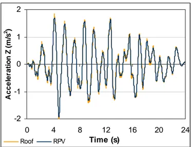
Overviews of the calculated accelerations and displacements behaviours are shown in the following Figs. 11, 12 and 13.
The obtained results in terms of accelerations highlighted the positive foreseen effects of isolation system in mitigating the propagation of both SSE horizontal acceleration components, which decreased of about 30 %.
-3 -2 -1 0 1 2 3 0 4 8 12 16 20 24 Time (s) A c cel er at io n X ( m /s 2 ) Roof RPV 2 4 Y ( m /s 2 )
-2 -1 0 1 2 0 4 8 12 16 20 24 Time (s) Accel era ti o n Z ( m /s 2 ) Roof RPV
Figure 11 – Acceleration behaviours at different elevations in isolated RB
As for the vertical component of acceleration is concerned, it is worth underlining that this component remains almost still unchanged up to the RPV skirt restraints, while generally it results amplified along the RB height.
On the other hand the acceleration values (Fig. 12 (a) and (b)) obtained analyzing the dynamic structural response of the not isolated RB structure, subjected to the same SSE, highlighted an amplification of the accelerations along the height of RB itself, especially at the highest floors, which reached values of about 2 times higher than the earthquake PGA due to the overall containment building flexibility.
-8 -4 0 4 8 0 4 8 12 16 20 24 Time (s) A ccel er at io n A x ( m /s 2 ) Roof RPV Foundation
-3 -1 1 3 0 4 8 12 16 20 24 Time (s) A ccel e rat io n A y ( m /s 2 ) Roof RPV Foundation -8 -4 0 4 8 0 4 8 12 16 20 24 Time (s) A c c e le ra ti o n A z ( m /s 2 ) Roof RPV Foundation
Figure 12 – Accelerations behaviours at different elevations in not isolated RB
ground motion (accordingly to the carried out experimental tests the considered isolators
allowed about 300 % shear strain before the rupture).
-0,10 -0,05 0,00 0,05 0,10 0 4 8 12 16 20 24 Time (s) R e la ti v e D x ( m ) Roof RPV -1,0E-03 -5,0E-04 0,0E+00 5,0E-04 1,0E-03 0 4 8 12 16 20 24 Time (s) R e la ti v e D y (m ) Roof RPV
-0,10 -0,05 0,00 0,05 0,10 0 4 8 12 16 20 24 Time (s) Re la ti v e Dz ( m ) RPV Roof
Figure 13 – Displacements behaviours at different elevations in isolated RB
Moreover, as a confirmation of the good performances of the adopted isolation devices, it is worth noting that the obtained results, in terms of both horizontal accelerations and displacements, are “similar” inside and along the isolated RB structure height, as foreseen, due to its mentioned almost “rigid” behaviour.
Finally the floor response spectra (FRS) were calculated into the frequency domain: the horizontal components of the input motion were reduced up to 30 % as shown in Fig. 14.
0,4 0,6 0,8 1,0 e le ra ti o n (g )
The calculated FRS indicates and confirms the favourable effects of the implemented isolation bearings as well as the capability of the seismic isolation technique to increase the safety margin of the nuclear facility (Fig. 15).
0,0 0,5 1,0 1,5 0 1 10 100 Frequency (Hz) A c c e le ra ti on (g)
Not isolated Ax Not isolated Az Not isolated Avert Isolated Ax Isolated Avert Isolated Az
6. Conclusions
A preliminary evaluation of the safety margin of an innovative SMR (e.g. the IRIS one in the performed analyses) subjected to a severe seismic event (having PGA equal to 0.3 g) was carried out, using the Time History approach and considering the adoption of the seismic isolation.
The strength assessment of the isolated RB structure required considerations not only on the available geometry and material behaviour of the most important SCCs, but also on the characteristics of the seismic isolation type and of the rubber bearing itself.
To the purpose of this study the real behaviour and characteristics of the HDRBs (damping, stiffness, etc.), like the ones obtained from a rather extensive experimental test campaign on scaled down HDRB prototypic devices, were implemented in a quite refined RB FEM model. The comparison of the obtained results with those of not isolated RB, in terms of acceleration, displacement and response spectra, highlighted the effectiveness of the isolation system, in mitigating the seismic response of the RB and its internal structure, like the RPV (which was not affected by relevant stress value).
The obtained results also confirmed the foreseen favourable effects of the isolators: the horizontal components of the input motion were reduced up to 30 % while the displacement increased as it was foreseen.
Finally the results allowed to check and confirm the consistency of this methodology compared with the simplified one (spring-mass dashpot approach), adopted in the preliminary analyses discussed in a previous document (CIRTEN-UNIPI RL 1058-2010).
The lateral shift of isolators resulted about 10 cm, close to the measured 300 % shear strain; therefore the isolators appeared capable to ensure a higher safety margin against failure (as experimentally confirmed) in the considered accidental conditions.
References
1. NRC, Earthquake Engineering Criteria for Nuclear Power Plants, 10 CFR 50.
2. R. Lo Frano, G. Forasassi, Analysis of Seismic isolation problems of NPP buildings, Proceedings of ENC 2010, Barcelona 2010.
3. V. A. Matsagar and R. S. Jangid, Seismic response of base-isolated structures during impact with adjacent structures, Engineering Structures, 25 (2003) 1311-1323.
4. M. D. Carelli et al., The Design and Safety Features of the IRIS Reactor, Nuclear Engineering and Design, 230, 151-167 (2004).
5. M. Forni et al., Seismic isolation of the IRIS nuclear plant, Proceedings of the PVP2009 Conference, Prague, Czech Republic 2009.
6. ASCE, Seismic Design Criteria for Structures, Systems and Components in Nuclear Facilities, ASCE 43-05, 2005.
7. R. Lo Frano, G. Forasassi, Preliminary seismic analysis of an innovative near term reactor: Methodology and application, Nuclear Engineering and Design, 240 issue 6, 1671-1678, 2010.
8. M. Forni, Guidelines proposal for seismic isolation of Nuclear Power Plant, RdS/2010/86- NNFISS - LP2 - 038, AdP MSE-ENEA, 2010.