2
INTERNATIONAL ORGANISATION FOR STANDARDISATION
ORGANISATION INTERNATIONALE DE NORMALISATION
ISO/IEC JTC1/SC29/WG11
CODING OF MOVING PICTURES AND AUDIO
ISO/IEC JTC1/SC29/WG11 MPEG2015/m35908 February 2015, Geneva, Switzerland
Source Università degli Studi di Brescia Status Input
Title A proposal of conformance tests for CDVS
Author Nicola Adami, Mirko Gagni, Claudia Gargiulo, Stefano Maccarana, Federico Polini, Muhammad Umar Riaz & Riccardo Leonardi.
Abstract
The MPEG-‐7 standard has specified an image description tool designed to enable efficient and interoperable visual search applications, allowing visual content matching in images. Visual content matching includes matching of views of objects, landmarks, and printed documents, while being robust to partial occlusions as well as changes in viewpoint, camera parameters, and lighting conditions. Since this has led to a novel set of specifications of the normative parts for this type of standard, conformance testing requires a new approach. This input document proposes a methodology that is being considered for such a purpose.
1 Introduction
In multimedia compression standards, normative parts are decoder specific so that any compliant bit-‐ stream can be decoded to generate a reconstructed version of the compressed data which, in absence of transmission errors, is identical to the reconstructed version that the encoder has produced. In the specification of MPEG-‐7 part 13 [1], Compact Descriptors for Visual Search, the encoder must select a robust set of key-‐points and associated local features invariant to the presence of scale-‐ and rotation-‐ changes.
Sensitivity to key-‐point selection may lead to significant variations of the local feature computation which in turn may significantly affect the performance of retrieval tasks since both patch matching may be missed and relative geometric consistencies may be difficult to be determined.
To keep the competitive nature of the standard specification conformance becomes an essential part of the validation process. Conformance means in this case that different implementation of the standard should generate from a same image largely overlapping sets of keypoints and that their surrounding feature description should be kept at minimal distances as suggested for existing similar technologies [2].
Accordingly section 2 will described the adopted methodology. This has led to an improvement of the standard text the corresponding suggestion are reported in Annex A.
2 Methodology
We propose to verify conformance of an implementation in 2 stages:
-‐ starting from the standard description text, checkpoints are defined to facilitate that any implementation leads to complying specifications with respect to standard compliant ones;
-‐ In the second stage, a dataset is provided to run validation experiments, the results of which are compared to the performance achieved with the TM
At both levels, if the results fall within a certain margin to be determined by the conformance specifications the proposed implementation will be considered compliant.
For the first stage the following checkpoints of the CDVS encoding specification section 5 in [1] have been selected:
1 at the end of section 5.3.3: detection of local scale-‐space extrema (and associated scales) 2 at the end of subsection 5.3.8: interest points characteristics
3 at the end of subsection 5.5: Local feature description
4 at the end of subsection 5.8: Local feature location compression
For checkpoint 1 to 3, uncompressed values are compared whereas comparison may take place on binary representations of the compressed streams.
The first stage comparison is still on-‐going, so that description comparisons could not be verified at the end of checkpoints 1 through 4.
An independent implementation of the standard is being constructed by CDVS non-‐expert people. In particular no reference was used to the description details provided in TM12 [3]. It has allowed to identify imprecisions in the standard text which we report in Annex A.
References
[1] Information Technology – Multimedia Content Description Interface – Part 13: Compact Descriptors for Visual Search, ISO/IEC FDIS 15938-‐13, output document ISO/IEC JTC1/SC29/WG11/N14956, Strasbourg, Oct. 2014.
[2]
http://www.vlfeat.org/.
[3]
Test Model 12: Compact Descriptor for Visual Search, ISO/IEC JTC1/SC29/WG11/N14961, Oct. 2014, Starsbourg, France.Revision Document – based on w14956_text.doc 4
ANNEX A: Editing suggestions on current standard text
Comments hereafter are proposed separately for each concerned subsection in [1].
5.3.2 Scale space construction
The goal of this part is to load the original image and produce the so-‐called pyramid structure made of elements called “octaves”.
Note:
The filter defined in Formula (3) is useful to understand the underlying principle, but it is not used in the standard CVDS implementation.
)
,
,
(
0
1
0
1
4
1
0
1
0
)
,
,
(
2σ
σ
σ
∗
⋅
⋅
⎥
⎥
⎥
⎦
⎤
⎢
⎢
⎢
⎣
⎡
−
⋅
=
⋅
⋅
g
h
5.3.3 Detection of scale-‐space extrema
The goal of this part is to process information obtained in previous step to produce a set of interest points, called “candidates”, which satisfy certain constraints as described in the document w14956_text.doc.
Comment:
The repeated use of the form “Thereafter, any remaining candidates…” does not facilitate readability.
Typo:
During the elaboration of this chapter has found just a single mistake w.r.t. Formula (21); the computation of second derivative is wrong because:
5.3.4 Coordinate refinement to subpixel precision
Comment:
On pages 14 and 15, it's better to use explicitly the dependence of σ* on x, y coordinates (i.e. (x,y,σ*(x,y)) instead of (x,y,σ*).
5.3.7 Orientation Assignment
For each interesting point candidate the corresponding orientation histogram is obtained as defined in Formula (39) and Formula (40). The original standard text “Dominant orientations shall be determined by locating the peaks in the orientation histogram. The bin corresponding to the highest peak, as well as the bins with a bin value greater than 80% of the highest peak value, are selected as the dominant orientations of the interest point.“ implies that more than one orientation can survive and then more than one feature can be generated for a given candidate. Since the final selection of feature elements does not account for orientation this also implies that it could happen
that an interest point could not be represented at all in the final feature vector, since the maximum number is limited to 250.
Comment:
Instead of keeping all the histogram peaks above the 80%, probably only the maximum should be selected.
5.3.8 Interest point characteristics
Comment:
Since the description just represents a summary of previous processing steps, it should be better to move it in the introduction of Subsection 5.4.
Revision Document – based on w14956_text.doc 6
5.4.2 Local feature selection – Descriptor components
Comment:
It is not clear how information contained in this section can be used. Should it be moved in a “system” section describing binary bit-‐stream syntax specifications?
5.5 Local feature description
Typos:
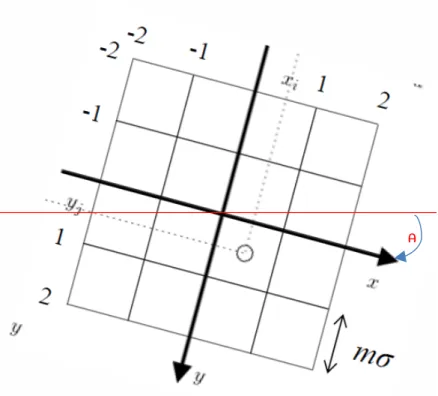
On page 22, in Formula (45) yj should be replaced with yi.
In the same page, G(x,y) in Formula (46) should be replaced with G(x . m. σ*, y.m. σ*).
Comment:
The normalization phase described at the end of Page 22, should be better clarified. For example which scanning order should be used to compose the final (128 bins) histogram? By the way this is really not an histogram but a concatenation of histograms
Comment:
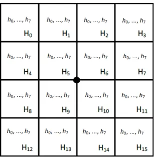
To enhance understandability Figure 6, should be replaced with the following one.
Figure 6 -‐-‐ Local feature descriptor construction
θ
Revision Document – based on w14956_text.doc 8
5.6.1 Operation
Comment:
Formula (50) (
h
t j',=
h
t j,h j
t,
=
0,...,127
) gives a normalized vector by L1 norm which indicates aprobability distribution. However in Formula (51) these values are changed losing the normalization. Is this intentional, if so please describe better all the involved transformation process.
All the processing involved in formulas (53, 54, 55, 56) should be better described. Intermediate steps should be introduced to reduce the complexity of the current description and to ease its software implementation.
In formulas (54, 55, 56) it is not clearly specified what is σi, is. It should be clarified that σi is the
determinant of the diagonal matrix ∑, reported below, obtained placing the values of each row of the variance matrix described in Annex E.
Diagonal matrix for each 32 dimensional row
5.6.2 Descriptor components
Comment:
5.7.1 Operation
Comment:
Figure 8, should be replaced with the following one.
5.7.2 Descriptor components
As in the other cases the Descriptor components part is not related with the other parts of the text and therefore is should be clarified how it can be used.
Revision Document – based on w14956_text.doc 10
5.8.1.1 Operation
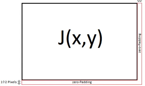
The matrix LB describes 3x3 blocks generated by subdividing the location point matrix. The subdivision in 3x3 is unique only if the number of pixel for the rows and for the columns are a multiple of 3. In the other cases, there is a remainder one or two rows or columns of pixels exist. In these last two cases it should to resolve the ambiguity, for example by applying a zero-‐padding. In Figure 2 a simple suggestion is proposed.
Figure 1. A zero-‐Padding example.
The whole source coding method should be better clarified, adding details and examples on the static and adaptive stages.