Analysis of the Acting Forces in a Theory of
Catalysis and Mechanochemistry
Wolfgang Quapp,
∗,†Josep Maria Bofill,
∗,‡and Jordi Ribas-Ariño
∗,¶Mathematisches Institut, Universität Leipzig, PF 100920, D-04009 Leipzig, Germany, Departament de Química Orgànica, Universitat de Barcelona, and Institut de Química Teòrica i
Computacional, Universitat de Barcelona, (IQTCUB), Martí i Franquès, 1, 08028 Barcelona Spain, and Departament de Ciència de Materials i Química Física, Secció de Química Física
and IQTCUB, Universitat de Barcelona, Martí i Franquès, 1, 08028 Barcelona Spain
E-mail: quapp@uni-leipzig.de; jmbofill@ub.edu; j.ribas@ub.edu
date: March 21, 2017 R2 submitted: J.Phys.Chem.A
Abstract
The theoretical description of a chemical process resulting from the application of mechan-ical or catalytmechan-ical stress to a molecule is performed by the generation of an effective potential energy surface (PES). Changes for minima and saddle points by the stress are described by Newton trajectories (NTs) on the original PES. From the analysis of the acting forces we postulate the existence of pulling corridors build by families of NTs which connect the same stationary points. For different exit saddles of different height we discuss the corresponding pulling corridors; mainly by simple two-dimensional surfaces models. If there are different exit saddles then there can exist saddles of index two, at least, in between. Then the case that
∗To whom correspondence should be addressed †Leipzig University
‡Universitat de Barcelona ¶Universitat de Barcelona
a full pulling corridor crosses a saddle of index two, is the normal case. It leads to an intrinsic hysteresis of such pullings for the forward or the backward reaction. Assuming such relations we can explain some results in the literature. A new finding is the existence of roundabout corridors which can switch between different saddle points by a reversion of the direction. The findings concern the mechanochemistry of molecular systems under a mechanical load as well as the electrostatic force and can be extended to catalytic and enzymatic accelerated reactions. The basic and ground ansatz includes both kinds of forces in a natural way without an extra modification.
1
INTRODUCTION
The application of mechanical stress to molecular systems has recently attracted significant interest as a means of controlling chemical reactions. Under stress the minimums and saddle points (SP) of the potential energy surface (PES) change their relations. This concerns the energy height as well as the molecular geometry. Curves for such changes in the configuration space of a molecule are the aim of this paper. In theoretical chemistry a basic concept already exists underlying many widely used models, namely, the reaction path (RP). The RP is a one-dimensional description of a chemical reaction through a sequence of molecular geometries in an N-dimensional configuration space. A reaction mechanism is described through the PES model by means of RPs. We use N = 3n − 6 for the number of non-redundant internal coordinates, r, and n is the number of the atoms of the molecular system. Such a simplified one-dimensional description generally makes it possible to move on the PES. A well known type of RP models is the Newton trajectory (NT).1–8
For this type of RP holds that at every point of the curve the gradient of the PES points into the same direction, a direction of a prescribed search vector. On the other hand, this property is the central idea of models of mechanochemical stress applied to a molecular system where the search direction is now the direction of the stress vector. This is the reason why NTs should be taken into account as the basic models of a great variety of mechanochemical problems.9 The present study
In the last years, the phenomena of the action of a mechanical stress over a molecular system have motivated experimental and theoretical researches (see Refs. 12–23 and references therein) We will here quantify molecular stress geometrically. Basically, the model employed to rationalize mechanochemical experiments was created early by Eyring et al.,24 by Bell25 in 1978, and it was
used, for example by Bustamante et al.26 in 2004. More recently, it was recreated and treated by
Ong et al.,27 by Ribas-Ariño et al.28 and by Wolinski and Baker29 in the same year 2009. The
generally accepted model15,19,30 consists in a first order perturbation on the associated PES of the
unperturbed molecular system, V (r), due to a stress or pulling force vector, f, by
Vf(r) = V (r) − fT · (r − ro) , (1)
where the symbol T means transposition of a vector or a matrix. r is the coordinate vector, ro is
any fixpoint, and f is the force vector. In this equation, being the starting point for the theory of mechanochemistry, the scalar product ∑Ni fi(ri− roi) with the force vector, f, ensures that only the
part of the coordinate vector, (r − ro), in the direction of f acts. The subtrahend in the equation is
a hyperplane in the space IRN+1whith slope in the direction of the force, f ∈ IRN. Vf is named the
force-transformed PES,15,28,31,32or the effective PES. The displacement of the stationary points of
the new effective PES is described by NTs.9–11 The force, f, can be a pull or a push. It is worth
mentioning that a similar model was discussed by Thornton33 for the prediction of the effect of
substituent changes on the transition state (TS) geometry.
The formalism employed to study mechanochemistry can also be applied to explore how ex-ternal electric fields can catalyze and control reactions34–36when these fields are constant in time
and position.34 One could even think of using this formalism as a first-order approximation to
study catalytic and enzymatic processes. Notice that in the present model, the direction and the magnitude of f are constant. (Note that also non-constant forces are studied in the past.37–39) The
used constant force here is certainly a strong approximation, but it might be useful when it comes to understand and design catalysts and enzymes. In this case, the direction and the magnitude of
vector f are fixed for every special catalyst. Indeed, if we can quantify all the electrostatic and non-electrostatic parts of the action of a catalyst (an enzyme in biochemistry), into a force represented mathematically by a vector,f, then we can handle the change of the PES by the ansatz of Eq. (1). The action of the catalyst will then be explicitly calculable and interpretable by the displacement of a TS and a reactant minimum of the original PES, V(r), to the effective PES, Vf(r).
In the present context it is important to consider that historically the problem of enzyme catal-ysis was discussed early by Haldane40 and Pauling.41 There should be an ’active region of the
surface of the enzyme which is closely complementary in structure not to the substrate molecule itself, ..., but rather to the substrate molecule in a strained configuration...’, meaning the transition state (TS). ’... and caused by the forces of attraction to assume the strained state which favors the chemical reaction...’41 Thus Pauling proposed that the enzyme binds the TS. It was named TS
stabilization (TSS), in contrast to reactant destabilization.42–44 The activation energy is lowered
for the catalyzed versus the uncatalyzed process, giving rise to large rate accelerations. It is equiv-alent to the action of Eq. (1) for pulling which leads us to the remark that this equation not only describes the pulling process, but can generally describe catalysis as well.10,11,26
A second look back has to appreciate the early guess of Warshel42,45–47 that the catalytic effect
of enzymes has an electrostatic origin. An electrostatic force of the enzyme stabilizes the TS of the accelerated reaction: this expresses in words what Eq. (1) expresses as a linear ansatz by a formula. Maybe this ansatz is too simple for a given problem, but it explains many observed and studied results and now remains the task to determinate the force, f, for every enzyme. The methodology reported in the next section allows us to calculate explicitly the lowering of the activation energy by the enzyme, if f is known (and if we can calculate, or approximate the PES, or the free energy surface of the reaction under consideration).
At this point, it should be mentioned that mechanochemistry and catalysis should not be con-sidered as two different facets of chemistry under the point of view of Eq. (1). Indeed, a direct combination of electrostatical and mechanical forces is found in molecular motors. These two facets also meet in the research area of mechanical activation of catalysts48,49 and on experiments
in which an enzyme acts on a substrate subject to tensile stress.50,51
In this article, we present the chemical consequences of a topological study of generic PESs based on NTs that are related with the basic ansatz Eq.(1). For this reason, the conclusions drawn are completely general, independent of the type of quantum mechanical calculation of the PES. Nevertheless, chemical examples from the literature are discussed under this new view corrobo-rating the present theory. Our analysis demonstrates the existence of streams of NTs (which will be referred to as chemical corridors) that are crucial to understand and model the acting forces in mechanochemistry and catalytic phenomena. We will unveil the unforeseen challenges and com-plexity embodied in Eq. (1). The article is organized as follows. Next we explain the theory of NTs for the understanding of a chemical pulling/pushing process, or an action of a catalyst (enzyme). This theoretical part is a summary of that published in references 9,10, and is briefly exposed and explained, in this way the article is self-contained. Then we use two-dimensional test surfaces to explain the impact of stress on the topography and the stationary points of the effective PES. We mainly treat the ’strong multidimensional case’22with competing reaction pathways. We show that
already for two dimensions, if at least two competing RPs exist, we can find rather complicated areas for the movement of the stationary points on the PES under stress. Nevertheless, though pure theoretical, these generic surfaces are taken from well tested models of specific chemical systems. The paper presents at the end a Discussion, and some Remarks with a Conclusion.
2
METHODOLOGY
For a given force, f, we have an effective PES, Vf(r), which has a new inherent chemistry with
respect to the unperturbed PES, V (r), such as other reaction rates and other chemical properties. Of course, the linear perturbation in Eq. (1) is the simplest model.52Meanwhile, time was used to
derive new basic ideas of mechanochemistry.15,52–57 The force f in Eq. (1) may be determined by
the change of a distance between two pulling points of the molecule,58or by any other experimental
combination of them.27 Throughout the present work we assume for simplicity that the plane
of two intrinsic coordinates (x, y) is the stage where the pulling works. These coordinates may describe the weakest point of a molecule where it breaks preferentially.59 We note that the theory
and the use of NTs can be applied to N-dimensional systems with any large n for the number of included atoms.
Due to the external force, the stationary points are located at different positions on the effective potential, Vf(r),56with respect to the unperturbed potential, V (r), where it holds ∇rV(r) = g(r) =
0. g(r) is the gradient of the unperturbed PES. The stationary points on the effective potential have to satisfy the analogous condition, ∇rVf(r) = 0. Since Vf(r) is the one given in Eq. (1) there
follows that the new minimums or SPs should satisfy
∇rVf(r) = 0 = g − f . (2)
One searches a point where the gradient of the unperturbed PES, g, has to be equal to the mechano-chemical force, f, being the force that induces the mechano-chemical process. If the mechanical stress in a defined direction is f = Fl with a fixed unit vector, l, then it is l = g/|g| and F = |g| is the mag-nitude at the stationary points since from Eq. (2) we have, 0 = l (|g| − F), being satisfied if the former equality is also satisfied. Eq. (2) means that the tangential hyperplane to the original PES, characterized by the gradient, g, is equal to the hyperplane of the pulling force, fTr, in Eq. (1). The
case F = 0 is named the pure thermal limit.15This is the case without a mechanical load.
Now we treat a fixed direction of l, but different magnitudes of the forces, F. For changing magnitudes, F, we get a series of effective PESs (1), and on every effective PES we get its sta-tionary points. So we get a path following for the curve of the force displaced stasta-tionary points (FDSPs).30 The minimums and the SPs of any index of the effective PES (1) change and they are
on the FDSPs curve, because at these points holds ±|g| = F. A FDSPs is the path connecting the stationary states of the perturbed PESs. Each effective PES of this ensemble corresponds to a given
magnitude F of the force but to the same direction l of application.
The FDSPs are on the solution of the differential equation of Branin60 which we can use in
N= 3n − 6 nonredundant coordinates9,10
dr
dt = ±A(r) g(r) . (3)
t is a curve parameter and the matrix A is constructed as a product of the determinant of the Hessian, H, of the unperturbed PES with the inverse Hessian,
A = Det(H) H−1. (4)
At the given g, the Branin equation yields a “Newton Trajectory” (NT) corresponding to the FDSPs for this g. The Branin equation is nothing but a simple strategy to generate the points on the FDSPs without solving g/|g| = l and ±|g| = F for several values of the force magnitude.
The signs ’±’ in Eq. (3) are used to allow the curve to go uphill from a minimum, or downhill from an SP. Curves r(t) satisfying this expression are called Newton trajectories (NT). A property of Eq. (3) is that the gradient at every curve point always points into the same direction, l, if it had this direction at an initial point. Then holds the parallelity of the vectors, l||g, throughout the path.1,2 Note that different directions l cause a spread of NTs, as it will appear in the various
examples later in the paper.
The solution curve of the Branin equation is a regular curve from a point near the minimum to an SP if no valley-ridge inflection (VRI) point is crossed.2However, if this curve crosses in its
evolution a VRI point, then this NT curve is named a singular NT. It bifurcates at the VRI. A VRI point is a region on the PES where the curvature orthogonal to the gradient becomes zero. There usually a valley or a ridge bifurcate.2,61 The Branin Eq. (3) is a well-known model for RPs.1,2,5,8
This RP model is especially used here for the FDSPs: for every special magnitude of the force, F, we get a moved stationary point of the new effective potential, Vf(r) with f = Fl and g = l|g|, but
pulling direction. The reason is that this special pulling direction does not change the description of this special NT on every effective PES under the pulling.
Note that the NT which describes the curve of FDSPs is not used here for a reaction path. Nevertheless, the effective stationary points of Vf(r) of Eq. (1) can be connected by a chemical
reaction path to describe the usual reaction process over the effective SP. That can be an NT, or the IRC,62 or any other definition. That path is named ”mechanical coordinate”26 but we do not treat
it here.
If one moves on the path of FDSPs one moves, so to say, from one force displaced effective PES to the next. Step by step one has to increase the norm of the force, F, beginning at the original stationary points with F = 0 in the thermal limit: there is a part of the pathway from the minimum uphill, and a part leading usually downhill from the SP. If the force increases further and further, the two parts of the FDSPs have to meet. Here the norm of the gradient has its maximum. The NT goes through a shoulder on the effective PES. The curvature of the PES along the corresponding NT is zero, because at the meeting point of the effective minimum and the effective SP we have dVf(r)/dt = lTAl(|g| − F)|g| = 0. As a consequence, the barrier of the
original PES disappears here. In other words, on the effective PES, Vf(r), with the maximal
rupture force,63 the SP disappears, and the pulling force realizes the reaction. (This may happen
somewhat earlier because of the existence of the zero point energy at the former minimum.) We propose to name the point the barrier breakdown point (BBP). Its necessary mathematical formula is10,64
Det(H) = 0 . (5)
Note that H is always the Hessian of the original zero-force PES, V (r), because the model Eq. (1) and Eq. (2) do not influence the calculation of the Hessian33 (the first order perturbation in ansatz
(1) does not change the second derivatives of the PES because f is constant and consequently inde-pendent of r, differentiating Eq. (1) two times with respect to r we have ∇r∇TrVf(r) = ∇r∇TrV(r) = H (r), thus the Hessian coincides for both PESs). The idea of the proof of condition Eq. (5) is that
the BBP is a turning point of the function |g| along the NT. A proof of Eq. (5) is given in Ref. 10. The definition of an optimal pulling direction10 is also derived: the mechanical force to be applied
to the molecule of interest is f = F l where F =pgTg. To each NT belongs the corresponding
l-vector, and by varying it we have different NT curves. All the regular NTs, that leave the minimum and arrive at the same SP, cross at least once a Det(H) = 0-line. The Det(H) = 0-line that each NT crosses gives the BBP of this NT, the maximal rupture force, Fmax. This is due to the fact that at the
BBP point of a regular NT, the gradient norm |g|, takes its maximum value along this NT curve. If we compare all NTs of such a set, then the NT which gives the lowest value of Fmax is named
the optimal NT. It coincides with a gradient extremal (GE) exactly at the intersection point with the Det(H) = 0-line.10 In this special BBP, the Det(H) = 0-line, the GE and the optimal regular
NT meet. The optimal BBP is a stationary point on the function |g| crossed by the optimal NT. On higher dimensional PESs, the condition Det(H) = 0 may describe a manifold. So, the definition of optimality works in any dimension.
Min Min VRI VRI SP -2 0 2 4 -1.5 -1.0 -0.5 0.0 0.5 1.0 1.5 x y
Figure 1: Direct chemical corridor of type 1 of the PES of Eq.(S1) in SI. All the regular NTs between the two singular NTs (in blue and orange color) form this corridor. Some regular NTs (in gray) are shown. The BBP condition, Det(H) = 0, is the green line. A singular NT is the Newton trajectory that passes through a VRI point, whereas a regular NT does not pass through this type of points. The spreading of pulling directions can be large.65 All NTs describe pulling directions to different families of effective PESs. The surface without load is shown in the background for comparison.
the corresponding magnitude Fmax was the rupture force. BBPs for bonds in diatomic molecules
are calculated,15,66,67 as well as the BBPs for single bonds in some polyatomics.66,67 The
one-dimensional BBP-problem is treated by Freund as well.68 With the present model, both the BBP
and Fmax can be predicted for large molecules, thus in a higher dimension. From a mathematical
point of view the BBP concept is strongly related with the Catastrophe Theory.69–71From this view
BBP represents a catastrophe of the PES function being unfolded by a force affecting through the additional perturbation term, fT(r − r0), of Eq. (1).10 This gives us the general structure of all
possible effective PESs with zero eigenvalue at this point. For this reason this mathematical model can be used to predict mechanochemistry mechanisms and catalysis. In the present study we will use corridors of NTs on test surfaces to treat regions of the PES where all NTs lead to the same stationary point. A pulling, or correspondingly a pushing along every of these NTs enforces the same type of FDSPs on the PES. We name such a common set of NTs a corridor, however, due to the physical-chemistry significance of this set of curves, we call it a chemical corridor. Of course, the BBPs of the NTs of a corridor can be very different in their energy height, as well as in their bond breaking gradient force.10,11
3
MODELS FOR CHEMICAL CORRIDORS
The theory herein presented aims to rationalize both mechanochemistry and catalysis. It is based on the topology or, more specifically, the topography of the common PES associated to different types of chemical mechanisms. In the following, we shall analyze the topography of the basic PES models, namely, (i) a PES describing an elementary pathway, (ii) a PES describing a process with two different reaction channels, and (iii) a PES describing a process with two different reaction channels that include intermediates. This will permit us to draw generic topological conclusions which are important for the general applicability of the present theory.
3.1
Potential energy surface with an elementary pathway
We present as an example a simple PES with a one-step mechanism to analyze the nature of the corridors associated to this type of PES. As a generic representative of this class of PES, we use the skew double-minimum PES,6,10whose mathematical description is given in the Supplementary
Information (by Eq.(S1), the PES is shown in Figure 1). This PES has two minima, connected by one SP of index one (i.e, a transition state).
In Figure 1 the direct corridor between the two minima is represented by NTs. This kind of corridor is named of type 1. The green line is the BBP-condition Det(H) = 0. The dashed line is the convexity border of the PES given by gT A g = 0.72 The ridge and valley regions of the PES
are separated by this line. Shown are the two singular NTs of the PES by blue and orange color. They bifurcate at two VRI points. They are the two border lines of the corridor. Thus a chemical corridor of type 1 is characterized by the set of regular NTs joining two minimums of the PES related with reactant and product. It goes through an SP of index 1 in between, and it is limited by singular NTs. Not all regular NTs of this corridor satisfy the reaction path requirement to rise up without a turning point (TP), but a subset of NTs do so. The regular NTs that belong to this subset are reaction pathways satisfying the condition of the minimum energy path.73 The gradient
norm at the BBP line is the maximal force at which a reaction is enforced.26,65 Going along an RP
the gradient norm achieves the maximum value at the intersection point with the BBP line.10 Of
course, the maximal force significantly depends on the pulling direction.
The movement of the effective SPe f f is manifested in many enzymatic reactions.26,74 It was
named stress-induced catalysis by the enzyme, in former treatments. However, we should note that inasmuch as the model of Eq. (1) fits to a reaction problem, the Mine f f moves also along the
pulling NT. The two stationary points both move to come together at the BBP, at least. Depending on the PES, the BBP can be nearer to the original SP (late BBP or TSS) or to the original Min (early BBP).10
N O NO2 H3CO (R)-Spiropyrane H3CO N O NO2 H3CO (S)-Spiropyrane H3CO N NO2 O H3CO (Z)-Merocyanine H3CO N NO2 O H3CO (Z)-Merocyanine H3CO N O NO2 H3CO H3CO δ δ δ N O NO 2 H3CO H3CO N NO2 O H3CO H3CO (R)-BBP2 (S)-BBP2 (R)-BBP1 (S)-BBP1 δ
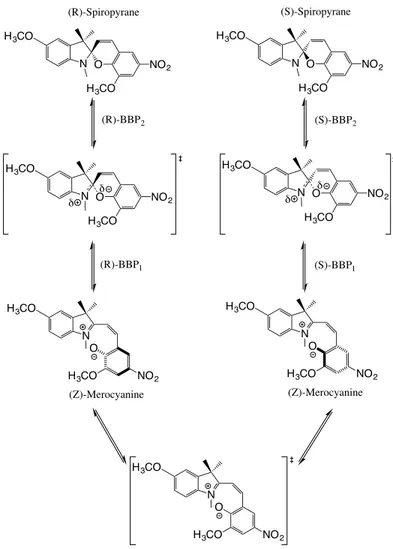
Figure 2: Schematic transformation of (Z)-Merocyanine to Spiropyrane. Depending on the con-formational isomer of (Z)-Merocyanine, an enantiomer of Spiropyrane is obtained. The conforma-tional interconversion of (Z)-Merocyanine takes place through a planar transition state indicated at the bottom.
Starting a pulling at the minimum at the point (-1,-1) in Figure 1, we may observe that the spreading of the tangent directions of the possible regular NTs is large. In contrast, starting a pulling at the minimum at (1,1) in contrary directions, we can observe that the spreading of the tangent directions of the possible NTs is quite smaller. We recall that any NT of the corridor follows one and the same gradient direction through its evolution. Thus both starting points at the minimums encircle an equal range of gradient directions. This also happens at the common SP of index 1 which all NTs cross. From a chemical point of view, this topological conclusion means that if a given vectorial force is able to drive the system from reactants to products in a corridor of
ΦP* ΦP ΦCT ΦCT* TS Reaction Coordinate O...C E C N H O no π π* ΦCT no pn pc C=N C=N ΦP* C-N C-N BBP1 BBP2 -FO-C a) b) c) (Z)-Merocyanine Spiropyrane C NH O O O C N H O
Figure 3: Transformation of (Z)-Merocyanine to Spiropyrane. a) Valence bond correlation diagram for the intramolecular reaction between the nucleophile −O− and the electrophile > C = N+<. b) The charge transfer, ΦCT, and product, ΦP, valence-bond configurations projected from the
molecular orbitals wave function for the −O− attack of a > C = N+< bond. c) The bond breaking point BBP1labeled according Figure 2. BBP1has the major contribution of ΦCT, more than BBP2.
Shown is the external electric field, −FO−C, along the “reaction coordinate" (O · · · C).
type 1, the reverse force will necessarily drive the system from products to reactants.
An example of this type of corridor within the context of mechanochemistry concerns the intramolecular addition of an electrophile to a nucleophile, such as the rearrangement of (Z)-Merocyanine to Spiropyrane, see Figure 2. Each of the elementary pathways of Figure 2 (either the left-handside one or the right-handside one) corresponds to a type 1 corridor.In this particular example, we will consider that the PES is perturbed by an electric field rather than a mechanical force.
TS cpd-Li TS cpd cpd cpd V reaction coordinate 25.4 17.3 a) b)
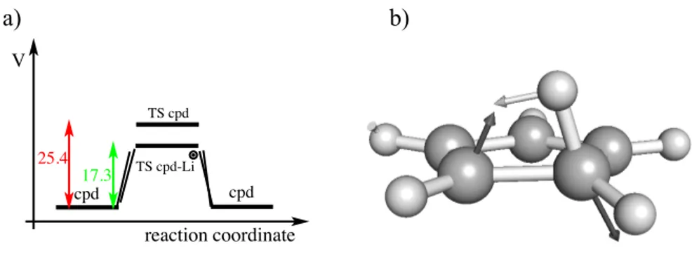
Figure 4: (a) Energy profile of the 1,2-sigmatropic H-shift rearrangement of cyclopentadiene with-out and with Li+ as a catalyst. The energies which are given in kcal mol−1 were computed at the MP2/6-31G* level of theory. (b) The BBP structure obtained from the IRC calculation. The arrows correspond to the components of the gradient vector at this point.
barrier formation and the TS electronic character. The rearrangement corresponds to a nucleophilic addition of the nucleophile −O−to an electrophile being an unsaturated group, > C = N+<, where
N is more electronegative than C.75 The diagram involves two principal curves, which represent
the (Z)-Merocyanine and the Spiropyrane states, ΦCT and ΦP, respectively. Note that the
(Z)-Merocyanine state is charge transfer in nature. This charge transfer involves a single electron transfer from the nucleophile −O− to the electrophile group, > C = N+<. The strongest mixing
happens in the TS region, located at the crossing point between the electronic states. In panel (b) of Figure 3 is shown the charge transfer, ΦCT, and product, ΦP, valence-bond configurations which
are projected from the molecular orbitals wave function for the −O−attack of a > C = N+< bond.
It is important to take into account that the ΦCT state has a major contribution in the description of
the electronic structure of BBP1, shown in panel (c) of Figure 3, in comparison to BBP2.
Let us deeper consider Figure 3 (a). When an external electric field is applied along the “re-action coordinate” C · · · O, a negative FO−Cfield stabilizes ΦCT, which shifts the TS towards the
BBP2. Additionally, this stabilization of the ΦCT state destabilizes the Spiropyrane resulting in
a structural and energetic shift towards BBP2. The vector field, −FO−C, has the direction of the
normalized gradient vector, l2of the BBP2 being the optimal direction for pulling. Increasing the
BBP. The opposite effect for a positive vector field, FO−C, has the direction of the normalized
gra-dient l1of the BBP1. It is again optimal for pushing. It destabilizes the charge transfer state, ΦCT,
which shifts the TS and the (Z)-Merocyanine toward BBP2. As in the previous case, increasing the
magnitude of the force, the TS and (Z)-Merocyanine coalesce to this BBP. The effect of the external electric field on the ΦCT electronic state accounts for finding the normalized direction, either, l1or
l2, which is privileged for the catalysis of this nucleophilic addition to an unsaturated electrophile
group. In the present case both directions coincide with the reaction coordinate C · · · O. This is the direction along which the electrons are reorganized to make the new bond, and this can either be assisted or inhibited by the external electric field. Paraphrasing Shaik,36,76an external electric field
oriented along the direction of the gradient vector of the BBP, that is l being the direction along which the bond changes occur, causes catalysis/inhibition of the reaction process by preferential lowering/raising the transition state and the reactant, depending if the relative direction of the field to the electronic flow that takes place through the l-direction.
An example of another type 1 corridor applied to catalysis is provided by the 1,2-sigmatropic H-shift rearrangement of cyclopentadiene. This reaction was computationally studied by Schleyer77
and it was found that Li+ was able to catalyze it. We take this reaction as an example of the
present model. This chemical example is also proposed as a description of a primitive version of an algorithm based on Eq. (1) to find the optimal catalyst for a specific reaction. The first step consists to locate BBPs on the IRC path joining the reactants and products through the transition state. Since we are going from the reactant to the product we are only interested in the BBP located in the reactant valley. Note that according to the section Methodology this BBP usually is not exactly the optimal, however, it may be close to the optimal one. In the second step we compute and analyze the BBP gradient vector. In the next step we look for a chemical species that makes a force to the substrate in the direction to the BBP gradient vector. Note that in this situation, dVe f f(r) /dt ≈ 0, because, |g| − F ≈ 0, as explained in section 2. In our particular
The selected chemical species which partially satisfies the above requirements is the Li+ which
was located below the molecular plane, that is to say in the opposite side where the H-shift takes place. According to the present theory the direction of the gradient vector at BBP in the presence of Li+ should overlap as maximal as possible with the gradient vector of the BBP without the
cation, otherwise, it is not the best catalyst. In the present case these two vectors form an angle of approximately 30◦. We conclude that Li+ is an efficient catalyst but is not the optimal. The
structure of the BBP and the corresponding gradient vector is reported in Figure 4, part (b). The results and conclusions are in line with those reported in Ref. 77.
Min Min VRI VRI SP -2 0 2 4 -1.5 -1.0 -0.5 0.0 0.5 1.0 1.5 x y
Figure 5: Roundabout half-corridor (above) of type 2 and useless half-corridors (below) of the PES of Eq.(S1) in SI. The NTs of the corridor fall apart into two branches. The set of circular branches characterize a chemical corridor for a pulling from the upper minimum to the lower one. The escaping NTs in the lower part indicate that a pulling in one of these directions is useless. None of the branches crosses either the BBP line (green) or the SP of index 1. These directions characterize a useless chemical corridor.
The PES displayed in Figure 1 also contains another type of corridor. In Figure 5 a useful half-corridor for the upper minimum only is represented. It is filled with circular NTs which connect the upper minimum and the SP only and which cross the upper BBP line (the green line). This kind of corridor is named of type 2. Note that again the two singular NTs are the border lines of the corridor.
lower minimum at the point (-1,-1). They cross neither the next BBP line nor the SP of index 1. They characterize a forbidden chemical corridor for a pulling purpose. Note that in this case the pulling is not impossible but useless and leads in every case to an enforced reaction from the upper minimum to the lower one. We call this half-corridor a useless chemical corridor. As an example of this type of corridor, we could mention the failure of external forces to induce isomerizations of double bonds (i.e, E,Z transformations) reported in Refs. 78,79.
4
Potential energy surfaces with alternate pathways
Some chemical reactions take place through competing mechanisms. The topography of the PESs associated to these mechanisms consists in alternative pathways joining one reactant minimum to the same or different product minimums. Between the two SPs of index 1 can be an SP of index two.80–82 The difference between the alternative pathways is given by the barrier height of the
corresponding SPs of index 1 and the possible existence or not-existence of minimums associated to intermediates. The existence or not-existence of intermediates can complicate the topological study of the pulling phenomena according to the basic Eq. (1). For this reason we present two cases in the following separated subsections. The examples analyzed and discussed below can be viewed and understood as topological maps from real chemical systems for pulling scenarios22 where the
high dimension of the problem is projected into two intrinsic and distinguished dimensions. We use such a projection to draw chemical-physical consequences. We start with the simplest case of two parallel reaction pathways without an intermediate.83 This type of surface is relevant for
modeling the so–called catch bonds.84–97
4.1
Alternate elementary pathways: A modified Eckhardt-PES
98We analyze the case of two competing reaction pathways without intermediates using a modified version of the Eckhardt PES98 (see Supplementary Information for its mathematical description
R
P
Max
SP
lSP
u-3 -2 -1 0
1
2
3
-3
-2
-1
0
1
2
3
x
y
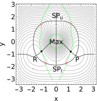
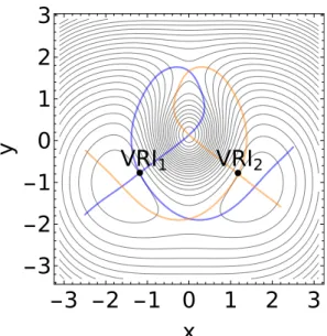
Figure 6: A modified Eckhardt surface98 with the stationary points, the minimums R and P, SPl, SPu, and Max. The intersections of the GE curves (gray thick lines) with the BBP condition,
Det(H) = 0, (green lines) give the optimal BBPs (red), or the VRI points (black). The optimal BBP1is located at the point (-0.89,-1.7), whereas the optimal BBP2is at the point (0.85,-1.7).
for the two minimums of the reactant, R, and of the product, P and still more for the two SP of index 1, the low SPl and the upper SPu. The PES has a heigh center, an SP of index two, labeled
by Max, see Figure 6. As we can see with the level lines, on this PES, the upper reaction pathway taking place through the SPuis energetically very higher with respect to the lower one that occurs
through the SPl.
There are two VRI points between the reactant, R, and the maximum, as well as between the product, P, and the maximum, see Figure 6. Two singular NTs connect all these points shown in Figure 7. Further VRI points are outside the shown figure, near the y-axis through x = 0.
Starting at the reactant, R, we find three families of NTs for a pulling to the two SP of index 1. One direct family is shown in Figure 8, and in Figure 9 we develop to one NT of the family the corresponding effective surfaces. Shown are three cases: panel (a) shows a low force, panel (b) a medium, and panel (c) shows a higher force. Figure 10 also explains a pathway to the lower SPl.
VRI
1VRI
2-3 -2 -1 0
1
2
3
-3
-2
-1
0
1
2
3
x
y
Figure 7: Singular NTs on the modified Eckhardt surface of Eq.(2) in SI. Each singular NT con-nects the respective VRI point with all stationary points of the surface. Blue: NT through VRI1,
orange: NT through VRI2. Two branches of the respective singular NT form here a common loop.
The first family in Figure 8 realizes a direct connection between reactant, R, and product, P. This kind of direct chemical corridor is of type 1. In our two-dimensional problem is the corridor characterized by the set of all regular NTs located between the two singular NTs (which are de-picted in blue and orange colors). The singular NTs are the borders of the corridor, compare the former Section. The chemical corridor contains the two optimal BBPs of the pulling, as well as of the reverse pulling, enforcing the optimal reactions from R to P, or from P to R. We recall that the optimal BBPs are at the intersection of a GE curve with the Det(H) = 0 or BBP manifold (green lines). These points are in the reactant or in the product valley.10 They are denoted by red points
in the Figures. The realm of the corridor is a directional angle of ≈ π/2 for the gradient direc-tion. It is here large because the reactant, R, and the product, P, are interconnected by a not strong curvilinear reaction coordinate. The respective optimal NT which meets the optimal BBP could be compared with a steepest descent curve from SPl, the Intrinsic Reaction Coordinate (IRC).62
However those parts of the NTs which come near to the VRI points are by no means a steepest descent curve. We need here with the class of NTs a new kind of curves to describe the pulling process.
P R NTlow VRI2 VRI1 BBP2 BBP1 SPl SPu -3 -2 -1 0 1 2 3 -3 -2 -1 0 1 2 x y
Figure 8: Direct pulling corridor of type 1 on the modified Eckhardt surface: all NTs going directly R↔P form this family. Two singular NTs are the borders of the corridor which touch the VRIs, as well as the lower BBPs; they are colored by blue and orange. All NTs between the border lines belong to this corridor. The red points are the optimal BBPs. They are on the green curves which depict the condition Det(H) = 0. Small dishes depict the convexity border of the PES. The reaction valley region is in between the convexity border. A second, compact branch of all NTs goes through the SPu and the maximum. The one loop of the gray, thick NT is shown alone. The
surface without load is shown in the background for comparison.
The set of regular NTs that belongs to this type 1 chemical corridor satisfy the MEP condition73
since these NTs are located in the valley containing the minimums R and P and the SP of index 1. Pulling along any regular NT of this corridor leads to a BBP that is near to the optimal BBP, that is BBP1 if we are pulling from R, BBP2 if we are pulling from P. If we start a pulling at the
R side, then the SPl and the minimum R coalesce under this pulling, and the reaction is enhanced.
We show in Figure 9 the action of a pulling along the thick gray, regular NT of Figure 8. It is named NTlow. It is observed that the pulling force results in a displacement of the reactant and SPl
along this NT. As the magnitude of the force, F, increases, these two stationary points get closer and, eventually, they coalesce above a given external force (see Figure 9). The force direction is l=(0.983,0.185)T and its Fmax = 4.25. The value of Fmax is the gradient norm at the intersection
point between the regular NT and the BBP manifold depicted as a green line. In Figure 9 we shown three cases for F, namely, F=1.4, 2.8 and 4.25 force in arbitrary units. For F=4.25, the
lower SPl and the reactant minimum, R, coalesce at the BBP line, see panel (c). Indeed, the
effective stationary points move on the same regular NT. The Det(H) = 0 condition also results for every F in the same curve. For the regular NT of the pulling direction we show additionally its other compact branch passing through the SPu and the maximum. On this branch the SPuand
the maximum move together. In this action the SPumoves downhill in the direction to the reactant
minimum R, but the displacement is very small. For this reason the behavior of SPuin this pulling
action does not play an important role.
(a) P R NTlow SPl SPu -3 -2 -1 0 1 2 3 -3 -2 -1 0 1 2 x y (b) P R NTlow SPl SPu -3 -2 -1 0 1 2 3 -3 -2 -1 0 1 2 x y (c) P Shoulder NTlow SPu -3 -2 -1 0 1 2 3 -3 -2 -1 0 1 2 x y
Figure 9: Effective PESs, Vf, of the modified Eckhardt surface98 with l=(0.983,0.185)T and (a)
F=1.4, (b) F=2.8, and (c) F=4.25 arbitrary unit force. Here the localizations of Re f f, SPl,e f f and
SPu,e f f are marked by points.
Note that the force employed to induce the coalescence between reactant and SPlin Figure 9 is
larger than the optimal force, that is to say, the minimum force that is needed to favor the process. Interestingly, in this particular case, the optimal NT coincides with the singular NT depicted in orange in Figure 8, which defines the border of this corridor. The optimal F value there is still smaller: Fmax = 2.956. The direction of the optimal NT through BBP1 is (0.878,-0.478)T. It is
clear that the pulling is reversible by an inverse pulling direction. Under the inverse pulling, the lower SPl and the product minimum move together and eventually coalesce.10,11The VRI points,
VRI1 and VRI2, are the border marks of the ’direct’ family of NTs of type 1. The VRIs are the
black bullets in Figure 6 to Figure 11 (excluding Figure 9). One should expect that such a de-scribed corridor is the usual case for pulling directions: in one direction, the reactant and an SP move together and form the well known transition state stabilization (TSS) of enzyme catalysis,46
P
R
NT
lowVRI
2BBP
1BBP
4-3 -2 -1 0
1
2
3
-3
-2
-1
0
1
2
3
x
y
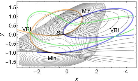
Figure 10: An asymmetric type 3 chemical corridor on the modified Eckhardt surface.98 All the NTs connect the minimums R and P in an indirect manner, i.e., they go through the SPl, Max, and
SPu. Two singular NTs are the borders of this corridor; they are colored by blue and orange. The
blue singular NT crosses the VRI2two times in the product valley, the orange singular NT touches
two VRIs outside of the Figure, near the x = 0-line. The black points are VRIs. The red points are the optimal BBPs. The surface without load is shown in the background for comparison.
enhancing the reaction rate. But one should expect that pulling into the other, inverse direction makes that the product and this same SP move together and again form a TSS, now for the en-hanced back-reaction. The reason for this expectation is simply the SP structure: in both directions of the SP valley the potential energy decreases along the steepest descent. However, we find be-low that the direct pulling corridor (of type 1) is usually very small, and that there other types exist.
Under the first corridor in Figure 8, the second family of NTs starts from minimum, R, to the lower SPl, see Figure 10 where again the border NTs are colored by blue and orange. However, its
NTs turn after the lower SP uphill to the maximum in between the two SPs, then go to the upper SP, and further they turn back to the product, P. The possibility of a connection by regular NTs of an SP of index one and an SP of index two is given by the index theorem for NTs.99 Observe that
the NTs of this corridor, especially the parts on the ridge between the SPl and the SPu, are by no
means any kind of minimum energy path. A further new property of the corridor is that it does not connect directly the reactant and the product. The effect of pulling on this family is very close to
P
R
NT
upVRI
1BBP
2BBP
3-3 -2 -1 0
1
2
3
-3
-2
-1
0
1
2
3
x
y
Figure 11: An asymmetric type 3 chemical corridor on the modified Eckhardt surface.98 All the NTs connect the minimums R and P in an indirect manner, i.e., they go through SPu, Max, and
SPl. Two singular NTs are the borders of this corridor; they are colored by blue and orange. The
blue NT touches the VRI1two times, the orange NT touches two VRIs outside of the figure, on the
x= 0-line. The red points are the optimal BBPs.
the previous studied case, namely, the reactant, R, and the SPl move together to form a TSS and
coalesce at least. Now also the SPuand the maximum move together.10,11 With this behavior, the
family of NTs defines a new type of chemical corridor, labeled as chemical corridor of type 3. Note that this corridor is indirect. In other words, this corridor does not go directly to the product. In this type, an inversion of the pulling direction starting from the second minimum, P, does not lead to the SPl, it leads to the SPu. Thus the pulling along the type 3 corridor shows an intrinsic
hysteresis. Of course, the hysteresis concerns here the mechanical corridor, its curve of FDSPs, but not possible chemical reactions over SPl. The reverse direction of pulling can turn the reaction
of the molecule over the upper saddle. There the original SP height and the Fmax at the respective
BBP4are much higher.
A representation of the effective PESs for different forces, F, for a pulling direction from a corridor of type 3 is given elsewhere.10,11 An important aspect emerging from the analysis
pre-sented above is that small changes in the direction of the external force in any chemical system statisfying an Eckhardt–like PES can result in drastically different scenarios due to the switch of
the type of corridors. Starting from the minimum, R, only small variations of the pulling direction, l, can decide between a pulling effect of the type 1 or type 3. The pulling itself works like in the first case: the SPl and the reactant, R, move together and coalesce, at least. However, at the same
time, the SPuand the maximum move together.10,11Thus we find usually no TSS for the SPu.11
VRI2 VRI1 VRI3 VRI5 VRI6 VRI4 BBP2 BBP1 BBP3 BBP4 R P I Max SPl SPu SPi -2 0 2 4 6 -2 0 2 4 6 8 VRI2 VRI1 VRI3 VRI5 VRI6 VRI4 R P I Max SPl SPu SPi -2 0 2 4 6 -2 0 2 4 6 8 VRI5 VRI6 TP TP R P I Max SPl SPu SPi -2 0 2 4 6 8 10 -2 0 2 4 6 8 VRI2 VRI1 VRI3 VRI5 VRI6 VRI4 R P I Max SPl SPu SPi -2 0 2 4 6 -2 0 2 4 6 8 VRI2 VRI1 VRI3 VRI5 VRI6 VRI4 R P I Max SPl SPu SPi -2 0 2 4 6 -2 0 2 4 6 VRI5 VRI6 TP R P I Max SPl SPu SPi -2 0 2 4 6 -2 0 2 4 6
Figure 12: Singular NTs on the Rhee-Pande surface. (See Supplementary Information Eq.(S3).) The upper panels shows the NTs through the points VRI1, VRI3, and VRI5, but the lower panels
shows the NTs through the points VRI2, VRI4, and VRI6. There are further VRI points outside of
the region displayed, see Supplementary Information for further details about these VRIs.
Contrary to the lower SPl, to attain the higher SPu from R by a pulling, we have to chose
directions from a next family of NTs, shown in Figure 11. It is the mirror picture to the corridor of Figure 10. The mirror line is the y-axis for x = 0. The optimal BBP3 of the family is at point
(-1.22,1.45). Its Fmax= 13.182 is more than four times larger than the Fmax at the lower BBP1. The
direction of the optimal NT is (0.502, 0.865)T. After crossing the SPu, the optimal NT turns uphill
and connects the two SPs, the SPuand the SPl and it still crosses the maximum, the SP of index
this family, the upper SP and the reactant move together and coalesce, at least. However, on the other side of the PES, the lower SP and the maximum move together, thus, the barrier height of the lower SP increases under the pulling directions. It causes a decrease of the thermodynamical rate over this former lower SP, compare Ref. 11. This kind of an indirect corridor is again a pulling of type 3.
The deviation of pulling directions from a type 1, direct chemical corridor is expected to greatly increase for a high-dimensional PES. In two dimensions, like in our examples of the present study, there is one col direction along the SP and one orthogonal direction uphill the SP ridge. On an N-dimensional PES the one direction along the valley remains, however, there is an (N-1)-dimensional ridge where orthogonal directions can break out off the col.
The three discussed corridors exhaust the full 360oof pulling directions of the plane in the left
minimum, R, in Figure 8, Figure 10 and Figure 11, as well as in the right minimum, P. Thus, here “forbidden”11or useless directions do not exist. The case is newly discussed in the next subsection.
The topography of the Eckhardt surface might be relevant, for instance, to rationalize the chem-istry associated with the cis↔trans isomerization of azobenzene derivatives, which constitute one of the most important classes of photoswitchable molecules. It has been observed that this isomer-ization can take place by means of two different reaction pathways: a rotation mechanism and an inversion mechanism.100Remarkably, pronounced hysteresis was detected in simulations in which
the isomerization was induced mechanically (either with a pull or push force).101
The ring opening in benzocyclobutene (BCB) is a next chemical example.31 BCB acts as a
twofold proof of our concept.
(i) An appropriate pulling force can enforce a symmetry forbidden reaction path, a conrotatory ring opening against the Woodward-Hoffmann rules. Thus, the respective pulling drives the molecule over a higher SP of the PES.
(ii) By the use of two experimentally different pulling directions one gets two different amounts of force or a literally opening of the molecule, F1=1400 pN against F2=900 pN. We assume that
both directions are in the same corridor. However, the height of their BBP energies can be very different.11 Direction l1is the pulling mainly along a single bond, l2is the pulling mainly along a
double bond. The forces are applied by a direct anchor or a so-called lever-arm polymer anchor of the molecule.31
4.2
Alternate Pathways with Intermediates: The Rhee-Pande PES
102The examples studied in the previous subsection concern alternate pathways without intermediates. In this subsection we study the case of alternate pathways with an intermediate and its possible ef-fect on the pulling. We consider the case of the Rhee-Pande PES.102As before the surface has two
alternate pathways86,93where we can assume that different cases of a directed force, f, again enable
two different pulling pathway families with respective FDSPs. One sort of corridors leads over the low energy SP, but the other SP is energetically disfavored in the forceless case.59 Of course, the
two-pathway-model is still in the framework of minimal models,55 however, it easily illustrates
the theory outlined in section 2. For the two-dimensional test surface of Rhee and Pande102 for
the case of competing RPs an intermediate minimum emerges on the lower path. The intermediate is behind the lower SP and it has no influence on possible reaction rates for R→P reactions on this PES,11 however, here we will observe new types of pulling corridors. Again, between the two
competing SPs emerges a maximum, an SP of index two. The mathematical expression and the main features of the Rhee-Pandee PES are detailed in the Supplementary Information.
The putative simplicity of this two-dimensional PES model should not conceal our view on the variety of pulling corridors. To study the possible pulling corridors, we first show the singular NTs which form the corresponding borders of the corridors, in Figure 12. In comparison to the former example, there emerge the additional VRI3 and VRI4 in the product valley. Because there
an intermediate minimum exists, we find further VRI points on the central ridge of the surface, the VRI5 and VRI6, around the intermediate. A further VRI7 is discussed below; and we found two
extra VRIs that lie far outside of the region of interest from the chemical point of view. Note that two branches of the singular NTs through VRI1, VRI2, VRI5 or VRI6 form loops. However, the
singular NTs through the VRI3or VRI4are globally correct pitchfork bifurcations.69 VRI2 VRI1 VRI5 BBP3 R P I Max SPl SPu SPi
1
2
3
4
1
2
3
4
5
x
y
Figure 13: The direct small corridor between the two deep minimums, R and P. The border parts of the two singular NTs are drawn in blue (the NT throughVRI1) and orange color (the NT
throughVRI2). A usual regular NT is drawn by a gray line in between. It has a second branch
through Max and SPu.
There is a direct corridor named pulling of type 1, shown in Figure 13, like in the former ex-amples. This particular corridor is circumscribed by two singular NTs that mark the limits of a very small region of the configuration space. It is quenched between the two singular NTs through VRI1and VRI2, compare the left two panels of Figure 12. An NT inside the corridor is also shown
in gray color; it has a second, closed branch through the maximum, and near the two VRIs, and through the SPu. Of course, this second branch concerns the movement of the SPu and of the
maximum under a pulling along the direction of the included NTs of the type 1 corridor. The SPu
also moves downhill in direction of the minimums, R or P, along the NT. The movement however is smaller than that of the minimums, R or P, and the SPl together. The small changes in SPuthus
do not have relevant consequences from a chemical point of view when a force is applied to the corridor going through SPl. The corridor itself concerns the pulling over the low SPl.
(a) VRI2 VRI1 VRI3 R P I Max SPl SPu SPi
-2
0
2
4
6
-2
0
2
4
6
8
x
y
(b) VRI2 VRI1 VRI4 R P I Max SPl SPu SPi-2
0
2
4
6
0
2
4
6
x
y
Figure 14: Corridors of type 3. (a) Corridor between VRI2 and VRI3, but also VRI1 is almost
thouched. Some normal NTs are drawn by gray lines, but the border parts of the two singular NTs are drawn in blue and orange color. Optimal BBPs are red points. (b) Corridor between VRI1and
VRI4, here VRI2 is almost thouched. The surface without load is shown in the background for
comparison.
Two further corridors are indirect connections by NTs of the reactant, R, and the product, P. They are formed similar to the former case of the modified Eckhardt surface. They are indirect corridors of pulling type 3. One case is the corridor between the VRI2 and VRI3, see Figure 14,
panel (a) and the other case is the corridor between the VRI1and VRI4in panel (b).
The type of corridors displayed in Figure 15 and Figure 16 show a complicated behavior but follow the features of the precedent corridors. These corridors include useless half-corridors like that found in the description of the corridor of type 2. However, they are more complicated due to the higher complexity of the underlying PES. Nevertheless, starting at reactant, R, and using such a corridor enforces the reaction over SPl in case of Figure 15, or over SPuin case of Figure 16.
In these corridors the former relation between reactant, R, and the product, P, is fully discon-nected. This kind of corridors is named pulling of type 4. They start in the reactant region, at R , but after crossing the region of the maximum, they do not turn down to the product, however, they escape uphill into the mountains of the surface. The first case is the corridor between VRI3
(a) VRI3 VRI5 VRI7 BBP1 TP R P I Max SPl SPu SPi
-2
0
2
4
6
-2
0
2
4
6
8
x
y
(b) VRI6 VRI4 TP R P I Max SPl SPu SPi-2
0
2
4
6
-2
0
2
4
6
8
x
y
Figure 15: Corridors of type 4. (a) The corridor between the VRI3and VRI5is very ’unsymmetric’.
The singular border parts are drawn in blue and orange color. The corridor does not reach the product, however, escapes uphill after SPu. Note that some NTs of this corridor have turning
points (TP). (b) The corridor between the VRI4 and VRI6 is also very ’unsymmetric’. It escapes
uphill after VRI6. All NTs of this corridor have TPs between the start in R, and the SPu. The
surface without load is shown in the background for comparison.
and VRI5, see Figure 15 (a). It goes further uphill after SPu. At the beginning of this corridor, a
further peculiarity emerges by a VRI7, compare Figure 15. This VRI point is not a border point of
a corridor. The two upper branches of the singular NT form a compact loop like the NTs through the VRI1, VRI2, VRI5 and VRI6. Here, the loop does not cross further stationary points of the
surface.103 The normal NTs of the corridor can circumvent the singular point, and also the loops
in the back of it.
The closed circular branches of NTs which form the loop ’behind’ VRI7 form a region of the
PES which is not connected to the minimum, R, by a continuous NT. Such compact branches of NTs are described elsewhere.103 The unreachability of special regions, seen from the minimums,
also concerns the regions ’behind’ the VRI3and the VRI4.
The other corridor in the right panel of Figure 15 is the small corridor between VRI4and VRI6.
It goes further uphill after VRI6.
valley, in both cases. (Disconnected with the exception of the one singular NT forming the border: at the corresponding singular VRI point, the two corridors touch.) The regular NTs of the product side do not cross the (green) BBP line. It means that an inverse pulling is quite useless: it moves the product minimum in its valley, forward or backward, but not to a coalescence with one of the SPs. A pulling in such a direction cannot enforce the disappearance of the product side, indepen-dent from the amount of the force, F.
The last corridor is a circular region shown in Figure 16. It starts at R, uphill to a TP, then downhill to one of the two SPs, SPuor SPl, further to the maximum in the central region, and over
the contrary SP, and a corresponding TP back to the reactant minimum. The disconnection between the reactant, R, and the product, P, is still stronger realized. This kind of a roundabout corridor is again a pulling of type 2. The orange singular NT has a turning point (TP) near (0, −2). There the minimum, R, and the upper SPuwould coalesce if the force points in direction of this NT, and the
amount, F, is high enough. For the contrary case of an inverse force, the corresponding TP of the blue singular NT is near point (10, 8). There the minimum, R, and the lower SPl would coalesce.
Also the intermediate and the SPithen coalesce on one of the circles left and above the VRI points.
For a pulling in this roundabout corridor we find a simple switch between two competing SPs. They are enforced by the same force, only in forward or backward direction. Of course, the BBPs of special NTs can be of quite different height.
If one looks to the product side, there is a truly disconnected half-corridor in the product valley. The NTs of the product side do not cross the (green) BBP line. It means that an inverse pulling is useless from point of view of the product side. It moves the product minimum in its valley, for or back, but not to a coalescence with one of the SPs. A pulling cannot enforce a disappearance of the product side, independent from the amount of the force, F. The type 2 pulling corridor is in every case of a corresponding force a ’one-way’ enforced reaction R→P. In the forward direction, say with F > 0, it may lead over SPl. In the backward direction, say with F < 0, it may lead over
VRI5 VRI6 TP TP R P I Max SPl SPu SPi
-2 0 2 4 6 8 10
-2
0
2
4
6
8
x
y
Figure 16: The circular corridor between the border points VRI5and VRI6. A regular NT is drawn
by a gray line in between the borders. The border parts of the two singular NTs are drawn in blue and orange color.
There are no further directions for a pulling or pushing of the molecule at its reactant state. The six given corridors exhaust the full 360odirections of the right minimum. Only the forward (F > 0)
or backward directions (F < 0) describe a useful pulling, or a useless one. Thus, “forbidden”, or useless directions do not exist for the reactant,11 but thoroughly for the product side, compare the
Figure 15 and Figure 16.
We emphasize that for directions of all types of corridors we can here enforce the reaction R→P. All pullings make that the reactant, R, and a respective SP move together, along the re-spective NT, and coalesce at least, if Fmax at the BBP is fulfilled. The different types of corridors
concern, for this PES model, a possible question for a back-reaction only.
A key chemical process whose mechanism can be explained through a Rhee–Pande–like sur-face is the Diels–Alder reaction under the influence of an external electric field.34,76 The electric
oriented along the reaction axis, the reaction takes place via a two-step mechanism with a zwitte-rionic intermediate if and only if the electric field is larger (in absolute value) than a given thresh-old.76 According to the present theory, this threshold is associated with the force of the optimal
BBP point. On the contrary, for smaller fields or fields pointing in the opposite direction, the re-action takes place via a concerted mechanism.76 Therefore, fields in opposite direction pull over
different SPs, which gives rise to hysteresis. Different directions, li, of the force are automatically
given by different enantiomeric forms of the used molecule.34 In a well adapted direction, the
force of the field causes a fivefold increase of the reaction rate. On the other hand, the electric field can be turned back. A reversed field makes an increase of the ∆E‡ for an effective TS. Thus, the
reversion of the field does not lead to a TSS in the other direction, for the back-reaction. It could be a hint to the chemical corridor of type 3 where the NTs turn up after the SP to a maximum of index two on the PES, compare the Figure 10,
N H 2-methylenehex-5-en-1-imine N H N H N H H H 2-methylenehex-5-en-1-iminium
Figure 17: Cope reaction of imine and the 2-methylenehex-5-en-1-iminium ion.
the Rhee-Pande model is the Cope rearrangement,104 see Figure 17. The Cope reaction stands as
an example of [3,3]-sigmatropic rearrangement. It involves a stereospecific and concerted migra-tion of an allyl group along a second allyl fragment within a 1,5-diene with concomitant σ - and π -bond reorganization.105 This reaction is mainly reversible and very often needs strong reaction conditions. For the reason it is important to develop catalytic variants of the Cope rearrangement. Such developments are the metal-catalysts by Pd(II)106and gold by bonding to the diene π-system
and the substituents attached to the 1,5-diene. In the latest case the catalytic rate process can be enhanced if the substituents are electron-withdrawing with the addition of Brønsted acids.107
Ex-amples of these substituents are carbonyls and the iminium ions recently reported by Gleason and Kaldre.108,109We proof by doing the present theory that electron-withdrawing groups transformed
in ions enhance its catalytic rate. For the purpose we compute at HF/6-31G level of theory the Cope rearrangement of 2-methylenehex-5-en-1-imine, see Figure 17, both, the concerted and the non-concerted pathways. The non-concerted path is the lowest energy path, passing through a biradical intermediate, see Figure 18 (a).
The two transitions states joining this intermediate with the reactant and product minimums have a biradical character. The transition state which corresponds to the concerted path does not show biradical character. From this description and regarding the energy profile we can conclude that the PES of the Cope rearrangement of the 2-methylenehex-5-en-1-imine is topographically analog to the Rhee-Pande surface analyzed above. The BBPs were obtained from the calculation of the IRC curves for the concerted and the non-concerted pathways. These BBPs are approximated; they are not necessarily the optimal ones. They might not belong to a gradient extremal curve. The structures of the six BBPs are given in Figure 19 with the corresponding components of their gradient vector. According to the present theory, the analysis of these gradient vectors gives us the optimal external force to be applied to enhance the rate of the process. According to that explained in references 108,109 the protonated form enhances the rate of reaction. We proof that this experimental observation is in accord to the present theory. First we add a proton to each BBP structure and compute the gradient. The protonated BBP structures are the corresponding BBPs
V reaction coordinate TS concerted Reactant Intermediate Product TS 1 TS 2 BBP 1 BBP 2 BBP 3 BBP 4 BBP 5 BBP 6 2.4 47.9 12.7 20.9 33.7 37.0 18.6 17.3 9.7 5.2 11.6 reaction coordinate V Reactant-H TS-H 1 Intermediate-H TS-H concerted TS-H 2 Product-H 0.9 18.9 28.6 16.4 4.8
a)
b)
Figure 18: Energy profiles of the Cope rearrangement of the (a) 2-methylenehex-5-en-1-imine, (b) 2-methylenehex-5-en-1-iminium ion. The energies are given in kcal mol−1.
of the 2-methylenehex-5-en-1-iminium ion, see Figure 17. If we compare the normalized gradient vector under exclusion of the proton component with the normalized gradient vector of the original BBP structure, we observe a very good concordance.
More specifically, the new gradient on the original BBP geometry provoked by the presence of the proton, g0 = l0|g0|, where the gradient vector g0 and the normalized vector l0 do not have the proton components, forms with the original BBP gradient vector, g = l |g| an angle near to 60◦.
BBP 6 BBP 5 BBP 4 BBP 3 BBP 2 BBP 1
Figure 19: Structures of the BBPs for the concerted and non-concerted pathways corresponding to the 2-methylenehex-5-en-1-imine Cope rearrangement. The labels are that given in Figure 18 (a). The arrows are the gradient components.
at the same level of theory. The energy profiles for the concerted and non-concerted pathways are reported in Figure 18 panel (b). The form of this profile is in accordance to the behavior described in Figure 14 panel (a) of the Rhee-Pande surface. From these results we conclude that the protonation is an efficient catalyst however it is not the optimal catalyst according to the present theory.
4.3
Alternate pathways with different products: a modified BQC PES
110In this subsection we deal with the case of alternative pathways, each of them leading to a different product. Additionally, the products can be connected through another pathway. Such PESs are related with mechanisms of reactions where the reactant converts to different products.
The particular PES employed in this subsection, which is a modified version of a surface pro-posed by us,110 is shown in Figure 20 (the mathematical expression A reaction path opens from
Min
P2SP
1SP
2SP
PVRI
RMin
P1Min
R-
20
-
10
0
10
-
20
-
10
0
10
20
x
y
Figure 20: A modified BQC surface with the stationary points and some VRIs (black bullets), see E.(4) in SI. The green lines correspond to the BBP condition Det(H) = 0. The dashed line is the convexity border of the PES.
R to P1 right below, and a second reaction path opens from R to P2 right top, and also a valley
exists between P1and P2. In sum we have a curvilinear triangle of reaction pathways. The SPs are
separated by VRI points. The center is again an SP of index two. There is a slight asymmetry for the two SPs: the SP1is slightly lower in energy than the SP2.
In contrast to the first modified Eckhardt case, here we find three direct corridors of type 1, along the three assumed reaction pathways. To get the corridors, we have to set first the borders, the singular NTs of this PES. They are shown in Figure 21. There are valley-ridge inflection points between the reactant and the maximum, as well as between the two product minimums and the maximum, see Figure 21. Panel (a) shows the singular NT through VRI1, panel (b) the singular
NT through VRIR, and panel (c) shows the singular NT through VRI2. Further VRI points are
discussed later.
The singular NTs are the borders of the possible pulling corridors on the BQC surface. The three direct corridors are obtained for NTs between the singular NTs. Two direct corridors are
MinP2 SP1 SP2 SPP VRI1 MinP1 (a) MinR -20 -10 0 10 -20 -10 0 10 20 x y MinP2 SP1 SP2 SPP VRIR MinP1 (b) MinR -20 -10 0 10 -20 -10 0 10 20 x y MinP2 SP1 SP2 SPP VRI2 MinP1 (c) MinR -20 -10 0 10 -20 -10 0 10 20 x y
Figure 21: Three singular NTs on the modified BQC surface, see E.(4) in SI. They are the NTs which cross VRI points. They connect a respective VRI point with all stationary points of the surface. (a) NT through VRI1, (b) NT through VRIR, (c) NT through VRI2.
shown in Figure 22. Panel (a) shows the valley over SP1, but panel (b) shows the valley over SP2
The corridor between the two product minimums is discussed later. Note that every of the NTs which define these corridors are divided into two branches. One branch describes the FDSPs in the reactant valley of interest. The other branch is a loop in the contrary product valley. It describes the behaviour of the contrary SP and the contrary product minimum under a respective pulling. The contrary SP moves to the maximum and its energy increases, what is discussed elsewhere.10
Again, here emerges another type of corridor, the type 3, for NT directions outside the valley corridors. The first one is the corridor between the VRI1right below, and a VRI4at the top corner
of the shown region, see Figure 23 (a). Contrary to the former PES example (Rhee-Pande PES), the corridor is only at the beginning a type 3 pathway (for example, from R to SP1, then over the
maximum to SP2, but then down to P2. Thus, it goes not directly from SP2 to the aim, the P1
minimum. However, the minimum P2 is at the same time enforced by a pulling in a respective
direction to P1because the pathway P2to P1is an additional continuation here, a valley corridor of
type 1. So to say a type mixture happens between the type 3 corridor for the pulling of the reactant, and a type 1 corridor for an additional pulling of a possible state at P2to the aim P1. The enforced
reaction would go from R over an effective SP1, but also a molecule at state P2would be enforced
to react to P1. Note the spread of NTs over a wide region after SP2 in the panel (a) of Figure 23,