LAUREA SPECIALISTICA IN INGEGNERIA INFORMATICA
An efficient software cache hierarchies
partitioning system for predictable performance
Master of Science thesis of: Alberto Scolari Matricola 783795
Advisor:
Prof. Marco D. Santambrogio Co-advisor:
Dott. Davide B. Bartolini
hic illum vidi iuvenem, Meliboee, quotannis bis senos cui nostra dies altaria fumant, hic mihi responsum primus dedit ille petenti: “pascite ut ante boves, pueri, submittite tauros”.
Virgil, Bucolics I
In addition to the friends and the relatives who supported me during these latest years, some people gave a major contribution to this work: these few words are only a part of my thankfulness to them. My first thanks are for Filippo Sironi and Davide Bartolini, with whom I had the privilege of working at the beginning of this thesis. In addition to fun-damental suggestions and guidance, they gave me confidence, support and a precious example of competence and devotion to the work. Another thank is for Marco Rabozzi, whose talent for modeling and ra-tionality helped me to organize ideas and measurements.
Last but not least, I am pleased to thank my advisor, Marco Santam-brogio, for his guidance, his continuous incitements and his example: to push the best out of us, he always demands the best out of himself.
The advent of Chip-MultiProcessor (CMP) architectures in computing platforms allows the co-location of applications, which
run simultaneously on the same chip. These architectures are
at the base of distributed computing platforms, and in particu-lar of today’s cloud environments. These environments manage a diverse and hardly predictable workload, which causes computa-tional resources to experience increasing phenomena of contention, as applications running on the different cores may interfere with each other in using several hardware resources. Therefore, isola-tion of applicaisola-tions becomes a key aspect to ensure performance and Quality of Service (QoS) in such environments. Among var-ious components, the Last Level Cache (LLC) is one of the re-sources where contention is experienced most, and is fundamental to ensure applications’ performance. Although contention is a well known phenomenon in the research, even the most recent commod-ity CMPs do not provide effective mechanisms to alleviate it, and no widely accepted solution yet exists.
Page coloring is a technique well known in the literature that allows partitioning the LLC of commodity processors. This tech-nique exploits the position of data in main memory to control how they are mapped into the LLC. The evolution of CMP archi-tectures has increased the number of cache levels and introduced important modifications, while how page coloring works on these cache hierarchies has not been studied in detail. This work aims to investigate the possible advantages, limitations and trade-offs that derive from the usage of page coloring on such architectures. In particular, recent CMPs by Intel, namely those of the Sandy Bridge family, adopt a hash-based LLC addressing scheme. This addressing scheme changes how data are mapped to the LLC and, consequently, the effectiveness of page coloring. Considering such changes, this work aims to adapt page coloring to the latest Intel’s architecture, which power cloud platforms.
In our vision, cloud workloads can benefit from page coloring, leveraging isolation of applications in LLC to fulfill QoS require-ments. To prove our vision, we realized Rainbow , an implementa-tion of page coloring in the Linux kernel that partiimplementa-tions modern LLCs for user-defined sets of applications. We evaluated Rainbow with a set of computational-intensive benchmarks to show its
This work is organized as follows:
• chapter 1 provides a high-level view of cloud platforms and of the main issues they face to fulfill users’ requirements, while, at the same time, optimizing the utilization of their computational resources
• chapter 2 provides the necessary background, explaining the architecture of modern LLCs; it also shows how control-ling physical memory allows controlcontrol-ling the LLC and, con-sequently, how the software layer manages physical memory • chapter 3 shows the techniques to obtain isolation in the LLC, offering a general view of the state of the art and of actual unsolved issues
• chapter 4 discusses the design of Rainbow in the context of the modern cache hierarchies, focusing on the the recent Intel’s architectures
• chapter 5 investigates Intel’s Sandy Bridge architecture by reconstructing the hash function of these CMPs
• chapter 6 explains how Rainbow is implemented within the Linux kernel, based on the design in chapter 4 and on the findings of chapter 5
• chapter 7 reports the results obtained running Rainbow with a set of benchmarks, showing how it can improve isolation and provide strict guarantees on applications’ performance • chapter 8 discusses the results, the limits and possible work
deriving from the proposed solution, in the context of cloud platforms.
L’avvento delle architetture Chip-MultiProcessor (CMP) nelle piattaforme di computazione permette la co-locazione di applica-zioni, che eseguono contemporaneamente sullo stesso chip. Queste architetture sono alla base delle piattaforme di calcolo distribui-to, in particolare dei recenti ambienti di cloud-computing. Questi ambienti gestiscono un insieme di applicazioni variegato e diffi-cilmente predicibile, che causa crescenti fenomeni di contesa sulle risorse condivise, dal momento che le applicazioni che eseguono su cores differenti possono interferire fra di loro nell’utilizzo di diver-se risordiver-se hardware. Perciò, l’isolamento delle applicazioni diventa un aspetto fondamentale per assicurare le prestazioni e la qualità del servizio, o Quality of Service (QoS), in tali ambienti. Fra vari componenti, la cache di ultimo livello, o Last Level Cache (LLC), è una delle risorse più contese, ed è fondamentale per assicurarne le prestazioni delle applicazioni. Nonostante tale fenomeno sia ben noto nella ricerca, anche i più recenti CMP comunemente reperibi-li sul mercato server non offrono meccanismi efficaci per alleviarla, e nessuna soluzione con largo consenso esiste ancora.
Page coloring è una tecnica ben nota nella letteratura che per-mette di partizionare ls LLC dei comuni processori server. Questa tecnica sfrutta il posizionamento dei dati nella memoria centra-le per controllare la loro posizione nella LLC. L’evoluzione delcentra-le architetture CMP ha accresciuto il numero di livelli di cache e in-trodotto importanti modifiche, mentre il funzionamento del page coloring su tali gerarchie di cache non è stato studiato dettagliata-mente. Questo lavoro si prefigge di investigare i possibili vantaggi, limitazioni e compromessi che derivano dall’utilizzo del page colo-ring su queste architetture. In particolare, i recenti CMPs di Intel, ossia quelli della famiglia Sandy Bridge, adottano un indirizzamen-to della LLC basaindirizzamen-to su hash. Quesindirizzamen-to schema di indirizzamenindirizzamen-to cambia come i dati vengono mappati nella LLC e, di conseguenza, l’efficacia del page coloring. Considerando tali cambiamenti, que-sto lavoro si prefigge di adattare il page coloring alle più recenti architetture Intel, che equipaggiano le piattaforme cloud.
Secondo la nostra visione, le applicazioni cloud possono trarre beneficio dal page coloring, sfruttando l’isolamento delle applica-zione nella LLC per soddisfare requisiti di QoS. Per dimostrare la nostra intuizione, abbiamo realizzato Rainbow , un’implementazio-ne del page coloring per il kerun’implementazio-nel Linux che partiziona le moderun’implementazio-ne
computazionalmente intensive per mostrare la sua efficacia, per discutere infine i risultati di questo lavoro, i limiti e possibilità di ricerca futura.
Questo lavoro è organizzato come segue:
• il capitolo 1 dà una visuale di alto livello delle piattafor-me cloud e dei maggiori problemi che queste devono af-frontare per soddisfare le richieste degli utenti, ottimizzando contemporaneamente l’utilizzo delle risorse computazionali • il capitolo 2 fornisce le conoscenze necessarie, spiegando
l’ar-chitettura delle moderne LLCs; inoltre, mostra come con-trollare la memoria fisica permette di concon-trollare la LLC e di conseguenza, come lo strato software gestisce la memoria fisica
• il capitolo 3 mostra le tecniche per ottenere isolamento nella LLC, offrendo una visione generale dello stato dell’arte e delle attuali problematiche irrisolte
• il capitolo 4 discute le scelte progettuali alla base di Rainbow nel contesto delle moderne gerarchie di cache, con particolare riferimento alle recenti architetture Intel
• il capitolo 5 approfondisce l’architettura Intel Sandy Bridge ricostruendo la funzione di hash di tali CMPs
• il capitolo 6 spiega come Rainbow viene implementato nel kernel Linux, basandosi sulle linee guida progettuali esposte in nel capitolo 4 e sui risultati del capitolo 5
• il capitolo 7 riporta i risultati ottenuti eseguendo Rainbow con un insieme di applicazioni di riferimento, mostrando co-me esso può migliorare l’isolaco-mento e fornire rigorose garan-zie sulle prestazioni delle applicazioni
• infine, il capitolo 8 discute i risultati, i limiti e possibili lavori futuri che derivano dalla soluzione proposta, nel contesto delle piattaforme cloud
List of Tables x
List of Figures x
1 Introduction and motivations 1
1.1 The context of cloud platforms . . . 1
1.2 Cloud platforms: applications and QoS . . . 3
1.2.1 QoS for cloud applications . . . 3
1.2.2 The provider’s view: resource provisioning . . . 4
1.3 Contention on the Last Level Cache of modern architectures 5 1.4 Proposed solution . . . 6
2 Background 11 2.1 Motivations and structure of modern caches . . . 11
2.1.1 Motivations of caching . . . 12
2.1.2 Structure of a cache . . . 13
2.1.3 Cache functioning models . . . 13
2.1.4 Cache addressing . . . 15
2.1.5 Other types of cache . . . 17
2.1.6 Cache hierarchy . . . 18
2.2 Contention on a Shared Cache . . . 19
2.3 Intel’s Nehalem and Sandy Bridge architectures . . . 21
2.3.1 Architecture of Nehalem . . . 21
2.3.2 Architecture of Sandy Bridge . . . 23
2.4 Buddy memory allocator . . . 26
2.4.1 Buddy data structure . . . 28
2.4.2 Buddy algorithm . . . 30 vi
3 State of the Art 35
3.1 Performance-aware scheduling techniques . . . 36
3.2 Hardware techniques . . . 38
3.3 Page coloring and software techniques . . . 41
3.3.1 Anti-pollution techniques . . . 43
3.3.2 Partitioning techniques . . . 44
4 Design 47 4.1 Vision . . . 47
4.2 Approach . . . 49
4.3 Cache hierarchy model and page coloring . . . 50
4.3.1 Assumptions on the cache hierarchy . . . 50
4.3.2 Partitioning Nehalem’s hierarchy . . . 51
4.3.3 Partitioning Sandy Bridge’s hierarchy . . . 53
4.4 Consequences of page coloring on applications . . . 55
4.4.1 Cache-Memory constraint . . . 55
4.4.2 Limits on physical page size . . . 57
4.5 Rainbow Buddy . . . 58
4.5.1 Mcolors and data structure modifications . . . 59
4.5.2 Algorithm modification . . . 61
4.6 Rainbow interface . . . 65
5 Reconstructing Sandy Bridge hash function 67 5.1 Assumptions and methodology . . . 68
5.2 Environment setup and preliminary considerations . . . . 69
5.3 Collecting colliding addresses . . . 72
5.4 Results interpretation . . . 74
5.5 Finding the correct hash function . . . 76
5.6 An educated guess: reconstructing the topology . . . 79
6 Implementation 81 6.1 Implementation approach . . . 81
6.2 Coloring the memory of a task . . . 82
6.3 Color management . . . 83 vii
6.4 Rainbow Buddy . . . 88
6.4.1 The modified Buddy structure . . . 88
6.4.2 The modified Buddy algorithm . . . 90
6.5 Implementation of the cacheset cgroup . . . 93
7 Experimental Results 95 7.1 Experimental environment . . . 95
7.1.1 Testbed and coloring parameters . . . 96
7.1.2 Test applications . . . 98
7.1.3 Experimental methodology and tools . . . 99
7.2 Application characterization . . . 99
7.2.1 Profiles in Nehalem . . . 100
7.2.2 Profiles in Sandy Bridge . . . 102
7.3 Isolation with mixed workloads . . . 103
7.3.1 Co-location in Nehalem . . . 105
7.3.2 Co-location in Sandy Bridge . . . 108
7.4 Isolation with more regular workloads . . . 109
7.5 Overall results . . . 111
8 Conclusions 113 8.1 Contributions . . . 113
8.2 Limits of the present work . . . 114
8.3 Future work . . . 115
8.4 Final considerations . . . 116
Bibliography 123
5.1 Minimum LLC latencies measured in Xeon E5-1410 when
accessing a slice from a core . . . 78
7.1 Selected SPEC CPU2006 tests . . . 98
7.2 Classification of applications . . . 105
7.3 Test workloads . . . 105
7.4 More regular test workloads . . . 109
List of Figures
2.1 Bit fields of a memory address to access a cache . . . 142.2 Lists of free areas of the Buddy allocator . . . 29
2.3 Coalescing of two buddies . . . 31
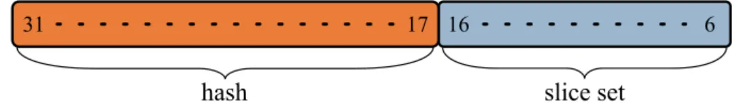
3.1 Bit fields of a physical memory address . . . 42
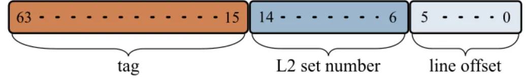
4.1 Physical address bit fields for Level 2 (L2) cache access . . . . 51
4.2 Overlap of color bits and L2 set bits in a Intel Xeon W3540 . 52 4.3 Utilization of address bits in Intel Core i7-2600 . . . 53
4.4 Color bits in Intel Core i7-2600 . . . 54 x
4.7 Rainbow Buddy data structure . . . 61
5.1 Reconstructed hash function of Intel Core i7-2600 . . . 68
5.2 Reconstructed hash function of Xeon E5-1410 . . . 78
5.3 Reconstructed topology of Xeon E5-1410 . . . 80
7.1 Applications profiles in Nehalem with different cache partitions101 7.2 Applications profiles in Sandy Bridge with different cache partitions . . . 104
7.3 Profiles of the workloads in table 7.3 on Nehalem, with dif-ferent cache partitions . . . 106
7.4 Profiles of the workloads in table 7.3 on Sandy Bridge, with different cache partitions . . . 109
7.5 Profiles of the workloads in table 7.4 on Nehalem . . . 110
7.6 Profiles of the workloads in table 7.4 on Sandy Bridge . . . . 111
S’io credesse che mia risposta fosse a persona che mai tornasse al mondo, questa fiamma staria senza piu scosse. Ma perciocché giammai di questo fondo non tornò vivo alcun, s’i’odo il vero, senza tema d’infamia ti rispondo.
Dante Alighieri, Divina Commedia, Inferno XXVI
This chapter explains the context of this research and presents the objective of our work. In particular, section 1.1 outlines the problem in the current scenario of Information Technology (IT), where the cloud computing paradigm is actually causing a shift towards different com-putational and economical models than those adopted so far. Then, section 1.2 focuses on cloud platforms and gives an overview of the goals that drive the management of computational resources and of the chal-lenges the providers face, highlighting the issues that are still unsolved with in the context of Chip-MultiProcessor (CMP) architectures. Fol-lowing on, section 1.3 focuses on the occurrence of contention in the Last Level Cache (LLC) even with the latest commodity CMPs and its impor-tant consequences for providers and users. Finally, section 1.4 outlines the solution we propose, its main guidelines and its evaluation.
1.1
The context of cloud platforms
The current scenario of computing services is becoming increasingly het-erogeneous and complex. The main trend visible in the current years is the shift of the computing paradigms towards a so-called cloud scenario [92, 65, 58], where external providers offer IT services to final users, who have access to computing resources only via a network. On the software
side, cloud platforms offer a wide variety of services, from direct access to a physical machine to high-level Application Programming Interfaces (APIs) [23, 10]. In cloud scenarios, the hardware and software deploy-ments are heterogeneous, as well as the various services these platforms offer to multiple categories of users, from single individuals to big com-panies [70]. Therefore, these platforms are inherently complex, and must fulfill multiple goals such as security, scalability, cost-effectiveness, etc. With the differentiation of cloud applications, the market of computing services introduced Service Level Agreements (SLAs) between providers and users [10, 66], which formalize requirements and guarantees about a certain cloud service into a contract between the parties. SLAs describe the technical parameters the service will provide in terms of Quality of Service (QoS) requirements: for example, a service can guarantee an upper bound on the Mean Time Between Failures (MTBF) or on the Turn-Around Time (TAT), an average throughput or other high-level metrics [31]. On the provider’s side, the management of cloud platforms pursues different goals, such as platform utilization and low energy con-sumption [4]. Thus, providers’ and users’ goals are often in conflict, and resource provisioning for cloud services is an open field of research [12]. The major computational resources in typical cloud environments are Central Processing Units (CPUs), in particular CMPs, which became the standard computational resources for servers and workstations over the past years. These architectures rely mainly on Thread Level Paral-lelism (TLP) to increase the performance, in accordance with Moore’s law [60], and are the actual and future trend [35]. These architectures allow co-location of different tasks on the same chip, achieving a higher computational density than previous single-threaded CPUs. Therefore, cloud environments largely employ CMPs in order to keep the utilization of the infrastructure high.
Yet, in actual commodity CMP architectures some resources can be explicitly managed from software (like cores), while others cannot, their control being exclusively up to the hardware. Thus, some of these re-sources are implicitly shared by running applications, with potentially detrimental effects. Contention on shared computational resources, such as the memory controller, the on-chip interconnection and the caches, limits the performance applications can exploit [49]. Contention phe-2
nomena exacerbate as the diversity of services increases, because how the variable workload of a cloud infrastructure uses the shared resources is hardly predictable [85]. Hence, isolation of shared resources has be-come a fundamental aspect for efficient computing infrastructures.
This thesis focuses on the LLC, a shared resource that is funda-mental for the performance of compute-intensive applications. Many research works have investigated contention on the LLC and proposed solutions requiring either hardware or software modifications, so that a wide literature is currently available. But these solutions remained con-fined in the research environment and have not been adopted by CMP designers nor by production-ready software environments. On one side, hardware solutions require big investments and actually do not provide a definitive, effective solution to contention. On the other side, software solutions are often ineffective or limited to specific scenarios, and can require deep modifications in the software infrastructure.
1.2
Cloud platforms: applications and QoS
This section presents the aspects of cloud platforms that are of inter-est for this work. Section 1.2.1 shows the main parameters to evaluate the services cloud environments provide and shows a simple classifica-tion of cloud applicaclassifica-tions with respect to their requirements. Then, section 1.2.2 introduces the main issues due to resource sharing.
1.2.1 QoS for cloud applications
SLAs define the service parameters to be guaranteed and are a part of the contract between the final user and the service provider that ensures the quality of the services provided and their cost [2, 89, 88]; these agreements specify QoS parameters that measure the quality of the service. These parameters often are of interest for both technical and non-technical users, and can also reach a high level of detail. SLAs also prescribe the interval these parameters must be within and the penalties in case of violation. Typical examples of QoS parameters are MTBF, throughput and response time. Some parameters are related to the availability of the service, while others are related to its performance. 3
In particular, performance requirements are experiencing an increasing demand [96, 81] and bring novel challenges to light. For example, latency is becoming a key requisite for user-facing applications, and providers often employ this metric to characterize the QoS of their service.
With respect to performance-related QoS, applications can be clas-sified in two broad categories: batch applications and latency-sensitive applications. Batch applications do not have a continuous interaction with users and do not have strict requirements in terms of latency; their typical QoS requirement is the completion time. A notorious example of batch application is MapReduce [24], but more and more applications with batch characteristics are being implemented for cloud platforms, also from the scientific world [27, 63, 89].
Instead, latency-sensitive applications have different QoS parameters to be satisfied. For example, Spark, a framework for machine learning [99], can be assigned latency constraints because it must respond to in-teractive queries. Typically, cloud platforms measure the time needed to service a request, from the instant it reaches the datacenter to the instant it exits. To measure and control the service QoS, previous work [3, 42] has shown that the 95-th (or 99-th) percentile of the latency dis-tribution is a good proxy for its QoS, while the mean can be misleading. Using the percentile ensures high confidence in evaluating the QoS of a service, imposing strict requirements to the provider. Instead, the mean does not take in account the statistical distribution of the latency, which can have long “tails”. Latency requirements are currently spreading also on common services like web search, e-mail and online gaming[56]. Pre-vious research showed that, in general, a platform can guarantee very low latency if the usage is low [91].
1.2.2 The provider’s view: resource provisioning
Unlike users, a cloud provider attempt to optimize different parame-ters, with goals that conflict with the user’s objectives. In particular, parameters like energy consumption and utilization are at the base of the management of cloud infrastructures and drive the design choices of providers [6, 44, 79]. Nonetheless, keeping utilization high while meeting sufficient performance levels is still a big challenge, and the research is 4
very live on this topic. For example, Barroso and Hölzle [4] show that the utilization of data centers computing resources seldom goes above 20%.
A first solution to maintain a sufficient level of performance is over-provisioning of resources, a solution that has, yet, a very high infrastruc-tural cost (server purchase, energy, etc.). On the contrary, decreasing the provisioning diminishes infrastructural cost, but implies the consolida-tion of more tasks onto a limited number of machines, sharing hardware resources. This sharing, in turn, leads to contention on those hardware resources that are not partitionable. Among all the shared resources (like disk bandwidth, network bandwidth, etc.), computational resources are the key of many applications. At the heart of them, CMPs architectures are a critical component where contention occurs, despite the continu-ous progresses in manufacturing technology and design. Indeed, while the computational power can be partitioned by core assignment and by time sharing (a long-living, well-known mechanism), other resources like the memory bandwidth and the LLC are not partitionable by design. Therefore, co-location of more tasks on a single CMP can cause con-siderable slowdowns [79], which can be intolerable for applications with strict requirements. This forces cloud providers to limit or even to avoid co-location at all [56].
1.3
Contention on the Last Level Cache of
modern architectures
The employment of CMPs in cloud platforms, although it allows the consolidation of more applications and thus a potentially higher utiliza-tion, forces the sharing of several resources, posing novel challenges the research is tackling. In particular, the LLC has a central role in ensur-ing applications’ performance, but is transparent in today’s commodity CMPs and is subject to unpredictable contention.
A wide literature already discusses the occurrence of contention on the LLC [28, 56], also within multi-tenants cloud environments [34, 61, 85, 33]. The occurrence of contention is particularly detrimental in these environments since it affects two aspects that are of fundamental impor-tance. The first aspect is the accounting policy: cloud platforms pro-5
vide pay-per-use services, where users typically pay for the amount of resources they rent over time (CMP cores, memory, bandwidth, etc.), expecting a certain, proportional performance. Nevertheless, “transpar-ent” resources such al the LLC have an important role with respect to final performance, and contention may cause the final performance to be different from the expected one, leading to unfair pricing policies. This contention, which depends on how the provider consolidates the work-loads, requires novel prediction models [33] and accounting policies. The second aspect pertains QoS requirements, and has already been introduced in section 1.1. In presence of contention, a provider cannot guarantee a priori a certain QoS without resorting upon over-provisioning [56], thus with additional costs.
Despite the vast literature upon contention on the LLC, researchers and manufacturers did not found a definitive way to solve it, nor an effective and widely acknowledged way to alleviate it. This reflects to CMP architectures, which still allow the occurrence of noticeable con-tention phenomena. Moreover, economical and legacy reasons prevent deep changes in CMPs, so that these issue are likely to remain unsolved for the upcoming years.
In particular, the latest commodity CMPs by Intel, namely the Nehalem and Sandy Bridge families, which power most of the cloud infrastruc-tures, do not offer any feature to tackle this issue. Therefore, the research has been actively working on a software technique called page coloring, which exploits the Phisically Indexed, Physically Tagged (PIPT) data mapping of modern LLCs [8] to partition the LLC and ensure isolation, as section 3.3 explains. Nonetheless, Intel’s Sandy Bridge family in-troduces a hash-based addressing scheme [52], which changes the PIPT mapping of data to the cache and makes “classical” page coloring infea-sible.
1.4
Proposed solution
Addressing this lack, this work proposes to make page coloring viable also on the Sandy Bridge architecture and onto a modern hardware/-software stack, so that modern cloud infrastructures can leverage the benefits of isolation.
Recent CMPs have deep memory hierarchies to hide the main mem-ory latency and offer new functionalities that conflict with page coloring. Therefore, this work deeply studies the consequences of these features with respect to page coloring and which restrictions derive from modern architectures, and provides the enabling technology to obtain LLC par-titioning also on recent architectures.
Since we aim to design a software LLC-partitioning capability, we will in-tegrate it within the physical memory management mechanism of recent Linux kernels. These kernels are the base of cloud platforms deploy-ments, and manage physical memory via the buddy algorithm. Taking in account the main goals of this algorithm and its implementation de-tails, we will show how our extension, called Rainbow , enhances it with page coloring capabilities in an efficient and non-disruptive way. This implementation will require the knowledge of the Sandy Bridge hash function, whose form will affect our design. Nonetheless, we will dis-cuss how to generalize our findings. Since also older architectures, with a “classical” PIPT-based LLC addressing, are still used, we will design Rainbow so that its basic mechanisms and its implementation can fit both Sandy Bridge and Nehalem architectures. This choice generalizes page coloring to a wide variety of recent and legacy architectures, the formers represented by Sandy Bridge and the latters by Nehalem. More-over, Nehalem’s addressing scheme is similar to that of many different architectures like SPARC or ARM, potentially extending Rainbow ’s vi-ability also on these platforms, which are nowadays appearing to the market of cloud platforms.
To provide an easy interface to isolate applications in LLC, we will also add a suitable interface, following the recent guidelines of Linux de-sign and the best use practices of large computing environments. Based on these guidelines, we will implement a cgroup interface [15] to expose Rainbow ’s capabilities to userspace, allowing the platform manager to handle the co-location of applications to different LLC partitions.
Finally, we will thoroughly evaluate Rainbow with reference bench-marking applications from the Standard Performance Evaluation Cor-poration (SPEC) suite [78], showing how Rainbow allows the platform manager to give an application a suitable LLC partition based on high-level policy and on QoS requirements. With Rainbow ’s technology, users 7
will be able to alleviate contention on the LLC for any set of applications of their choice, enhancing performance isolation and predictability.
To explain the relevant work in the field and our own work, this thesis is organized as follows.
• chapter 2 explains the necessary background knowledge to under-stand the architecture of modern CMPs, focusing on the LLC, and the functioning of the buddy algorithm, where Rainbow will integrate
• chapter 3 provides an overview of the state of the art, showing diverse solutions and highlighting unsolved issues with respect to LLC contention
• chapter 4 explains the design of Rainbow , showing how it specifi-cally take in account modern cache hierarchies, in particular those of recent Intel’s architectures Nehalem and Sandy Bridge, and how its capabilities are exposed
• chapter 5 shows a repeatable methodology to reconstruct the hash function of a Sandy Bridge CMP, providing insights on its physical layout
• chapter 6 explains the main implementation details of Rainbow , following the concepts of chapter 4 and the findings of chapter 5 • chapter 7 evaluates Rainbow ’s effectiveness and highlights its
achieve-ments and limitations in practice
• chapter 8 provides a more general view over the results of this work and over its limitation, highlighting possible future work and application scenarios.
In this chapter, we introduce the hardware and software components this thesis is based upon, in order to give the reader the needed background. Therefore, after a review of the motivations and of the structure of caches section 2.1, section 2.2 explains contention phenomena by discussing their sources and their consequences. Then, section 2.3 shows the details of the Nehalem [17][18, section 2.4] and Sandy Bridge [18, section 2.2] CPU architectures by Intel, which well represent the CMPs available in today’s server platforms and are thus the reference platforms for the purposes of this thesis.
Given the importance of physical memory allocation as in section 2.1, section 2.4 presents the goals and the functioning of the physical memory allocator of the Linux kernel, which will be at the heart of the proposed solution. Finally, section 2.5 explains a recent hardware capability that allows CMPs to easily manage large portions of physical memory, which is affecting the design of modern Operating Systems (OSs) and is to be considered in the context of this thesis.
2.1
Motivations and structure of modern caches
This section gives an overview of the structure of a modern CPU cache, starting from the basic reasons that led to the introduction of this com-ponent (section 2.1.1), explaining its structure, functioning and types (sections 2.1.2 to 2.1.5) and finally showing how multiple caches are organized into hierarchies within modern CMPs (section 2.1.6).
2.1.1 Motivations of caching
From the 80’s, the architectural and technological evolutions of CPUs and Random Access Memorys (RAMs) caused a diverging growth of the speed of these two components [36]. In particular, also the difference be-tween these two speeds grew up exponentially, in favor of the CPU. This ever-increasing difference created over the years the so-called processor-memory gap [13], forcing the CPU to wait for the completion of load and store memory operations and causing long idle intervals that limit the overall Instructions Per Second count (IPC) and decrease performance. Hence, the need of overcoming this bottleneck emerged, and designers chose to introduce an intermediate layer of fast memory that is invisible to both the CPU and the RAM memory, called cache1.
The design of this layer is based on the patterns of memory accesses found in real-world applications, which exhibit, each one to a certain degree, a characteristic called access locality. This behavior is the key principle caches are built upon, and is further distinguished in spatial locality and temporal locality. Without the need of a precise mathemat-ical definition (as given by Bunt and Murphy [9]), we can easily define spatial and temporal locality as follows.
Definition 2.1. (Spatial locality) if a (virtual) memory address a is referenced, it is likely that the addresses nearby will be referenced in the near future.
Definition 2.2. (Temporal locality) if a memory address is referenced at cycle c, it is likely that it will be referenced again at cycle in the near future.
Combining these two principles, we ca state that, if a block of words is referenced by the CPU, it is likely to be referenced again and multiple times in the near future. Caches are indeed designed to recognize these “local” patterns and keep data close to the CPU, and thus have a very different implementation than RAM memories.
In fact, caches are typically implemented with Static Random Access 1
as of the Oxford Dictionary, a cache is defined as “A hidden or inaccessible storage place for valuables, provisions, or ammunition”, from the French verb cacher, “to hide”
Memory (SRAM) technology. This technology has a greater cost in terms of area and energy with respect to the cost of main memory (typ-ically implemented with Dynamic Random Access Memory (DRAM) technology), but permits to build memories whose access time is much smaller. For these reasons, the size of cache memories is a careful trade-off that takes into account many parameters.
2.1.2 Structure of a cache
The basic granularity for data management inside the cache is the line (also called block ). A cache loads (or discards) the data in units of lines from main memory, where a cache line has a size that is bigger than a word and always a power of 2. For example, the line size in the x86 architecture is 64 B (with word of 32 or 64 bits), while in the Power architecture it is 128 B. A line stores contiguous words from main memory. Using cache lines bigger than the CPU word allows to leverage spatial locality, because the cache stores also the words that are adjacent to the requested one. To leverage temporal locality, a more complex mechanism has been designed and is explained in the following section.
2.1.3 Cache functioning models
Based on the trade-off between latency and performance, several cache designs exist, each one with a certain ability to leverage temporal local-ity. The most general model is the n-way set-associative cache, where n is usually an even number. This model divides the cache into2s sets,
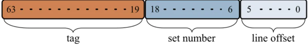
each set containing n lines. Using both line size and set number in pow-ers of two makes it possible to use subsets of the data address bits to look for a certain byte inside the cache. In particular, looking at fig. 2.1, the less significant l bits determine the offset of the referenced byte in-side the line, and are hence called line offset bits. Similarly, the higher s bits are the set number bits and determine the cache set. In this way, the lookup of the requested datum is easily performed starting from its address.
A third parameter, the associativity a, plays a fundamental role in the design and performance of a cache. Each set, in fact, is able to store a different lines having the same set number; to distinguish the lines inside 13
19
63 5 0
tag line offset
18 6
set number
Figure 2.1: Bit fields of a memory address to access a cache The physical address is divided into three fields for cache access: line
offset, set number and tag
a single set, the cache uses the remaining bits of the address, called tag bits, as a label associated to each line.
When a datum is requested to the cache, the cache controller reads the three fields of the address, accesses the set and searches the line having the requested tag. The tag value is searched in parallel over (ideally) all the a set lines, thus explaining why this cache is called “set-associative”. If the controller finds the line (this event being called cache hit ), it uses the line offset to fetch the requested data bytes. Otherwise, in case of cache miss, the controller fetches the line from main memory and must store it inside the set, in one of the a lines. To determine the line to place incoming data to, the cache controller looks for a free line by reading a specific bit that indicates whether the line is free; if it finds one, it stores the incoming line to the free location. Otherwise, the controller has to replace a line with the incoming one. To do so, the key idea is to choose the line that is less likely to be reused again in the near future, in order to keep in the cache the only data with highest temporal locality. Caches typically determine the reuse probability though the recent history of each line: in obedience to the principle of locality, the more recently a line has been accessed the higher its reuse probability is. Hence, to track the recent history, each line has an associated field called Least Recently Used (LRU) priority, which is set to 0 every time the line is accessed and incremented on every access to other lines. Based on this value, the cache controller chooses the least recently accessed line for replacement: it evicts this line, eventually writing it to main memory if it was modified while it was inside the cache, and stores the incoming line in place of the evicted one.
Moreover, modern caches also have additional units called prefetch-ers, which attempt to predict future memory accesses and load the cor-14
responding cache lines from main memory in advance, in order to mask the latency of cache misses. These units are widely present in today’s processors, which perform aggressive predictions of memory accesses [11] and may even anticipate accesses at various offsets [30].
In general, the parameters of the cache play a fundamental role in determining its performance and it cost in terms of power and area, introducing several conflicting goals. Therefore, the design of a cache is always a trade-off between different objectives. For example, to ex-ploit temporal locality at best the associativity should be maximal, to the point that all the lines a cache can holds lie in the same unique set (hence s= 0 and a is very big). In this cache model, called fully asso-ciative cache, the tag and LRU priority lookups involve a big number of lines, and need either a number of comparator circuits that is quadrat-ically bigger (to perform all the comparisons in parallel) or a very long lookup time, increasing the latency of every operation. Therefore, this model is not feasible in practice.
On the other side, a cache with a = 1 and maximal number of sets requires the least amount of area and power, and has minimal latency since no lookup is to be performed, but only the tag comparison between the requested address and the one of the line in the target set; yet, a= 1 implies that it is not possible to choose among several lines in case of re-placement, thus preventing the cache from leveraging temporal locality. Due to the low performance of this model, called direct-mapped cache, it was used only for small, low-latency caches in the past years, where the lithographic technology posed considerable lower bounds to the latency of the transistors.
Nowadays, despite the great progress of silicon lithography, the associa-tivity is still limited to a small set of values, usually ranging from 2 to 20. Conversely, the number of sets is quite high to hold big amounts of data even with limited latency: indeed, modern caches may have more than 2048 sets with a latency around 10 ns.
2.1.4 Cache addressing
As stated in the previous section, the cache uses the data address for the internal lookup. Yet, modern CPUs provide two address spaces for 15
data, the virtual address and the physical address. The physical address is the one used by the CPU to load data from RAM, is unique and is usually managed by the OS only. Instead, applications use virtual ad-dresses to reference memory and cannot handle physical adad-dresses. Each application has a separate virtual address space, which is mapped to the physical address by the OS in a way that is transparent to applications. Therefore, the same virtual address in the context of two applications can reference different physical locations in RAM. The translation from a referenced virtual address to the corresponding physical one is performed at runtime by the Translation Lookaside Buffer (TLB); this component resides in the CPU and its performance is fundamental.
Both address spaces can be used for cache addressing. Furthermore, as the cache needs to know both the set number and the tag, one address space can be used for the set and the other for the tag. Based on which address space a cache uses for which field, four model can be devised.
Instead, a Virtually Indexed, Virtually Tagged (VIVT) cache uses the virtual address for both the set number and the tag. Therefore, the TLB translation is noot needed to perform a complete lookup, minimiz-ing the latency. Yet, caches of this type suffer from two main problems, collectively called aliasing. Since each process has a dedicated virtual memory space, it may happen that the same virtual addresse refers two different physical location, depending on the running process: this is called the homonyms problem, and forces either the cache to add extra logic and internal state to disambiguate, or the OS to completly flush the cache in case of context switch, with an evident performance penalty. Conversely, different virtual addresses can refer to the same physical lo-cations (as with shared data or IPC mechanisms), thus creating multiple copies of the same data (synonyms problem). To solve this issue, a cache must track which lines contain to the same physical address, adding ex-tra logic that depends on the TLB lookup (even if not on the critical path of cache hits). Generally, since the solutions to homonnymity and synonymity problems have a high cost, VIVT caches are rare.
On the opposite side, in the PIPT model, the cache uses only the physical address for both the set number and the tag. With such scheme, all the addresses come from the same address space, ensuring their uniqueness inside the whole cache. Nonetheless, PIPT caches require 16
the TLB translation before accessing, and have thus a higher latency. However, thanks to the progress of the lithography and to the speed of TLBs most of the modern caches are implemented in this way.
Phisically Indexed, Virtually Tagged (PIVT) caches suffer from the same problems of VIVT caches and in addition require the TLB trans-lation to access the set, and are not used in practice.
Finally, Virtually Indexed, Physically Tagged (VIPT) caches can ac-cess the set in parallel with the TLB translation and do not suffer from the homonyms problem, but can still have synonyms. However, the caches have small latency, and are still used in small, fast caches.
2.1.5 Other types of cache
Other types of cache exist. A first type is the victim cache, which holds the lines evicted from the main cache; since this cache is accessed only after looking up the data in other caches, it can have a higher penalty and thus a higher associativity. This cache serves as an added layer between the normal cache and the main memory, can have a huge size (from 32 to 128 MB) and can be implemented with a technology having a smaller cost in terms of area and energy, like embedded Dynamic Random Access Memory (eDRAM).
Caches can be specialized to store only a certain type of data, for example those along the critical path of fundamental operations. Trace caches, for example, store small traces of instructions that are executed often. Similarly, a micro-operation cache stores instructions that have already been partially decoded: these caches are typical of the modern x86 architectures, which pre-decode the variable-length x86 instructions into fixed-length micro-instructions, which enter the CPU pipeline. To speedup the slow decoding phase of variable-length instructions, the pre-decoder stores groups of corresponding micro-instructions inside such cache in order to retrieve them in future, to reduce the bottleneck and the consumption of decoding. This technique, widely employed in the latest architectures by Intel, is particularly suited to speedup the execution of loops, whose body can be entirely kept inside the micro-operation cache and be decoded only at the beginning.
2.1.6 Cache hierarchy
As stated, the design of a cache for a given architecture requires numer-ous trade-offs. With the increment of the CPU frequency that occurred in the early 2000s and, later, with the advent of CMPs, the role of the cache has become increasingly important. Therefore the cache had to scale-up with the rest of the architecture, without causing bottleneck ef-fects. Since the latency of a single cache is determined by the number of sets and the associativity, even with the last technological enhancements it is impossible to build a unique cache with high size, high associativity and small latency. Thus, designers decided to organize different caches into a hierarchy of layers, where each layer has size and latency greater than the previous one. These layers increased in number during the years, and today’s server processors typically have three cache layers.
The lowest Level 1 (L1) caches are the first ones to be accessed for lookup and are very small, typically 32 or 64 KB, and are usually di-vided into a data cache and an instruction cache to realize a so-called Harvard architecture. The former cache contains only the applications data, which often exhibit higher locality than instructions, that the latter stores; to leverage this higher locality, data caches have higher associa-tivity. In order to limit latency (around 2 cycles), the L1 caches have small size and employ a VIPT addressing scheme. In CMP architec-tures, L1 caches are per-core, in order to provide to the core datapath a dedicated, fast memory and avoid contention with other cores.
In case of cache miss in the L1 layer, the subsequent Level 2 (L2) cache is accessed, which has greater size (typically from 256 KB to 8 MB) and has higher associativity (around 8), but also higher latency (typically 5 to 12 cycles). This layer of the hierarchy employs the PIPT scheme as the TLB translation is performed in parallel with the L1 access, so that no aliasing phenomenon is present. If this cache is the last layer in the hierarchy, it is shared among cores, otherwise it is per-core. In fact, in the latest years, the increasing amount of data CMPs must elaborate led to the use of such caches as per-core caches, while an upper Level 3 (L3) layer serves as shared cache and coordinates data sharing among cores. These L3 caches have even greater associativity (from 12 to 16), size (from 6 to 40 MB) and latency (from 20 to 40 cycles), presenting a 18
high hit ratio. This level is also called LLC, and is connected to the main memory via a controller, with a latency that is often in the order of 100 cycles. Typically, it is shared among all the cores, even if few CMPs have multiple independent caches shared between couples of cores. Because of the increasing number of cores and of the increasing LLC size, this last layer is often split into more slices (or tiles) that are interconnected with the cores. How the intercommunication system is designed depends highly on the model of the CPU, and the same vendor has developed, over the years, multiple solutions with different cost, performance and scalability. Therefore, the contention the cores may experience on the intercommunication varies highly, and we cannot assume a reference model for this system.
A key aspect of cache hierarchies is the coherency between multiple caches: when data are shared among cores, the cache lines containing those data are loaded into the lower layers of each core, and a coordina-tion mechanism must control whether these lines are modified and even-tually communicate the changes to the other cores (and CPUs in Non-Uniform Memory Access (NUMA) systems) to ensure data coherency. The state of the lines is tracked through the Modified, Exclusive, Shared, Invalid (MESI) protocol [64], which CPU manufacturers adapted over the years to their architectures producing variants like Modified, Exclu-sive, Shared, Invalid and Forward (MESIF) for Intel [87] and Modified, Owned, Exclusive, Shared and Invalid (MOESI) for ARM and AMD [54, 1].
Finally, CPUs can have specialized caches like a micro-instruction cache or an upper victim cache, but, here too, the solutions vary greatly based on the vendor and on the CPU family.
2.2
Contention on a Shared Cache
To understand the nature of this work and of those presented in the next chapter, we review how contention arises on shared caches. Given the structure of modern CMPs presented in the previous sections, we assume that only the LLC, either an L2 of L3 cache, is shared among cores, to focus on this level. This shared layer is where contention happens, hindering running applications scheduled on the cores.
Cache contention phenomena are divided in two main categories: thrashing and pollution. Thrashing [25] indicates that lines with high locality are evicted by other lines with high locality too, for the sim-ple reason that both sets of lines are mapped to the same cache set. This contentious pattern causes frequent transfers to and from the main memory, which become the performance bottleneck. Thrashing is typ-ical of co-scheduled, memory-intensive applications with good locality and is hardly predictable as it depends on the physical location of data in main memory, in turn depending on the OS, the workload, etc. Instead, pollution indicates that lines with low future reuse are evicting lines with higher future reuse. This phenomenon happens because of the LRU policy and of the limited associativity of a set: because of the limited space, the cache controller must evict a line to make room for the incoming one, assuming that this line will be reused in the near future. When this assumption is wrong, pollution happens and the evicted line, having greater locality, will be fetched again. This phenomenon is due to multiple sources, like non-local accesses to buffers [26] or the wrong access predictions of cache prefetchers [80].
The advent of CMP architectures exacerbates contention on the LLC by “mixing” the access patterns of various applications simultaneously running on the cores. In fact, the LRU policy at the basis of caches was conceived for single-core CPUs and is effective in capturing the ac-cess pattern of a single application, while it is unable to distinguish the different access patterns imposed by the cores, resulting in sub-optimal performance. It is to be noted that, despite data sharing among appli-cations happened also with single-core CPUs because of time sharing mechanisms, the time granularity of this phenomenon is order of mag-nitude greater than that of memory references, being the scheduling quantum around 10 ms; this caused the LRU policy to be usually very effective, with the exception of few, rare scenarios. Instead, in modern CMPs the access patterns mix with a much higher frequency, as cores can reference lines at intervals of few clock cycles, or even at the same time.
Although contention is widely studied in the research, commodity CMP architectures lack interfaces to control this phenomenon and prevent ac-cess patterns from mixing inside the LLC.
2.3
Intel’s Nehalem and Sandy Bridge
architectures
Today’s server CMPs have a complex structure, with an ever-increasing number of cores and a large LLC to hold the cores’ data. Intel’s architec-tures have a dominant position in the market of server CPUs [39]; in par-ticular, its most recent architectures, named Nehalem [nehalem_man, 17] and Sandy Bridge [sandy_man ], power the servers of recent com-puting infrastructures. Therefore, facing the contention over the LLC of these architectures is of primary importance to cloud computing infras-tructures.
Hence, this section explains the fundamental details of Nehalem’s and Sandy Bridge’s architectures, on which the proposed solution is con-ceived.
2.3.1 Architecture of Nehalem
Introduced at the end of 2008, the Nehalem architecture is the evolution of the previous Core architecture. It was designed to be modular, in order to be adapted to the various market segments (mobile, desktop, server) without re-designing large portions of the chip to comprise four or more cores. Inside the single core, the Nehalem platform provides new Single Instruction Multiple Data (SIMD) instructions, called Advanced Vector Extension (AVX) [19, chapter 5.13], and increased Simultaneous Multi-Threading (SMT) support, called Hyper Threading (HT) in Intel’s terminology.
Leveraging the progresses of silicon lithography, Nehalem is designed with a L3 cache as LLC, shared among all the cores, with a size from 4 to 24 MB. Lower caches are per-core, with a size of 64 KB for L1 data and instruction caches and 256 KB for the L2 unified cache. The L3 cache is inclusive, meaning that it includes all the lines stored inside the caches of all the cores: this property, typical of Intel’s LLCs, simplifies data coherency since per-cores caches can send coherency requests (via the MESI protocol of ita variants) directly to the LLC, without long snoop requests that would go through all the other cores.
Previous architectures, which had at most four cores, were conceived 21
M i s c I O M i s c I O Q P I 1 Q P I 0 Memory Controller
Core Core Q Core Core
u e u e Shared L3 Cache
(a) Die photo of a Nehalem CPU, from [37]. The GQ is in the middle of the chip to route memory requests and responses C3 C1 GQ (Global Queue ) IMC (Integrated Memory Controller) LLC Last level Cache QI (Intel® QuickPath Interconnect Controller ) Link Physical CSI 6.4 GH 1 .4-2 .3 G / C0 C2 QHL (QP Home Logic ) PC (Power Control Unit ) CRA
(Control Register Access Bus Controller )
GCL
(PLL Farm)
(b) Functional architecture of Intel’s Nehalem plat-form, from [22]. A GQ interfaces the components with the LLC, handling all the memory requests
(c) Units connected to the GQ, from [86] 22
with an L2 cache as LLC, and only later, high-end redesigns of the Pen-ryn architecture (Nehalem’s predecessor) comprised a shared L3 cache, exploiting the 45 nm lithography. In Nehalem, instead, the L3 cache is a basic element of the architecture, introduced to increase the mem-ory bandwidth needed by the higher number of physical and logical SIMD-capable cores. This L3 cache, despite the physical multi-bank design visible in fig. 2.2(a), is logically managed as a unique element. Figure 2.2(b) and fig. 2.2(c) also show how the on-chip interconnection sub-system, named GQ, connects the LLC to the cores, the integrated memory controller and the other components that handle Input/Out-put (I/O), inter-CPU cache coherency and power management. This interconnection sub-system is realized through a cross-bar structure to provide an efficient routing medium.
2.3.2 Architecture of Sandy Bridge
Pushing forward the evolution of the Nehalem architecture, Intel released the first Sandy Bridge models in early 2011, based on 32 nm lithography. The cores’ internal architecture has undergone several changes like the addition of further AVX instructions and a better energy management; an important change was the addition of an integrated, on-die graphic processor, making this architecture particularly suitable for laptops. Overall, the architectural model of the Sandy Bridge cache hierarchy also applies to the latest families, namely Ivy Bridge (that was a little more than a die-shrink of Sandy Bridge) and Haswell. Indeed, the new features introduced in Sandy Bridge proved to scale well with the lithography and the customers’ needs, and were maintained across the following families. Throughout this thesis, as we focus exclusively on the cache hierarchy, we will mention only the Sandy Bridge family for the sake of brevity, implicitly meaning also the subsequent CPU families.
In the cache hierarchy, the lower L1 and L2 layers are unchanged, while the L3 layer is notably different. Because of the new AVX instruc-tion with operands of 256 bits and of the higher number of cores, the Sandy Bridge architecture needs more bandwidth between the L3 cache and the other elements, such as the graphic, the memory controllers, the System Agent (Intel’s name for the CPU power controller), etc. Since 23
(a) Die photo of a Sandy Bridge CPU with integrated graphic, from http://images.bit-tech.net
(b) Ring interconnection of a Sandy Bridge-EP server CPU with integrated graphic, from www.qdpma.com
this architecture is designed to ship more cores than Nehalem, it also require better scalability of the cache bandwidth. To meet these goals, Intel split Nehalem’s unique cache into several parts called slices, one per-core with equal size and characteristics. To guarantee to each ele-ment access to a broad cache space, each eleele-ment can access all the slices through an interconnection sub-system. Figure 2.2(a) shows the on-die elements on a Sandy Bridge CPU with integrated graphic: all these elements communicate with each other, and in particular with the L3 slices, through a ring interconnection. Figure 2.2(b), instead, highlights the ring interconnection, a major novelty of the Sandy Bridge design [52]. The white boxes in fig. 2.2(b) are the interfaces that sense requests from the elements and assert replies on the rings. These interfaces are called cache boxes or ring stops. To let the bus bandwidth scale with the number of elements, the ring is fully pipelined: during a clock cycle, data flow from one cache box to the following one, according to the bus direction. Furthermore, two rings are present, with data flowing in op-posite directions based on the bus. Each slice has one cache box per ring, and a cache box serves both the slice and the core it is coupled with. Since, in total, two cache boxes are present per-slice, a slice can read requests from other elements and send replies simultaneously, with a routing protocol that chooses the best ring based on the bus occupation. To guarantee high bandwidth, ring buses consist of four rings for data, requests, acknowledge replies and snoops, respectively. In particular, the data ring is 32 B wide, so that a cache line (64 B) is transferred in two clock cycles. To avoid the performance bottlenecks of a centralized control, the arbitration protocol is distributed on each element and the coherency protocol running on the snoop ring is based on MESIF. The protocol governing the rings is, overall, undocumented, but Intel claims that, using separate buses for data, coherency and coordination, cache boxes can assert data and control messages on every clock cycle.
With such organization, multiple requests can be served simultane-ously, provided that they are directed to different slices. To ensure an even distribution of requests among slices and avoid bottlenecks, Intel computes the L3 slice a line must reside in by means of an undocumented hash function: physical addresses are hashed at the source and the data request asserted on the ring. This feature further ensures the scalabil-25
ity of the entire architecture and shows to the software a “fictitious” associativity that is higher than the real one. Yet, a first drawback of this addressing scheme is that the L3 access latency cores experience is variable, depending on the hop distance of the cache slice from the requesting core. Hence, this latency varies from around 21 cycles in case of hit in the local slice to almost 40 in case of hit in a distant slice. Finally, another drawback of this organization regards the power sav-ing capabilities. If the frequencies of the cache and of the cores differ, data requests suffer from a penalty that is proportional to the ratio be-tween the two frequencies. Therefore, Intel’s designers chose to place all the cores and the slices in the same voltage/frequency domain, avoid-ing intolerable latencies and performance bottlenecks due to different frequencies.
2.4
Buddy memory allocator
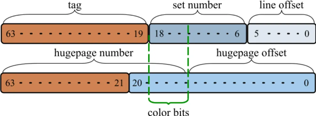
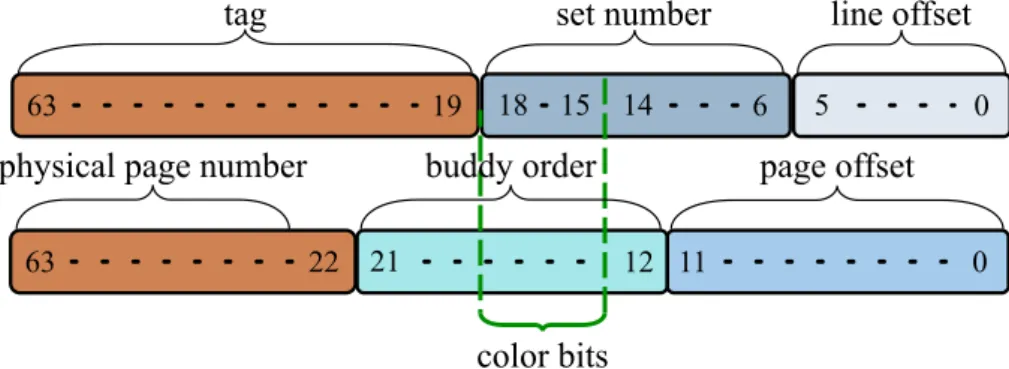
Since modern shared caches are PIPT, the cache set where data are placed depends on their physical address, either directly or through a hash function. Hence, for the purpose of this word, it is fundamental to understand how data in LLC can be controlled by mean of their physical address, which in turn depend on a component of the OS called physical memory allocator. This component manages the physical memory of the machine: when a subsystem of the kernel (such as the page fault han-dler, the Direct Memory Access (DMA) drivers, etc.) needs a portion of physical memory, it issues a request to the physical memory allocator, which allocates a contiguous physical area of at least the requested size. CPU architectures with virtual memory, such as those we consider through-out this work, pose several constraints to these memory areas; one of them is the minimum granularity of memory management, which is called page. Therefore, in these architectures the physical memory is allocated in multiples of the page. This size is always a power of 2: for example, it is 4KB on x86 architectures. The other main constraint is that memory pages have memory addresses that are always page-aligned. This alignment simplifies the virtual-to-physical mapping, that is per-formed by the TLB.
Because of the page alignment, a memory address can be split into 26
two bit fields: the less significant bits are the page offset and indicate the requested byte inside the page, while the most significant bits are the page address. This is the value the TLB has to translate from the virtual address space of a process to the physical address space of the machine. After the translation, the TLB outputs the physical page address and pads it with the offset bits to obtain the final physical memory address. Modern CPUs support also bigger page sizes, as section 2.5 discusses, but the basic granularity of memory management is usually small and architectures maintain rigorous legacy retro-compatibility.
Because of this small size, modern machines may have millions of pages: for example, an x86 system with 4GB of RAM memory has more than one million pages, and modern 64 bit servers may ship 64GB or more memory. The physical allocator is in charge of managing all these pages, and, in a modern operating system like Linux, must fulfill requests from many subsystems, with varying granularity and at a considerable request pace. Moreover, its performance should not degrade with the time and it should minimize memory fragmentation, which is a degra-dation phenomenon of memory areas. Memory fragmentation is due to internal and external fragmentation, and its limitation is a key design goal for allocators. Internal fragmentation is the waste of memory due to over-allocation, which happens because the allocator returns a memory area bigger than the requested one. Internal fragmentation depends on the page size: if the request is not an exact multiple of the page size, the allocator returns a higher multiple of pages and space wastage happens. Instead, external fragmentation indicates the interleaving between free and used areas: if external fragmentation is high, the allocator cannot allocate contiguous areas of big size because there are used pages “in the middle”.
Due to all the requirements we highlighted, a physical memory allo-cator is designed with several goals:
• efficiency: when a page is requested, it should be returned as fast as possible
• scalability: since machines have very different amounts of memory (from few MB to hundreds of GB), the allocator should handle memory areas efficiently
• keeping internal fragmentation low • keeping external fragmentation low
Efficiency and scalability highly depend on the implementation of the allocator, and thus vary. Instead, the main strategy to keep external fragmentation low is to reserve an amount of memory that is the clos-est possible to the one requclos-ested. However, the granularity of the page, imposed by the hardware, inherently causes some internal fragmenta-tion, which, for requests smaller than the page size, is handled by the upper layers (like application libraries). External fragmentation plays a more important role in modern computers, where a large amount of memory is often available. This fragmentation prevents the allocation of large memory areas to sub-systems that need it (like DMA drivers) and may cause severe performance degradation of the allocator, which could store many small memory fragments in its own data structures and perform long lookups. Therefore, complex heuristics exist to keep external fragmentation low and vary among OSs.
In Linux, the heart of the physical memory allocator is the Buddy algorithm [48]. It is known in the literature from almost 40 years and is widely used because of its capabilities. This algorithm is very effi-cient and is effective in limiting external fragmentation. Moreover, it has shown to scale well on a wide range of machines equipped with very different memory amounts [50].
The following sections show the functioning of this algorithm, with a focus on the implementation found in the Linux kernel. In particular, section 2.4.2 explains the data structure the algorithm is based on, sec-tion 2.4.2 explains how the algorithm leverages this data structure to perform the operations typical of memory allocations and section 2.4.3 explains an additional heuristic that is key in Linux’ implementation.
2.4.1 Buddy data structure
Within the buddy algorithm, physical memory is divided in parts called buddies. A buddy is a unique memory area with a size controlled through a parameter called order, where a buddy of order i is composed of 2i
physically contiguous pages. The order, is hence, the key parameter of a 28
...
0
9
10
1
buddy order
Figure 2.2: Lists of free areas of the Buddy allocator
buddy, and has an upper bound M that depends on the implementation: hence, an implementation manages areas of memory whose size ranges from 1 pages to 2M pages. Buddies are order-aligned, meaning that
the first page of the buddy has a page address aligned to a2i memory
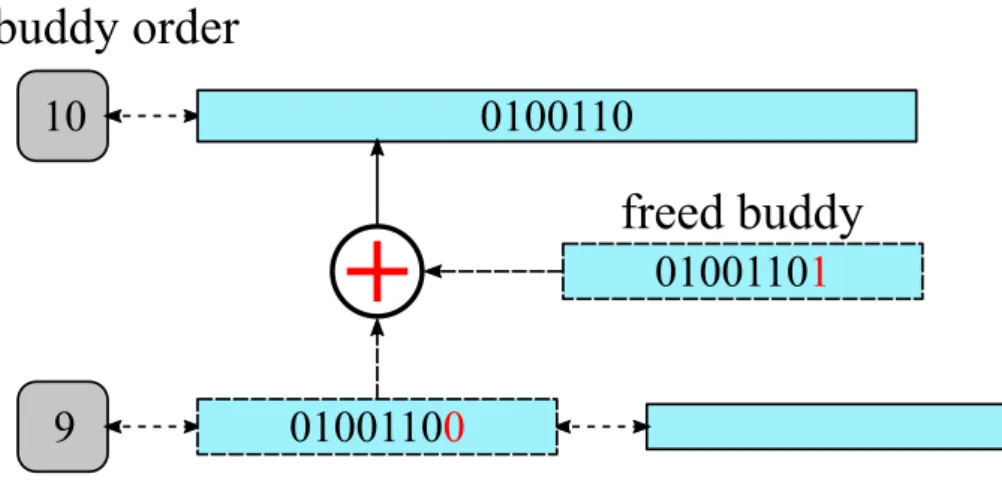
boundary. Hence, the page address of the first page of the buddy has the least significant bits set to 0, and is called buddy address. Thanks to these constraints, a buddy with a given order can be identified uniquely through its buddy address. The buddy algorithm is so called because it manages memory through buddies, trying to group them together to handle areas of size as big as possible. This grouping of areas reduces the number of elements the allocator handles, allowing scalability and efficiency.
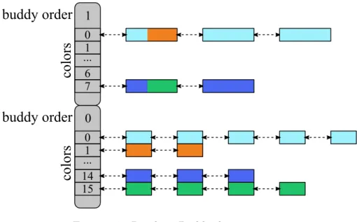
In Linux, the main data structure of the Buddy algorithm is an array of doubly-linked lists, depicted in fig. 2.2; each list links all the buddies of the a certain order, so that there are as many lists as buddy orders. Thanks to this structure, the allocator can satisfy memory requests of a certain order in constant time, as any buddy inside the list fits the request, the allocator simply extracts the head of the list. Conversely, when a buddy is released to be freed, it is added to the head of the list, thus still in constant time. For insertion and removal, the buddy allocator performs additional operations described in the next section.
2.4.2 Buddy algorithm
As from the previous section, the heart of the buddy algorithm is its efficient data structure. However, the mere insertion of buddies does not allow the grouping of them into bigger, less numerous memory areas, to maintain efficiency and scalability. On the opposite side, a list can be empty, so that a request of a given order cannot be satisfied. Solving these issues is the key goal of the buddy algorithm.
The buddy allocator responds to memory requests by allocating bud-dies of a certain order, which must be greater than or equal to the requested memory amount. In Linux the physical allocator accepts re-quests expressed only in buddy orders, and it is up to the higher kernel (typycally the slab allocator [57]) levels to round up requested sizes to the closest higher order. If this order is n, the allocator subsystem looks in the list of order n for free buddies. If no buddy is present, it splits a buddy at order n+ 1 in two buddies of order n; this operation is called buddy splitting and allows the allocator to vary the granularity of bud-dies in order to fit requested sizes. After splitting, the allocator stores one of the two halves in the buddies list of order n, and returns the other. Similarly, if also the list of order n+ 1 is empty, the allocator checks the list of order n+ 2 to contain buddies; if the list does, the allocator splits an(n + 2)-buddy in two n + 1 halves, stores one n + 1-half int the proper free list and further splits the other half as previously shown. Instead, if also the (n + 2)-list is empty, the allocator checks higher order lists and recursively splits buddies in the same fashion. Finally, if also the M -order list is empty, the allocation cannot be satisfied.
With these splitting scheme, the time complexity of the allocation is O(M ): since M is typically small (the default value in Linux is 10) every allocation has a strict time bound. Moreover, thanks to the logarithmic relation between the buddy order and the buddy size, even big requests can be fulfilled quickly. Starting the lookup from the smallest buddies is key to keep external fragmentation low. For the same purpose, Linux applies a small optimization: after a buddy split, the allocator always returns the lower half, so that its counterpart is stored in the free list and available for a subsequent allocation, without the need of splitting another buddy. Always using the same half has been shown to be more 30