Scuola di Ingegneria Industriale e dell’Informazione
Corso di Laurea Magistrale in Ingegneria dell’Automazione
A POINT-AND-COMMAND INTERFACE
FOR GRASPING UNKOWN OBJECTS WITH
ROBOTIC MANIPULATORS
Relatore: Prof. Andrea Maria Zanchettin
Correlatore(i): Prof. Paolo Rocco
Tesi di laurea di:
João Marcos Correia Marques, Matricola: 848958
ACKNOWLEDGEMENTS
First, and above all, I give thanks to God, without whose mercy I would no longer be.
I wish to thank Professor Andrea Zanchettin, for his patience, guidance and help were essential in the process of developing this project. Without his counsel and his expertise, the final demonstrations would not have been possible in the limited time available.
I extend my gratitude to Professor Paolo Rocco, who made this project a reality by allowing me to start the project way earlier than most – and for allowing my thesis presentation to be performed remotely.
Special thanks are also in order to Renzo Villa and Davide Nicolis, who’ve helped time and time again with the laboratory’s infrastructure and overall debugging of my code.
Special thanks go to Idil Su Erdenlig for helping me out with the final demonstration videos.
My gratitude also goes out to Gerardo Malavena for helping me out with the Italian Abstract! Gera, you’re the best!
Lastly, to my family, whose unwavering support provided me with the safest of havens in the hardest of times.
ABSTRACT
Automata are set to become ubiquitous in modern society, fulfilling assistive, collaborative industrial and domestic roles. In fulfilling these roles, the robots will come in contact with users of varied technical backgrounds, often having no special training for operating them. It is crucial, therefore, to provide novel ways in which humans may command them, lowering the barrier of entry to provide a safer, more intuitive and collaborative interactive environment. Pointing is one of the first ways humans interact with one another and throughout their lives it remains a very important element in human communication. As such, it is a natural candidate for being used as a means to interact with robots. Therefore, properly establishing an effective point-and-command human-machine interface comes as a natural milestone in the process of universalizing the application of automata. In interacting with robots, one of the crucial tasks to be performed is picking and placing objects. In domestic or uncontrolled industrial environments, the objects involved in these operations are often previously unknown. This work, thus, set out to provide a broad view on how human-robot interfaces have been done in the past, while proposing a different pipeline for commanding the grasping of unknown objects. This system proposes the use of an RGB-D sensor – the Microsoft Kinect – as a main visual sensor and by using its embedded skeleton tracking capabilities, is able to identify which object the user wants the robot to grasp (i.e. the object the user is pointing at) and autonomously generate a grasping pose for said object. The proposed system offers added robustness with respect to object traits, such as varying and non-uniform colors and different lighting conditions of the scene by applying an extension of Felzenszwalb and Huttenlocher’s graph-based image segmentation algorithm instead of traditional color tresholding or background removal techniques and by implementing a different kind of Point-Cloud filtering technique that allows it to reduce the effect of false-negative identifications in the image segmentation step.
ESTRATTO IN LINGUA ITALIANA
Gran parte delle previsioni indicano che i robot diventeranno onnipresenti nella società umana, integrati in tutte gli ambiti della nostra vita - domestici, professionali e personali. Questa onnipresenza, però, presenterà una grande sfida, mai affrontata per coloro che hanno il compito di progettare i robot, cioè il cambiamento radicale del profilo degli utilizzatori e del contesto nel quale il robot è adoperato.
Con la diffusione dei sistemi automatici, la classe degli utilizzatori, che inizialmente comprendevano soltanto operai specializzati da aziende, includerà elementi meno esperti, dal momento che non sarà possibile dedicare all'intera popolazione il tempo e le risorse che inizialmente venivano destinati agli operai.
Inoltre, in particolar modo per gli assistive robot, l'utilizzatore potrebbe non essere capace di interagire con il robot in modo convenzionale; questo potrebbe essere il caso delle persone disabili, impossibilitate nell'utilizzo, ad esempio, persino della tastiera con la quale avviare un dispositivo vigilante.
Di conseguenza, sia per questioni di sicurezza che di praticità, l'interfaccia uomo-macchina deve diventare necessariamente più semplice ed intuitiva. Inoltre anche nell'ambito industriale, in cui gli utilizzatori continueranno a possedere una formazione tecnica adeguata e le difficoltà associate alle persone con disabilità sono meno rilevanti, l'area dei robot sarà interessata da importanti cambiamenti.
Con l'avvento dell'Industria 4.0, vi è una crescente richiesta di un ambiente industriale che sia più dinamico e più flessibile, che permetta di modificare sia il prodotto finale, sia la disposizione delle macchine e degli operati all'interno dell'azienda. Per questi motivi, l'approccio tradizionale con il quale sono programmati i robot di oggi, caratterizzati da traiettorie fisse e hard-coded (cioè difficili da
modificare, dal momento che alcune volte è richiesta buona esperienza in diversi linguaggi di programmazione), presto non sarà più adeguata per grande parte delle nuove aziende.
Dato questo paronama, è evidente che vi sia la necessità di introdurre nuove tecniche per programmare gli automi futuri,e ci sono già numerose proposte che prevedono un'interfaccia uomo-computer che faciliterebbe questo incarico.
Alcune soluzioni (come, ad esempio, il caso di Matlab e Simulink) mirano a questo obiettivo introducendo elementi visuali nel linguaggio di programmazione, che prende il nome di programmazione con blocchi; queste alternative, sebbene siano utili ai fini dell'apprendimento della programmazione, sono a volte molto limitanti.
D'altro canto, vi sono anche altre alternative che propongono di utilizzare mezzi più intuitivi.
Sin dai primi anni della sua vita, l'essere umano è infatti abituato a interagire per mezzo di gesti, i quali rappresentano per l'uomo la tecnica più diffusa di comunicazione a breve distanza.
Per questo motivo un'interfaccia uomo-macchina che sia capace di capire e processare i comandi emessi per mezzo dei gesti sarebbe molto intuitiva e semplice da usare.
Infine, una tra le attività più basilari dei robot è quella di raccogliere e posizionare oggetti; dal momento che i nuovi robot saranno usati in ambienti e contesti sconosciuti, è conveniente sviluppare una Human Machine Interface (HMI) che sia robusta rispetto a variazione ambientali e delle caratteristiche degli oggetti.
Sulla scorta del discorso che è stato presentato finora, questa tesi si dedica a studiare e proporre un metodo alternativo alle tradizionali HMI basato sul paradigma
point-and-command per operazioni di prelievo e posizionamento di pezzi per
manipolatori robotici.
Dopo aver effettuato un'ampia ricerca sullo stato dell'arte, è stata identificata un'importante mancanza nelle HMI proposte, cioè che esse fossero allo stesso tempo robuste a variazioni ambientali (a causa delle tecniche di rimozione di fondo usate) e a variazioni nelle caratteristiche degli oggetti (a causa delle tecniche di identificazione degli oggetti manipolati).
In riposta a questa mancanza, è stata proposta una nuova interfaccia che usa il paradigma point-and-command; essa utilizza una tecnica di segmentazione di immagini basata sulla teoria dei grafi e lo skeletal tracking per identificare l’obiettivo del manipolatore. I risultati ottenuti in questo modo sono sia robusti rispetto all'ambientazione, sia rispetto a molte caratteristiche degli oggetti, come ad esempio colore, riflettività e struttura.
Per la sua semplicità e robustezza, la pinza utilizzata è di natura a ventosa, e la strategia di generazione delle configurazioni di grasping è basata sulle euristiche ricavate dalla letteratura; esse consistono nell'afferrare l'oggetto nelle aree più piatte della sua superficie e quanto più vicino possibile al suo centro di massa.
Il risultato finale è stato quello di ottenere una HMI funzionale, comandata unicamente tramite gesti, capace di funzionare in ambienti generici e di permettere la manipolazione di oggetti di diversa natura; essa può essere utilizzata anche affiancata ad altri moduli di controllo per fornire un'esperienza più intuitiva e sicura per gli utilizzatori non esperti.
Infine, un ulteriore e importante contributo di questa tesi è stato quello di
segmentatzione di immagini che ne migliora la versatilità, e una tecnica innovativa per filtrare le nuvole di punti migliorandone la robustezza.
FIGURE LIST
Figure 1 - Worldwide annual supply of industrial robots [1] ... 2
Figure 2- ABB teach-pendant [18] ... 4
Figure 3 -Simplified Robot Control Workflow ... 7
Figure 4 - Taxonomy for robot autonomy classification[24] ... 11
Figure 5 - [53]'s pipeline for vision-based distance calculation ... 18
Figure 6 - Ancona's Image Segmentation Algorithm in Pseudo-code [76]... 27
Figure 7 - Domestic objects that would provoke failure in threshold-based segmentation techniques [92] ... 28
Figure 8 - Outlier removal through density filtering [93] ... 30
Figure 9 - Performance comparison of WLOP on a scan of a Japanese lady statue[94]... 32
Figure 10 - Example of surface normal smoothing [76] ... 34
Figure 11 - Gripper planar approximation [76] ... 35
Figure 12 - Performance of DeepLab in Cityscapes dataset [98] ... 39
Figure 13 - Lasagna, my dog, under several edge detection schemes ... 41
Figure 14 Image segmentation algorithms evaluation [96] ... 46
Figure 15 – High-Level Proposed System Workflow ... 49
Figure 16 - Kinect Skeletal Model [120] ... 50
Figure 17 - Interpreter Workflow ... 51
Figure 18 – Original Target Identification Algorithm ... 52
Figure 19- Simplified Infrastructural Diagram ... 54
Figure 20 - Experimental Setup with FRIDA and the Kinect ... 54
Figure 21- Use case diagram of the instructive system ... 56
Figure 23 - Kinect V2 Reference Frame [125] ... 58
Figure 24 - Original Color Image ... 59
Figure 25 - Color Images Converted to Depth Space ... 60
Figure 26 -Depth Image a) before and b) after filtering ... 60
Figure 27 - Pseudo-code for the FH algorithm ... 63
Figure 28 - Pixel neighborhood definition ... 65
Figure 29 - Test Segmentation of the scene in Figure 24 ... 66
Figure 30 – Target Identification Algorithm ... 67
Figure 31- Raw red helmet extracted point cloud ... 68
Figure 32 - Extended point cloud ... 69
Figure 33 - Point-cloud filtering algorithm using two point-clouds... 70
Figure 34 - Point cloud progression ... 71
Figure 35 - Suction Gripper Grasp Generation Algorithm ... 73
Figure 36 - Several views of the grasping pose... 75
Figure 37 - Top view of Frida's workspace ... 81
Figure 38 - First test: Matte black mouse on white matte surface ... 82
Figure 39- Four nearly identical mice in black table surface ... 83
Figure 40 - Four final objects ... 84
Figure 41 - Summary of the results of the first experiment ... 85
Figure 42 - Second Experiment: Leftmost mouse ... 86
Figure 43 - Second Experiment: Middle left mouse ... 86
Figure 44 - Second Experiment: Middle right mouse ... 87
Figure 45 -Second Experiment: Rightmost mouse ... 87
Figure 46 - Depth image from Figure 45 ... 88
Figure 48- Third Experiment: White Mouse ... 90
Figure 49- Third Experiment: White Box ... 91
Figure 50- Third Experiment: Banana ... 91
Figure 51- Banana Picking Video Screenshots ... 92
Figure 52 - Banana picking Video Screenshots (II) ... 92
EQUATION LIST
Equation 1 -Point Cloud Density in a neighborhood K of point i ... 29
Equation 2 - Density Filter Definition ... 30
Equation 3 - Definition of uniformity filter [76] ... 30
Equation 4 - Definition of the iteration of WLOP ... 32
Equation 5- definition of vj ... 32
Equation 6- definition of 𝑤𝑖𝑘 ... 32
Equation 7 - Rapidly decreasing weighting function ... 32
Equation 8 - Surface normal ni ... 33
Equation 9 - Smoothed surface normal ñi ... 33
Equation 10 - Stabilit score with centroid ... 36
Equation 11 - Heuristic estimate of the center of mass of a point cloud ... 37
Equation 12 - Stability score using PECOM ... 37
Equation 13 - Robot Motion Score SRM(G) ... 38
Equation 14 - Global performance index S(G,P) ... 38
Equation 15 - Definition of PR ... 43
Equation 16 - Expected value of NPR ... 44
Equation 17 - Estimation of p'ij ... 44
Equation 18 - Definition of VI ... 44
Equation 19 - Local Refinement Error ... 44
Equation 20 - Global Consistency Error ... 44
Equation 21- Generic Edge Weight Definition ... 61
Equation 22 - Definition of internal difference ... 62
Equation 24 - Definition of the minimum internal difference MInt ... 62
Equation 25 - Definition of the homogeneous transformation ... 71
Equation 26 - Definition of 𝑻𝒊𝟐 ... 72
Equation 27 -Euler angles, given γ is zero ... 75
Equation 28- Rotation matrix of the End Effector ... 76
Equation 29- Quaternions from rotation matrix ... 76
Equation 30 - Dynamic Model of a Generic Manipulator ... 79
Equation 31- Definitions of B(q) and 𝐶𝑞, 𝑞 ... 79
Equation 32 - Residual (external) estimation ... 79
ACRONYM LIST
Acronym Meaning
PbD Programming by Demonstration
HRI Human-Robot Interface
HMI Human-Machine Interface
DCNN Deep Convolutional Neural Networks
FH Algorithm Felzenszwalb and Huttenlocher’s (FH) algorithm
PR Probabilistic Rand metric
NPR Normalized Probabilistic Rand metric
VI Variation of Information metric
GCE Global Consistency Error metric
INDEX
1. Introduction & Thesis Outline ... 1
1.1. Introduction ... 1
1.2. Objectives and Chapter Structure ... 6
1.2.1. Objectives ... 6
1.2.2. Chapter Structure ... 7
2. Bibliographic Review ... 9
2.1. Human Robot Interaction ... 9
2.1.1. Autonomy ... 9
2.1.2. Information Exchange ... 11
2.1.3. Team Structure ... 12
2.1.4. Learning and Training ... 12
2.1.5. Task-Shaping ... 12
2.2. Multimodal Human-Robot Interaction ... 13
2.2.1. Vision-Based Human Robot Interaction ... 14
2.2.2. Voice Based Human Robot Interaction ... 21
2.3. Autonomous Grasping ... 22
2.3.1. Model Based Grasp Synthesis ... 22
2.3.2. Recognition Based Grasp Synthesis ... 23
2.3.3. Machine Learning-based Grasp Synthesis ... 24
2.3.4. On-Line Based Grasp Synthesis ... 25
2.4.1. Threshold-based segmentation ... 39
2.4.2. Edge-based segmentation ... 40
2.4.3. Region-based segmentation ... 41
2.4.4. Watershed-based segmentation ... 42
2.4.5. Graph-based segmentation ... 42
2.5. Grasp generation for suction-cup grippers ... 48
3. Proposed Method & Implementation ... 49
3.1. Proposed Method ... 49
3.1.1. Interpreter ... 50
3.1.2. Grasp Generation Module ... 52
3.2. Implementation ... 53 3.2.1. Hardware setup ... 53 3.2.2. Software Implementation ... 55 4. Experimental Results ... 81 4.1. Description of Experiments ... 81 4.2. Result Analysis ... 84 4.3. Main issues ... 93
5. Conclusion, Improvements and Future Work ... 95
5.1. Improvements and Future Work ... 95
5.2. Conclusion ... 97
1. Introduction & Thesis Outline
1.1. Introduction
In its September 2016 press release, the International Federation of Robotics (IFR) highlighted that the annual supply of industrial robots in the world was expected to grow up to 60% by 2019, as seen in Figure 1. This large growth reflects the growing adoption of robotics and overall automation of industrial processes. This growth, however, is not directly linked with the traditional model of automation. As noted in [1], the current and future industrial environment differs from the past ones in many factors, including the need for increasingly more versatile manufacturing plants, increased interaction with non-specialized workers in the same work environment [2] and, consequently, increased complexity of tasks to be performed by the machines under a constantly shifting workspace. One example of this shift is the increase in research [3]–[5] and market availability of collaborative robots, such as ABB’s IRB 14000 YuMi, Rethink Robotics’ Baxter, Fanuc’s CR-35iA, KUKA’s LBR iiwa and Universal Robot’s UR3 UR5 and UR10. These robots are designed to be used safely in the same environment as humans without requiring usual safety features such as cages and no-go areas, allowing for deeper interaction between workers and machines.
Figure 1 - Worldwide annual supply of industrial robots [1]
Parallel to the Industry 4.0 movement, another important paradigm shift has occurred, in which the focus of robotics has been shifting from strictly specific industrial settings to more consumer, home and service-oriented environments, as noted by [6] and [7]. Under this new framework, an automaton is forced to interact with a highly disorganized environment, while being operated by a wide variety of users, which are likely not to have access to specialized training on how to operate such robots or, in the case of assistive robotics, may not have physical conditions to operate them the usual way – that is – through robot-specific programming languages.
When considering these scenarios for the future of robotics and automation, a flexibilization of the way robots are programmed is due in order to both lower the barrier of entry to their usage and speed up reprogramming industrial robots in a dynamic environment, as the rigid way conventional programming methods work ( by requiring the user to learn syntax and semantics of a proprietary robot programming language and exhaustively debugging the program) makes changing the robot’s task slow and difficult, even for trained operators, as highlighted in [8] and [9]. Moreover,
being able to freely and easily interact with the machine has been reported in literature as one of the crucial factors in determining the successful incorporation of robots into ordinary people’s lives [10], [11].
Many paradigms for human-robot interaction (HRI) have been proposed over the years trying to facilitate and make it more intuitive. In their survey of Robot Programming Systems [9], the authors separate those efforts in two fronts: Those of manual and automated programming. For them, manual programming systems are those that require the user to directly specify the robot’s actions in its code, while automatic programming allows users to specify the robot’s actions without ever directly changing the machine’s code. Relevant efforts in simplifying manual programming systems listed are generic procedural languages – such as Motion Description Language, for Java-; behavior based languages – like Functional Reactive Programming; Graphic Programming Interfaces - like that of Lego Mindstorms or the one presented in [12] as efforts in improving manual programming.
On the automatic front, learning systems like that of [13] are able to perform complex actions by joining together simply-defined ones using a conditioning protocol, whereas [14] uses kinesthetic teach-in to teach simple movements to the robot and use reinforcement learning to later allow the robot to perform more complex tasks by joining them together. [15] instructed a six legged robot on how to walk by performing Q-learning into each of the legs to learn optimal policies of movement given the goal to either swing or stand. Finally, [16] and [17] present an extensive survey on the use of reinforcement learning in robotics and which I shall not detail as they are out of the scope of this work.
Another approach to automated programming is programming by demonstration (PbD). In this paradigm, the user guides the robot through a
teach-pendant, like the one in Figure 2 - which allows for the direct control of the robot’s joint positions or of the robot’s end-effector’s 6 degrees of freedom- to guide the robot to its desired positions, recording those point’s coordinates at each step, which are later replicated by the robot. Some robots, collaborative robots in particular, allow the robot’s joints or end-effector to be manually moved to the set-points This facilitates the programming steps, but still requires training on how to operate the teach-pendant and basic knowledge of the robot-specific language, as some semantics of the programming language still need to be applied in order to specify the kind of motion to be performed between the registered spatial points – e.g. linear or circular motion and specifying the speed of motion.
Figure 2- ABB teach-pendant [18]
In addition to those methods, some additional paradigms have been presented, extending the concept of PbD by allowing for the use of multi-modal systems in the process of teaching. Teach-by-showing, for instance, allows automata to infer motion patterns from observing human subjects performing the goal task. For instance, in [8], a robot received the force, torque and position inputs of a human
demonstrating the goal activity of inserting a PC cart into a motherboard and used those to generalize subtasks and tasks and then perform those tasks by itself; [19] used a similar paradigm to teach a robot how to perform the ball-in-a-cup task and [20] used imitation learning associated with reinforcement learning to train a humanoid robot to grasp items in front of it, proving the potential of this strategy.
Finally, another programming paradigm is that of instructive systems. In this case, the robot already possesses a set of well-defined tasks and operations on which he has already been instructed – by means such as manual coding or any of the previously mentioned programming paradigms – and executes those tasks on demand based on human input, usually through gestures and voice recognition [9]. Examples of the application are found in [21] , which provided a system to allow for commanding a fetching robot using gestures and [22] provided a framework to identify complex gestural commands to be interpreted by the robot.
On a highly interactive work environment, this paradigm, which represents a very high-level kind of programming, is expected to be the most useful, as many of the industrial tasks to be performed are standard, but their targets, their order or their frequency are not well defined or fixed. Thus, allowing the users of the automata to freely assign it a specific task on demand by voice commands or gestures should provide the flexible workspace cooperation that is demanded from a modern industrial setting or the ease of use necessary for the application of assistive robotics in a domestic environment.
Considering the above-mentioned arguments, this work will focus on the study and development of a simple instructive system to command an industrial robot through a known set of gestures, captured by a Kinect V2.0, focusing on the task of identifying and grasping unknown objects within the fixed robot’s field of view, which
will start with an bibliographical overview of each of the isolated components of the project.
1.2. Objectives and Chapter Structure
1.2.1. Objectives
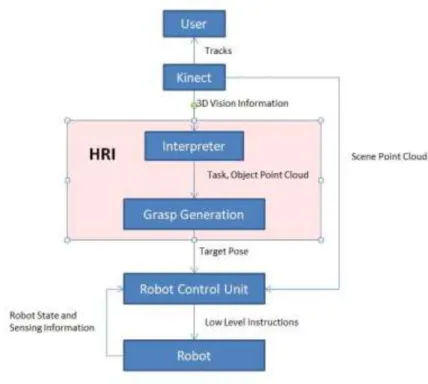
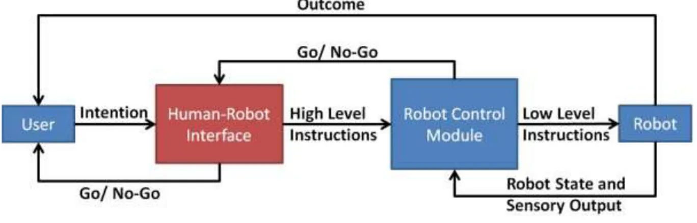
This work’s ultimate goal is to create a framework that can be applied in the creation of an instructive system that will allow users to command robots to perform grasping tasks using their bodies. In order to demonstrate this framework in action, a simple demonstration is designed, in which a simple instructive system that allows users to command a robotic manipulator that is fixed in space to pick completely unknown objects in unknown positions by using gestures captured by a Kinect V2.0 system, also fixed in space. Considering a modular approach to robot control, one may imagine it as shown in Figure 3. In this model, the user conveys his intention to the robot by whatever means (in the context of this work, it would be through gestures). The Human Robot Interface (HRI) then interprets this intention and turns it into a set of high level instructions to be followed by the robot, such as “place your end-effector at position pose P1 coming from pose P2”. This set of high level instructions is fed into the Robot Control Module, which will compute the set of low-level instructions to be given to the robot, such as the intermediate steps between the robot’s current position and the starting point P1 and the joint positions that the robot should assume in order to reach those poses, while also checking for the feasibility of those instructions and notifying the HRI when the instruction is unfeasible ( out of reach or in a singular position or would cause the robot to collide with itself or the environment).
Figure 3 -Simplified Robot Control Workflow
While much research exists in the area of robot control, focusing on avoiding singularities, solving kinematic redundancies and avoiding collisions, often achieving satisfactory great run-time performance, the field of development of HRIs still needs much work. Thus, this work will focus in the red module in Figure 3, while most of the already available modules for robotic control, such as collision detection, singularity avoidance and redundancy resolution being either bypassed completely or done in the simplest way possible- via hardcoding of solutions- in order to focus on the main goal in the limited time available for the development of the project.
1.2.2. Chapter Structure
In the framework for the creation of the HRI, three key aspects must be taken into account, namely:
Finding the most intuitive ways to interact with the robot;
Establishing the robot’s task given the command;
Generating the high-level description of the task to be fed into the robot controller.
In this work, each of these aspects will be dealt with in a more theoretical approach Section 2, Bibliographical Review. Section 3 will detail the proposed
system regardless of implementation, while the implementation details for the demonstration will be detailed in Section 3.2. Experimental Results will be displayed in Section 4 and Section 5 will present the closing remarks on the project and suggestions on how to improve upon this work.
2. Bibliographic Review
An instructive system is an integrated software solution, which involves many software components sewn together with the aim of allowing the final user to intuitively interact with the automaton. This interaction is done through multimodal systems of interaction, which provide a natural, human-like way through which commands are issued. The current state of the art for multi-modal HRI is described in detail in this section. In addition, instructive systems also rely on the existence of high-level functional blocks, which represent autonomous routines that implement each of the robot’s high-level commands. Some of these blocks, with special attention to autonomous grasping, are also presented in depth in this section.
2.1. Human Robot Interaction
In his survey on HRI, [23] defines the field as the search for ways to “understand and shape the interactions betweenone or more humans and one or
more robots”. In that context, the authors highlight five key attributes that define and
affect the interactions between user and robot. These are: Autonomy; Nature of Information exchange; Structure of the Team; Adaptation, learning and training of people and the robot and Shape of the task. Each of those attributes is briefly discussed in the following section.
2.1.1. Autonomy
Autonomy is a still much debated concept in robotics, as literature has not yet settled on a single definition that is appropiate for all contexts. Indeed, [24] presents a summary of such definitions, reproduced in Table 1
Table 1- Definitions of Agent and Robot Autonomy [24]
Definitions of Agent and Robot Autonomy
“The robot should be able to carry out its actions and to refine or modify the task and its own behavior according to the current goal and execution context of its task.” [25]
“Autonomy refers to systems capable of operating in the real-world environment without any form of external control for extended periods of time” [26]
“An autonomous agent is a system situated within and a part of an environment that sense that environment and acts on it, over time, in pursuit of its own agenda and so as to effect what it senses in the future;” “Exercises control over its own actions.” [27]
“An Unmanned System’s own ability of sensing, perceiving, analyzing, communicating, planning, decision-making, and acting, to achieve goals as assigned by its human operator(s) through designed HRI ... The condition or quality of being self-governing.” [28]
“‘Function autonomously’ indicates that the robot can operate, self-contained, under all reasonable conditions without requiring recourse to a human operator. Autonomy means that a robot can adapt to change in its environment (the lights get turned off) or itself (a part breaks) and continue to reach a goal.” [29]
“A rational agent should be autonomous—it should learn what it can to compensate for partial or incorrect prior knowledge.” [30]
“Autonomy refers to a robot’s ability to accommodate variations in its environment. Different robots exhibit different degrees of autonomy; the degree of autonomy is often measured by relating the degree at which the environment can be varied to the mean time between failures, and other factors indicative of robot performance.” [31]
“Autonomy: agents operate without the direct intervention of humans or others, and have some kind of control over their actions and internal states.” [32]
Although a single definition for autonomy has yet to be achieved, [24] propose several guidelines for categorizing it, most notably the one presented in Figure 4, where the author classifies and defines 10 Levels Of Robotic Autonomy (LORA) accoding to the roles taken by the user and the robot in the normal operation of the automaton, providing as well a brief description on how each LORA could be characterized and a list of few examples of those LORAs that were available in literature at the time.
Figure 4 - Taxonomy for robot autonomy classification[24]
These definitions account for several layers of autonomy and automatization of the process, allowing for a fine classification of robotic systems.
2.1.2. Information Exchange
As defined by [23], the way in which robots and users exchange information is also crucial in the proper analysis of a HRI. The media through which this information
is conveyed between them varies from visual displays presented as a Graphical User Interface (GUI) or Augmented Reality (AR) interfaces; gestures; speech and natural language; non-speech audio; and physical interaction and haptics. Though formerly employed mostly in a separate way, these interactive media have been facing an increasing pressure to be used in conjunction to one another, with crescent interest for multimodal interfaces [22], [33]–[35] , as they are deemed more intuitive and efficient in conveying commands than traditional separate methods.
2.1.3. Team Structure
Another crucial feature in an HRI analysis is defining who will be taking part of the interactions. Indeed, teams of humans and robots have different compositions when applied to different fields and each of these compositions requires different interaction protocols. For instance, a team composed solely of robots may use the fastest communication means available, whereas teams which contain one human and several robots have to abide by a slower communication protocol to allow human oversight – and teams with more than one human are subject to even slower communication constraints, to allow for human understanding and consensus.
2.1.4. Learning and Training
As remarked by [23], one of the objectives of a good HRI design is to minimize the training time for both users and robots without compromising the system’s operability. This may be done through increasing the robot’s learning capabilities or by making the interfacing intuitive to humans.
2.1.5. Task-Shaping
Another crucial factor in the design of HRIs is the attention to how the introduction of the robot to the task will affect how the human who is interacting with
him will change the way in which the task is done. Indeed, when designing an HRI the designer should ponder whether he may improve the process he is working on, rather than just replacing to some degree the human effort that was previously needed. Robots often do not have the same restrictions that humans do (such as temperature, orientation, positioning) and- as such- create new possible ways to perform a task, often much more efficiently.
That being said, we may conclude that the design of an HRI consists in finding a way for humans and robots to collaborate, while minding their environment, their interaction media, the shaping of the task at hand and the composition of the teams that are working on it. This process of collaboration relies heavily on the media through which we interact with those robots and thus, if we are to improve it, we need to provide the users with intuitive interactive interfaces. As noted by [36], humans naturally interact with the world using multiple resources simultaneously. It should be, therefore, simpler for them to interact with machines in a similar manner. Hence, the next session will detail the many scientific initiatives in providing multimodal HRIs.
2.2. Multimodal Human-Robot Interaction
Vision, hearing, touch, olfaction and gustation have long been considered the five basic senses, the gateways used by the human brain to communicate with the environment around it. Even though this paradigm has been facing scientific scrutiny over the past few years, as proprioception and balance are now often included in the list of senses, these 5 remain the main media of conscious human interaction with its surroundings.
Taste is mostly neglected as valid means of human-machine interaction due to its intrinsic contact-based chemical nature. Olfaction has seen some innovation with growing development of electronic-noses, applied in several fields , such as chemical
plants monitoring [37] and even object recognition [38], with varying degrees of success. Its use in the field of robotics is, however, still fairly restricted and thus left out of this survey.
With recent advances in haptics, touch is seeing an increase in usage as a form to enrich Human-Computer-Interaction (HCI), both in tele-operated robots, such as [39] and in virtual reality environments [40]. Though this dimension of multimodality shows promise in enriching user experiences in simulation systems, improving accuracy in tele-operated tasks, improving safety in human-robot collaborative spaces (with the implementation of tactile kill switches in industrial robots, often implemented in collaborative robots) and improving teaching by demonstration robot programming [41], it is not further detailed in this thesis for the sake of brevity, with the reader being referred to [42] for a broad survey of advances in the field, their methods and technologies, though a short detailing of force-feedback robotic programming is presented in the following section, as it was necessary for the implementation of suction-based grasping on a collaborative robot.
Considering the factors exposed above, most of the research pertaining to the field of multimodal HRI concerns the use of visual or auditory information to mediate the exchange of information between users and systems, being used in concurrency to improve the effectiveness of the process according to Wicken’s multiple resources theory [43]. An overview of the forms of unimodal audiovisual HRI paradigms will thus be provided first, alongside a brief overview of how they are being combined in the current research landscape.
2.2.1. Vision-Based Human Robot Interaction
By adding a visual input to a robotic system, many ways for interacting with them arise. In particular, visual systems that possess embedded depth sensing, such
as the Microsoft Kinect® allow for better tracking of human intention. All forms of visual-based HRIs can be seen as special cases of object detection and tracking. In their survey on object tracking, [44] provide an ample analysis of the field which is, alongside [45] the basis for this section. Visual-Based HRIs can be based in four main techniques, all subfields of object tracking: Blob Detection, Background Removal, Skeletal Tracking and Gaze Tracking, explained in further detail below.
2.2.1.1. Blob Detection
As defined by [45], a blob is :
“…a region inside which the pixels are considered to be similar to each other, meanwhile be different from the surrounding neighborhoods."
As such, they remark that blob detection methods rely mostly in identifying interest points and interest regions, with interest points being classified as extrema in scale-location spaces denoting regular regions, whereas interest regions being classified as irregular segmented regions that are considered “constant” in a given metric.
Classic interest point detection algorithms, such as Laplacian of Gaussian (LoG), Difference of Gaussian (DoG) and Hessian-Laplacian, rely on the construction of Gaussian pyramids in order to detect points of interest. LoG has a high computation cost due to the computation of second derivatives involved in its application and has in DoG an approximation of lower computational cost.. In both cases, the extrema of both pyramids are recorded as being LoG ad DoG points of interest, respectively. Another alternative method to locate points of interest is based on the Determinant of Hessian, in which the scale-normalized determinant of the Hessian matrix,𝜎4det (𝐻), is used to detect interest points.
The interest points indicated through these metrics can then be applied in many algorithms to detect key points in an image, such as Scale Invariant Feature Transform (SIFT, used in object recognition, visual tracking and baseline matching[45], [46]). Some methods, such as Speeded-Up Robust Feature ( SURF, which uses box filters approximations to generate efficient Hessian interest point detection [45], [47]), try to generate these points in a more computationally efficient way, while more modern methods, such as KAZE features [48] avoid Gaussian smoothing-induced blurring of the images by making use of nonlinear diffusion filtering techniques, preserving natural image boundaries though at a higher computational cost [45].
Another important component of blob detection is interest region detection. An interest region can be defined as a “region segmented from neighboring areas by exploiting the constancy of image properties” [45], like pixel intensities. One of the algorithms used to obtain interest regions is Maximally Stable Extremal Region (MSER) [49]. MSER is based on thresholding pixel intensities with several different thresholds and finding regions that remain stable over the largest number of different thresholds. Though not free from questioning [50], MSER is still used in many fields due to its simplicity. Other commonly used algorithms include Edge-Based Region (EBR) and Intensity Extrema-based Region (IBR) [51].
Regardless of the algorithms used, blob detection is usually used as an initial step in more complex image processing algorithms or for applications that do not require finely detailed knowledge of the objects surrounding the actor in the environment, such as obstacle avoidance [52].
2.2.1.2. Background Removal
Commonly used in the pre-processing steps of many complex computer vision algorithms, background removal can take many forms. If both the robot and the camera are fixed in space – and most of the robot’s workspace remains unaltered during its operation, one may resort to the technique applied in [53], in which the authors took an image of the workspace before the introduction of the robot and the human, which they labelled as reference image, which they edge-filtered using Laplacian Filters. Then, when it came time to detect the relevant objects in the scene, the authors took another picture, now with all the relevant elements within the camera’s field of view. After also edge-filtering the new image, they proceeded to take the difference between the two images and, through thresholding, determine whether an interesting object is located in a given position within the frame, i.e., the authors used the difference between images to determine what changed between frames and, knowing the reference frame was of an empty room, conclude that whatever changed must be an object. The authors later perform many post-processing steps to identify which objects were modelled- like the robot- and which were invading its workspace, like the human, and later used the labelled images to calculate the distance between them, enabling the implementation of a safety stopping monitoring mechanism. Though the implementation details are beyond the scope of this work, their processing pipeline is exposed in Figure 5.
Figure 5 - [53]'s pipeline for vision-based distance calculation
Though a rather complete survey of background removal techniques may be found in [54], [55], two other techniques are of interest within the scope of this project. One of them is presented in [56], presented here for the novelty of using traditional clustering technique K-means as a pre-processing background removal technique. The other one is presented in [57], which made use of Microsoft Kinect®’s depth camera to segment the image into foreground and background by means of auto thresholding, which is based on finding the valley following the first large peak in an image’s depth histogram.
Both these techniques allow for fast and slightly more detailed object identification, even though several more pre-processing steps are needed to render this new information useful in most settings.
2.2.1.3. Skeletal Tracking
In many interactive settings, the most intuitive way of interacting with robots rely on pointing [21] or at least identifying the pose of the humans around the automata. In order to do so, skeletal tracking is often used. Skeletal tracking is a tracking technique in which the human body is represented by a number of 3D points, called joints, each associated with a part of the human body. Initial models that applied this technique had low reliability due to the fact that many of them relied
on specific models of human anatomy not being robust, therefore, to changes in height, weight and orientation. However, with the advent of the Microsoft Kinect®, an effective and robust skeletal tracking device was now available and its use boosted the research on HRIs that relied in this technology [58].
In the Kinect, the skeletal tracking is done by treating the segmentation of the Kinect’s depth image as a pixel-per-pixel classification task. In it, a deep randomized decision forest classifier is trained using a large motion-capture database and run on a GPU to accelerate execution of the classifier. Once the depth image has been classified by body parts, a global centroid of probability mass is found through mean shift. Finally, the hypothesized joints are mapped to their corresponding skeletal joints and adjustments are made to the skeletal model to fit the observed proportions, taking into account temporal continuity of the depth image [58].
Indeed, many projects make use of the Kinect the main visual robotic interface. Some apply it to recognizing fine human gestures [57], [59], whereas others apply it as a means to identify pointing gestures [21], [60], and others even apply it to detect falls in the context of geriatric care [61]. There is still, however, active research in finding alternatives with better performance than the Kinect, notably in hand tracking [62].
2.2.1.4. Gaze Tracking
Though skeletal tracking is a very intuitive way to detect human intention, there are settings in which the large scale of skeletal movements are prohibitive (like when driving a car [63]) and some others where the camera’s field of view is too small to capture the entire body, and, most importantly, those where the user is disabled and, thus, unable to perform large scale motion, like in cases where the user suffers from tetraplegia or advanced Amyotrophic Lateral Sclerosis (ALS). In
those instances, gaze tracking is one of the go-to methods to identify human attention and intention. Gaze is defined as the direction to which the eyes are pointing in space, and is widely regarded as one of the prime ways of indicating human focus [33].
There exist three main approaches to gaze tracking: Analytical vision-based, Machine-learning vision-based and intrusive methods [64], [65]. Intrusive methods have fallen out of use in recent years due to their cumbersomeness [66] and will not be detailed any further.
In the realm of analytical gaze tracking, three main algorithms are presented: One-Point Calibration (OPC) [67], Longest Line Scanning (LLS) and Occluded Circular Edge Matching (OCEM) [68].
OPC relies on a geometric eyeball model by the same author to perform the tracking, while using the single calibration point to determine the differences between the eye being observed and the model, with the distance between the eye and the camera being determined by the camera’s auto-focus and the distance between two infrared lights arranged near the camera [67]
LLS relies on the facts that the projection of the iris unto a picture is an ellipse and that the center of an ellipse lies on the center of the longest horizontal line within the ellipse. Thus, the algorithm looks to the midpoint of said line to determine the center of the iris. This method by itself, however, is not sufficient for measuring eye-gaze precisely due to intra-iris noise, rough iris edges in the image and occlusion of longest line by eyelids [68].
In order to address these weaknesses in LLS, OCEM was developed. In general lines, due to the low eccentricity of the ellipse and the small angle of rotation of the eyeball, the iris may be approximated with a circle, which then has it’s center
and radius inferred based on a pixel-matching score, with more details being available in [68].
As for machine-learning based methods, a wide survey of these techniques for gaze tracking is presented in [65], with the reader being directed to their work for more details on the subject, as there are many approaches with varying degrees of success, with notable success in deep learning based approaches [69].
Regardless of the method used for tracking the gaze, many notable projects make use of this technology in order to improve user experience when interacting with robots, be it by providing a driver monitoring system [63], providing easy access to computers for disabled people [70] or even improving user experience in glasses-free 3D devices [71].
2.2.2. Voice Based Human Robot Interaction
As is the case with vision-based HRIs, voice-based ones figure as a very intuitive way to issue commands, since it is one of the primary means of interactions with fellow humans in daily life. This approach, however, presents many challenges, including translating the voice sample to text, so the robot can analyze the command. In the realm of speech-to-text transcription, the state of the art involves Context-Dependent Deep Neural Network Hidden Markov Models (CD-DNN-HMMs), whose complexity is beyond the scope of this project, with the reader being directed to the seminal paper for further details. [72]. Nowadays, however, many off-the-shelf speech-to-text transcriptors exist, such as Google’s speech API, Amazon’s Alexa and the Kinect’s Speech Recognition modules, making it easier for robotic systems to integrate speech into their projects without the concern of developing the transcriptor. Once the text has been obtained from speech, one must then establish the syntax which shall be used with the robot. Simpler applications, such as [73] allow for
the designer to create a simple, rule-based syntax, comprised of a small set of commands which are characterized by a specific sequence of words appearing only in a set order. For more complex systems, such as chatbots, Deep Neural Networks and Recurrent Neural Networks tend to be used in order to determine the robot’s response, allowing it to have a broader range of dialogue options and to understand a wider range of commands [74], [75].
Speech is often used to complement visual inputs to the system, as is the case in [21], as it allows for deeper interaction with the robotic systems.
2.3. Autonomous Grasping
In this thesis, a two-fold problem is addressed: that of providing a vision-based HRI for interacting with a robot- i.e. – commanding the robot to pick up unknown objects- and providing the robot with a routine that will allow it to autonomously grasp unknown objects in unknown environments. The state of the art in HRIs was presented in chapter 2.2, while the state of the art for the second task is discussed in the current chapter.
Autonomous grasp synthesis can be divided into four main categories: Model Based, Recognition based, On-line based grasp synthesis [76] and machine learning based [77], detailed in the following sections.
2.3.1. Model Based Grasp Synthesis
If all the objects that are to be manipulated possess a detailed 3D CAD model, precise geometric and dynamic analysis may be performed in those models in order to find the optimal grasp pose for each of the objects. One popular tool used in the process of finding the optimal grasping pose is “GraspIt!” [78] , a simulator specialized in grasp synthesis and analysis. In order to generate optimal grasping poses, “GraspIt!” performs a decomposition of the object into its basic, primitive
shapes in order to easily calculate the approach directions [76]. Then, with the model of the gripper being positioned along those approach directions, collision and contact detection are performed in order to determine the optimal grasping pose [76]. Refinements to this method have been proposed, especially with regards to the feasibility of the proposed poses with respect to the environment around the robot, such as with the introduction of global accessibility [79], which considers the robot’s kinematic restrictions, as well as environmental constraints, such as obstacles, in the evaluation of any given grasp solution and [80], whose decomposition trees help reduce the searching space for optimal grasping points, speeding up the selection process.
As [76] highlights, this approach is often used in an industrial setting which used to be- prior to the Industry 4.0 push – highly controlled environments, with repeatable tasks and identical manipulated objects. This approach, however, is not suited to be applied in a modern industrial – or even domestic- setting, as the variety of objects and the constantly shifting environments make it impractical to keep a log of all the objects in the robot’s environment.
2.3.2. Recognition Based Grasp Synthesis
Another approach consists of building a database composed of a list of known objects – and their respective 3D models- and their optimal grasping poses computed in advance using any of the model-based grasp synthesis approaches. Then, at run-time, this approach is responsible only for identifying the object to be manipulated at the time with one contained with the database and adapting the grasping pose to the orientation and position of the identified object.
In their implementation of this approach, [81] built a database of object models and compiled their optimal grasping poses using “GraspIt!”. Then, at run-time, the
authors proceeded to identify the objects to be manipulated at the moment through the use of Scale Invariant Feature Transform algorithm, as described in [82]. The authors also allowed their system to be manually updated with additional information, such as preferred grasping positions or no-go zones. In another example, [83] implemented a similar system, in which the object was identified through the Nearest Neighbor Algorithm. Their systems defining feature, however, was that it updated its database after each grasping attempt, keeping a log of which grasping poses were the most stable for which object.
As [76] points out, recognition based techniques have found wide use in academia and industry, as their implementation often requires low effort and computational power and there are a fair number of open-source object model databases and object recognition frameworks available. One may not ignore, however, the biggest downfalls of these analytical techniques, as they fail to generalize grasping poses for objects outside their knowledge base and could potentially perform wrong object recognition, leading to potentially disastrous failures at execution time. This approach, as with the model-based ones, is not suited for the application described in this work.
2.3.3. Machine Learning-based Grasp Synthesis
With advances in computing power and machine learning techniques, their use in a wide variety of fields has seen a sharp increase in recent years, with grasp synthesis being no exception to it. Of most notoriety at present is U.C. Berkley’s Dex-Net [77], [84]. Dex-Dex-Net implements a cloud-computing machine learning based grasp synthesis method. In a sense, [84] still draws from the ideas of a recognition based approach, but does not rely on the objects being the same as those in the database. Instead, using Multi-View Convolutional Neural Networks [85], the authors
constructed a similarity metric between different objects by embedding their 3D properties into a latent space and calculating the Euclidean distance between them as a metric of their similarity. Once a list of most similar objects has been produced, their grasps are obtained from the database and then, using a Bayesian Multi-Armed Bandit (MAB) model with correlated rewards [86]–[88] in order to estimate which of them has the highest chance of success – and optimize the Gaussian process to find the grasping pose with the highest chance of success.
While this approach has seen impressive results, of up to 99% accuracy in grasping known objects [77] either with a suction cup or with a parallel jaws gripper, while being robust to sensing noise and uncertainty, it requires a special infrastructure to be applied, and thus was deemed not suitable for the specific application presented in this work, as it would require either constant internet connectivity or an unrealistic amount of embedded computational power and memory.
2.3.4. On-Line Based Grasp Synthesis
In stark contrast to the other methods presented thus far, on-line techniques do not demand any prior knowledge of the objects to be manipulated or any databases of 3D models and grasping positions. Indeed, in this method, object models are reconstructed on-the-fly based on the sensory input from the robot at the time of the grasping task and the grasp synthesis is performed using this model. As noted by [76], the reconstruction of object models is critical phase in this methodology, since sensors are subject noise, uncertainty and partial information and any grasp estimation’s quality is directly related to the quality of the model it receives.
One example of application of this paradigm can be found in [89], where Structure from motion is used in conjunction with a voxeling technique to reconstruct
surfaces and volumes of the objects. Those surfaces are then used to calculate their surface normals, which are then used as candidate gripping poses, later evaluated according to the size of contact area between object and gripper, momentum balance, manipulability and robot motions. In [90], grasp synthesis is performed simultaneously with the motion planning, with the configurations obtained during the execution of Rapidly-exploring Random Trees being verified for compatibility with the geometry of the object that must be grasped. In [80] the authors reconstruct the models with superquadrics approximation, while using “GraspIt!” for pose generation and validation.
However, the framework that seemed most fitting for application in this work was the one presented in [76]. Ancona proposes a four-step process to generate the desired grasping pose, comprised of: Point Cloud Acquisition, Data Pre-Processing, Grasp Generation and Grasp Selection. A brief description of each step is provided in the following section, followed by the alterations that were provided in this work in order to adequate his approach to the context of multi-modal robot programming.
In addition, as pointed in [77], suction grasping presents clear advantages over parallel-jaw and multi-finger grasping due to its ability to reach narrow spaces and pick objects from just a single point of contact. In addition, when considering a domestic environment, a parallel jaw gripper (as multi-finger grippers tend to be prohibitively expensive) would present a serious restriction in size of objects that could be grasped due to the maximum aperture of its jaws. Indeed, this superiority in performance and versatility were made evident in the Amazon Picking Challenge [91], where teams armed with suction grippers tended to outperform other groups. Therefore, though Ancona’s four-step methodology is followed, his method has been adapted for a suction-gripper based grasping problem.
2.3.4.1. Ancona’s 4-step method: Point Cloud Acquisition
The first step of the method consists of finding a 3D description of the object to be grasped in the form of a 3D point cloud. Though many commercially available products exist that can provide the full colored 3D point cloud of the scene in front of a camera, it is still necessary to segment the scene into its several components – i.e. objects. In his particular application, [76] considered a simple color-based segmentation algorithm. In this method, a certain color threshold in the red, green and blue channels of the colored image is established, and any points whose colors fell within those limits were considered as part of the object. This algorithm is computationally efficient, running at O(k), with k being the number of pixels in the color image and can be simply implemented, as shown in Figure 6.
While this segmentation strategy sufficed for the purposes of that work, this simplistic approach is not applicable to a domestic or modern industrial setting. In domestic settings, the colors of objects are not set and objects often have many colors associated with them, like in Figure 7. In addition, many elements of the visual elements of a domestic scene may be composed of similar colors, as is common in harmonized and well-designed homes. This poses a threat to the house and to the humans around it, as the robot may be inclined to try and manipulate items it was not originally supposed to manipulate – or even worse – mistake the human’s clothes for the object to be manipulated. This same threat is present in modern industrial settings, with a dynamic, ever changing environment around the automata – and with even greater risks for the humans, should they be mistaken for an object. The simplicity of this algorithm hasn’t stopped it from being used in other contexts, however, as can be seen in [21].
Having considered these caveats to Ancona’s algorithm and the additional information provided by the HMI, a small section of this work will be dedicated to analyzing image segmentation algorithms to be applied in this step.
2.3.4.2. Ancona’s 4-step method: Data pre-processing
After applying any method of image segmentation to the colored 3D point cloud, the resulting model will still be raw and populated with positive and false-negative identifications. These detection imperfections would cause the grasping algorithm to underperform and, thus, need to be filtered out through some pre-processing steps, namely Density Filtering, Uniformity Filtering and Surface Normals Smoothing.
Density Filtering
Due to imperfections in the image segmentation algorithm and uncertainties in the depth sensor, the identified model may contain several false-positive identifications. These are usually present in the form of low-density regions in the observed point-cloud, and may be filtered out using a simple density-based filtering algorithm designed to remove outliers [93]. In [76], this filter was implemented in the following way: Let pi be the i-th point of the point cloud Ƥ and N(K) the neighbor set,
defined as the set of K points closest to pi . Then the local density of point pi, di(K), can be calculated by Equation 1, where ‖𝑉 ‖ stands for the L2 norm of a vector.
Equation 1 -Point Cloud Density in a neighborhood K of point i
𝑑𝑖(𝐾) = 1
𝐾 ∑ ‖𝑝𝑖− 𝑝𝑗‖ 𝑝𝑗∈𝑁𝑖(𝐾)
The mean point cloud local density and the standard deviation of said mean,
μ(di(K)) and σ(di(K)) can then be calculated. The filter can then be defined as in Equation 2, with n being a flexible threshold for variance in density, set as 3 in [76].
Equation 2 - Density Filter Definition
𝐹𝑑(𝑃, 𝐾) = {𝑝𝑖 ∈ 𝑃, 𝑑𝑖(𝐾) > μ(𝑑𝑖(K)) − 𝑛𝜎(𝑑𝑖(𝐾))}
The effects of this filter can be seen in Figure 8 , with the first image to the left being the raw point cloud, the middle image being the resulting filtered cloud and the rightmost image being the points that were filtered out, which clearly shows the removal of outliers.
Figure 8 - Outlier removal through density filtering [93]
Uniformity Filtering
As an additional filtering step, [76] suggested removing points within the point cloud that were too close from one another, in order to improve the stability of the inference of surface normals and the performance of grasp selection algorithms, as it reduces the amount of candidate grasping positions to be analyzed. This uniformity filter is defined as in Equation 3, where dmin stands for the minimum allowed distance between points in the point-cloud.
Equation 3 - Definition of uniformity filter [76]
𝐹𝑢(𝑃, 𝑑𝑚𝑖𝑛) = {𝑝𝑖 ∈ 𝑃, ∄𝑝𝑖 ∈ 𝑃, ‖𝑝𝑗− 𝑝𝑖‖ < 𝑑𝑚𝑖𝑛}
This method, though computationally efficient, is not very adequate, as it simply removes points that are close together, simply discarding their information without making any use of it. A better method for smoothing out point clouds is presented in [94], where the Weighted Locally Optimal Projection (WLOP) is introduced. Given an unorganized point cloud P, WLOP defined a set of projected
points X by a fixed point iteration where, given the current iterate Xk , k ∈ ℕ, the next iterate Xk+1 is defined by Equation 4, where vj is defined in Equation 5 , 𝑤𝑖𝑘 is defined
in Equation 6 , 𝜉𝑖𝑗𝑘 = 𝑥𝑖𝑘− 𝑝𝑖 , 𝛿𝑖𝑖′𝑘 = 𝑥𝑖𝑘− 𝑥𝑖′𝑘 , 𝜃(𝑟) defined in Equation 7,being a rapidly decreasing smooth weight function that penalizes point xi that get too close to other points in X, 𝛼𝑖𝑗𝑘 =𝜃(‖𝜉𝑖𝑗
𝑘‖)
‖𝜉𝑖𝑗𝑘‖ , 𝛽𝑖𝑖′
𝑘 = 𝜃(‖𝛿𝑖𝑖′𝑘‖)|𝜂(‖𝛿𝑖𝑖′𝑘 ‖)|
‖𝛽𝑖𝑖′𝑘‖ and η being a repulsion function, in this case being defined as 𝜂(𝑟) = −𝑟. This algorithm is an improvement over the Locally Optimal Operator (LOP), as it allows for the attraction of point clusters in a given set P to be relaxed by the local density v in the first term, and the repulsion force from points in dense areas to be strengthened by the ω term. This process produces a point cloud that still adheres to the original shape, but has its points more evenly spread out, with a more constant density, as can be illustrated in Figure 9. As can be seen, this method produces an evenly distributed sparse point cloud, with superior quality than that obtained through the usual LOP method.
Unfortunately, even though WLOP provides excellent filtering and normalizing features in point cloud density, its iterative nature and heavy computational costs make it prohibitively expensive to be applied in a real-time-based HRI, though the suggestion of its implementation in systems in which time is not of essence remains noted.
Equation 4 - Definition of the iteration of WLOP 𝑥𝑖𝑘+1 = ∑ 𝑝𝑗 𝛼𝑖𝑗𝑘 𝑣𝑗 ∑ (𝛼𝑖𝑗 𝑘 𝑣𝑗) 𝑗∈𝐽 𝑗∈𝐽 + 𝜇 ∑ 𝛿𝑖𝑖′𝑘 𝜔𝑖′ 𝑘𝛽 𝑖𝑖′𝑘 ∑ (𝜔𝑖′𝑘𝛽 𝑖𝑖′𝑘) 𝑖′∈𝐼\{𝑖} 𝑖′∈𝐼\{𝑖} Equation 5- definition of vj 𝑣𝑗 = 1 + ∑ 𝜃(‖𝑝𝑗− 𝑝𝑗′‖) 𝑗′∈𝐽{𝑗} Equation 6- definition of 𝑤𝑖𝑘 𝑤𝑖𝑘 = 1 + ∑ 𝜃(‖𝛿𝑖𝑖′𝑘‖) 𝑖′∈𝐼\{𝑖}
Equation 7 - Rapidly decreasing weighting function
𝜃(𝑟) = 𝑒− 𝑟2 (ℎ/4)2
![Figure 1 - Worldwide annual supply of industrial robots [1]](https://thumb-eu.123doks.com/thumbv2/123dokorg/7500872.104486/20.892.197.766.118.475/figure-worldwide-annual-supply-industrial-robots.webp)
![Figure 4 - Taxonomy for robot autonomy classification[24]](https://thumb-eu.123doks.com/thumbv2/123dokorg/7500872.104486/29.892.212.764.130.897/figure-taxonomy-robot-autonomy-classification.webp)
![Figure 5 - [53]'s pipeline for vision-based distance calculation](https://thumb-eu.123doks.com/thumbv2/123dokorg/7500872.104486/36.892.134.807.132.374/figure-s-pipeline-for-vision-based-distance-calculation.webp)
![Figure 7 - Domestic objects that would provoke failure in threshold-based segmentation techniques [92]](https://thumb-eu.123doks.com/thumbv2/123dokorg/7500872.104486/46.892.279.664.737.990/figure-domestic-objects-provoke-failure-threshold-segmentation-techniques.webp)
![Figure 8 - Outlier removal through density filtering [93]](https://thumb-eu.123doks.com/thumbv2/123dokorg/7500872.104486/48.892.128.806.359.512/figure-outlier-removal-density-filtering.webp)
![Figure 9 - Performance comparison of WLOP on a scan of a Japanese lady statue[94]](https://thumb-eu.123doks.com/thumbv2/123dokorg/7500872.104486/50.892.169.750.127.1047/figure-performance-comparison-wlop-scan-japanese-lady-statue.webp)
![Figure 11 - Gripper planar approximation [76]](https://thumb-eu.123doks.com/thumbv2/123dokorg/7500872.104486/53.892.343.634.125.438/figure-gripper-planar-approximation.webp)
![Figure 12 - Performance of DeepLab in Cityscapes dataset [98]](https://thumb-eu.123doks.com/thumbv2/123dokorg/7500872.104486/57.892.130.804.500.768/figure-performance-deeplab-cityscapes-dataset.webp)