Alma Mater Studiorum - Università di Bologna
SCUOLA DI SCIENZE
Dipartimento di Chimica Industriale“Toso Montanari”
Corso di Studio in
Chimica Industriale
Classe L-27- Scienze e Tecnologie Chimiche
Mechanochemical solvent-free synthesis of
Sn-β Zeolite and Ag
2
O/TiO2 catalysts
CANDIDATO
Luca Botti
RELATORE
Chiar.ma Prof. Stefania Albonetti
CORRELATORE
Prof. Ceri Hammond
_________________________________________________________________________________________________________________ _______
Anno Accademico 2015-2016
_________________________________________________________________________________________________________________ _______
3
KEY WORDS
Mechanochemistry Heterogeneous catalysis Mixer Mill Fluorination H-transfer reaction Sn-β Zeolite Ag2O/TiO24
Acronim List
MPV reaction: Meerwein-Ponndorf-Verley Reaction
DMGA: 2,2 Dimethyl-Glucaric Acid
HMF: Hydroxymethylfurfural4
HPLC: High Performance Liquid Chromatography
GC: Gas Chromatography
XRD: X-Ray Diffraction
TPR: Temperature Programmed Reduction
TCD: Thermal Conductivity Detector
XPS: X-ray Photoelectron Spectroscopy
MP-AES: Microwave Plasma Atomic Emission Spectroscopy
UV-vis: Ultraviolet-Visible
IR: Infrared
MAS-NMR: Magic Angle Spin Nuclear Magnetic Resonance
5
Abstract:
Preparations of heterogeneous catalysts are usually complex processes that involve several procedures as precipitation, crystallization and hydrothermal treatments. These processes are tightly dependent by the operative conditions such as temperature, pH and concentration. Hence, the resulting product is extremely affected by any possible variations in these parameters making these syntheses really difficult to carry out with reproducible results. With the aim to improve these operations has been decided to exploit a new possible strong environment-respectful process by mechanochemical treatment, which permits to carry out solvent free-solvent synthesis exploiting the Mixer Mill MM400 (Retsch) in order to have reproducible results.
Two different systems have been studied in this kind of synthesis: a tin β -zeolite tested in the H-transfer reaction of cyclohexanone and a silver on titania catalyst used in the fluorination of 2,2 dimethyl glucaric acid. Each catalyst has been characterized by different techniques in order to understand the transformations involved in the mechanochemical treatment.
The training period for the production of this work was done at the
University of Cardiff with Dr. C. Hammond
6
Summary
Key Words...1 Acronim list...2 Abstract...3 1 Object...81.1 Syntheis of Silver on Titania catalyst for fluorination reactions...9
1.2 Synthesis of 10% tin β-Zeolite for H-transfer reaction...10
2 Introduction...11
2.1 Heterogeneous catalysis...11
2.2 Standard preparation of catalysts...12
2.2.1 Precipitation and Co-precipitation...13
2.2.2 Impregnation...15
2.2.3 Gelation and Floculation...17
2.2.4 Crystallization and Hydrothermal treatment...20
2.3 Mechanochemical Synthesis...20
2.3.1 Mechanochemistry: general features...20
2.3.2 Mechanochemistry and Inorganics...22
2.3.3 Ball Mill as a grinding device...24
2.4 Introduction to the reactions involved in the project...25
2.4.1Glucose-fructose isomerisation and Sn-β Zeolite...25
2.4.2 Synthesis of Sn-β Zeolite...28
2.4.3 Fluorination: Industrial Importance...30
2.4.4 Reactants and Processes...31
2.4.5 Selectfluor® and Silver Catalyst...32
3.Experimental Part...34
3.1 Chemicals...34
3.2 Catalyst Synthesis...35
3.2.1 Synthesis of 10% Sn-β Zeolite...35
3.2.2 Synthesis of Silver(I) oxide on Titania catalyst...36
3.2.3 Mixer Mill MM400...37
7
3.3.1 Fluorination Reaction...39
3.3.2 Meerwein-Ponndorf-Verley H-transfer Reaction...40
3.3.3 HPLC analysis of fluorination reaction...42
3.3.4 GC analysis of MPV reaction...44
3.4 Characterization of the Catalysts...45
3.4.1 X-Ray Diffraction analysis...45
3.4.2 Surface area analysis...46
3.4.3 Porosimetric analysis...48
3.4.4 Temperature Rrogrammed Reduction analysis...49
3.4.5 X-ray Photoelectron Spectroscopy (XPS)...51
3.4.6 Microwave Plasma Atomic Emission Spectroscopy...53
3.4.7 Ultaviolet -Visible spectroscopy in reflectance analysis...55
3.4.8 Magic Angle Spinning Nuclear Magnetic Resonance (MAS-NMR)…...57
4 Results and Discussion...60
4.1 Introduction...63
4.2 Silver (I) oxide on titania catalyst……….….…….61
4.2.1 Introduction……….….…...61
4.2.2 Discussion and Results………63
4.2.3 Characterization………..71
4.2.4 Conclusion...78
4.3 10%Sn- Zeolite: mechanochemical incorporation of Tin β...82
4.3.1 Introduction...82
4.3.2 Results and Discussion...84
4.3.3 Conclusion...87
8
1.Objective
This project has been developed my period of thesis at Cardiff Catalysis Institute (CCI) (Wales) in the Hammond group.
This group is spending a lot of effort in order to produce catalyst by solvent-free synthesis, respectful for the environment and more convenient from an economic point of view than the normal routes of synthesis4.
However, optimize this kind of synthesis is not easy at all. In fact, the research until now has found many issues related to the reproducibility of the catalyst properties, this kind of operation in fact are usually carried out manually by operators with pestle and mortar. This implies that many variables can interfere in the process every time that it is performed.
Hence, until now, it has been difficult to synthesize a catalyst with reproducible performances every time, and this has influenced a lot the trustworthiness of the data making impossible an accurate scientific work on this catalyst.
The aim of this project is to find a strong and reproducible method to carry out this synthesis by a mechanochemical process with the same results every time that the synthesis takes place. Indeed, it has been decided to study this new route of catalyst synthesis for two systems that are characterized by completely different properties to understand which kind of effects this treatment produce on different materials:
Synthesis of 10% (w/w) Sn-β Zeolite for Meerwin-Ponndorf-Verley (MPV) reaction for Cyclohexanone to Cyclohexanol1
Synthesis of 1% (w/w) silver on titania catalyst exploited in the fluorination reaction of 2,2 dimethyl glucaric acid with SelectFluor®24.
It is important to remember that even if mechanochemistry is a powerful technique is not possible (at least nowadays) to perform the synthesis of a whole catalyst with it, in fact we are suppose just to perform some steps of the their synthesis as the incorporation of tin the β zeolite framework and the deposition of silver(I) oxide on titania.
9
1.1 Syntheis of Silver on Titania catalyst for fluorination reactions
The target reaction for this part of the project is the fluorination reaction for 2,2 dimethyl glucaric acid with selectfluor® as fluorinating agent (figure 1.1):
Figure 1.1: scheme of target fluorination reaction
Several problems have been met in the synthesis of this catalyst in Hammond group, in fact, the catalyst made by physical mixture performed with pestle and mortar has never showed the same catalytic performance, this probably is caused by the kind of treatment sensitive to the strength that the operator applies to perform the synthesis.
Indeed this catalyst showed another important issue: the leaching value was high, some silver was brought in aqueous solution during the reaction, and this silver was able to keep on catalyzing the reaction on its own.
This obviously has to be improved because the main scope of this part of the project is carry out this reaction in heterogeneous conditions, instead of the already known homogeneous reaction catalyzed by silver (I) nitrate23.
Hence, the necessary development to achieve for this part of the project is essentially:
Find out a mechanochemical route of synthesis for this catalyst that permits to obtain reproducible data every time that the catalyst is produced. This probably means that the exploitation of a machine is necessary to have a constant strength applied on the powder in the grinding.
Explore these possible routes also in order to find a way to support strongly the silver (I) oxide on titania in order to have low value of silver leaching.
Explore the possibilities to recycle this catalyst and, if necessary, develop a method to regenerate it after the fluorination reaction.
10
1.2 Synthesis of 10% tin β-Zeolite for H-transfer reaction
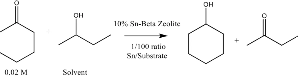
The reaction performed in order to test this catalyst is Meerwin-Ponndorf-Verley (MPV) reaction for transforming cyclohexanone in cyclohexanol with 2-butanol (figure 1.2):
Figure 1.2: scheme of MVP reactions
This is a standard reaction that has not a great importance from an Industrial point of view, but it is largely used in order to check if a catalyst is able to perform H-transfer reactions. Hence, this is the starting point to develop catalyst able to perform the glucose-fructose isomerisation that instead has a great importance nowadays in order to exploit renewable sources.
The main issues that Hammond group has found in development of this material are two:
the reproducibility is not high, in fact sometimes changing the operator the catalysts have different performances, this probably is caused by the a different application of strength that could disperse the source of tin differently, and so different loadings of tin are incorporated in the silanol holes
Has been noticed that increasing the loading of tin above 8% the incorporation is difficult because the tin tends to aggregate as SnO2 during the calcinations, so it could
be a good achievement to find a synthesis route that disperse better the source of tin preventing the agglomeration during the calcinations, allowing higher value of incorporate tin5.
11
2. Introduction
2.1 Heterogeneous catalysis
One of the most important fields of chemistry from an industrial point of view is Catalysis; this subject is interested in the development of catalytic materials that allow to carry out reactions with higher constant rate or with a better selectivity. It is so easy to understand why catalysis is really important for environment issues, in fact improving the performances of a reaction is possible to get better the whole Industrial process and so for example have less waste from by-products that could be harmful for the nature and can be eliminated with a new catalytic material. Indeed development in catalyst are also important because they can permit to change the raw material of a reaction: in the last 20 years a lot of efforts have been done to change the substrate for a huge number of productions, that were used to be done from petroleum. Nowadays instead, renewable sources of energy as biomass are exploited in order to have Green Processes respectful for the environment. These are only a few example of what catalysis represent for improving the efficiency of chemical processes in the world, but are already useful to understand the extreme importance of the research in this field of chemistry.
Exploring deeper catalysis is important to explain that we have basically two kind of catalysis: the homogeneous catalysis (where the catalyst and the substrate are dispersed in the same phase) and heterogeneous catalysis (where the catalyst and substrate are in two or three different phases). It is difficult to say which is the best in terms of costs and performances, it might be correct to say that this two kind of catalysis are used depending at the process requests and issues. Anyway it is easy to say which are their advantages: homogeneous catalysis permits a great interaction with the particles of the substrate and the catalyst and so it is possible to have mild reaction conditions, the main problems of this catalysis are about the separations of the catalyst and its recycle, in facts being the two components in the same phase it is much more expensive to separate them; otherwise if they were in different phases, as in heterogeneous catalysis, downstream processes would be much easier. However, heterogeneous catalytic materials have problems about mass transfers from the substrate phase to the catalyst and because of this; the conditions of reaction have to be harsher.
This simplicity in the downstream processes of heterogeneous catalysis is its strong point, in fact the 80% of catalysts in the world are heterogeneous, but it is important also to study the
12
synthesis processes for this catalysts, because it is important have new catalytic material that permit to carry out new environment respectful processes but it doesn’t make sense if in order to do that catalyst harmful and dirty synthesis are used. A multitude of technique are exploited to synthesize catalysts and sometimes the mechanisms that take place in them are not well understood and so it is important to improve the knowledge about them considering how huge is their production.2.
2.2 Standard preparations of the catalysts
Solid catalysts are highly sophisticated products derived from chemicals by several different procedures.
The catalytic properties of heterogeneous catalysts are strongly affected by every step of the preparation and from the quality of the raw material, but different method can be applied even for the same catalyst, thus gives an idea of how much is complicate and sometimes unknown what is happening during the preparations at these kind of materials. Anyway despite the complexity and the multitude of the methods it is possible to indentify some unit operations that present some analogies from one catalyst to another one and can be described in a general way2:
Chemical and physical transformations taking place in the synthesis
The scientific laws that rule this kind of transformation ( most of the case from inorganic chemistry)
Variables operations such as Temperature, pressure, pH, concentration etc Characteristic of the product after the synthesis
Type of required apparatus
Al the methods that will be discuss later present almost all this kind of operations, that are a good general guide of what implies the synthesis of a catalyst. However if the methods change as function of the material that we want to build up it is also important to figure out and classify the kind of heterogeneous catalyst with respect to the preparations procedure3,4:
1) Bulk Catalyst and Supports: bulk catalysts are mainly composed of all active phase, such as the Pt/Re net used for the oxidation of NH3 to NO. Supports, prepared by
13
similar procedures, are usually oxides on which active phase is deposed in order to perform the reaction. Often these materials have some activity on their own (Al2O3, TiO2, SiO2...)
2) Impregnated catalyst: are usually obtained from preformed support by impregnation with active phase.
3) Mixed-Agglomerated Catalyst: they are obtained by mixing the active substance with a powdered support or a support precursor and then agglomerating the mixture3.
2.2.1Precipitation and Co-precipitation
This way of synthesis is based on the precipitation of a solid from a liquid phase; this could happen for physical ways (such as increasing the temperature or for solvent evaporation) or could be due to a chemical process (addition of acids and bases or using complexes agents). This method consists basically of three moments.
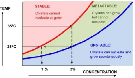
The first is Supersaturation: in this while the concentration of the precursors of the catalyst have an higher concentration then their maximum solubility, this metastable phase precedes the precipitation and can be caused by a changing of pH, a decreasing of temperature or the with the adding of an anti-solvent . This moment is really important in order to decide the particle size that will be precipitated; in fact increasing the supersaturation a faster Nucleation will take place. This is the second crucial moment of the precipitation process, in this moment nuclei of precipitate are formed in solution and their number depends on how much is high the supersaturation value. With a high supersaturation rate, more nuclei are formed in solution and so smaller particles are formed; this could not be spontaneous and so sometimes seeds of precipitations are added to the solution. The last moment is the Growth of the nuclei: in this moment the size of the nuclei growths, and so it is possible to have the dimension control. It is possible to build some graphs in temperature vs concentration for each system, where can be identified some the condition of solubility of the system (figure 2.1)4.
The difficult task of this process is obtaining high supersaturation values because the natural evolution of the system toward a decrease of supersaturation by nucleation of solid particle and consumption of the reagent, indeed high supersaturation value gives some problem about the mass and heat transport rate that bring to non-homogeneous precipitate respect to the size and structure.
14
Figure 2.1: The solubility and supersaturation curves of precipitating component material4
In the synthesis of multicomponent system the mechanism is even more complex. In coprecipitation in fact is really difficult to have a good macroscopic homogeneity, thus is caused from the differences in solubility of the different species to precipitate. Generally after the formation of the precipitate hydrothermal treatment are necessary in order to transform the structure from amorphous to crystalline with improved thermal stability and surface area acidity4.
These kinds of catalysts are the most diffused because this method is relatively simple, it is possible to control the size of the precipitate and the costs are not so high for industrial application. The most used catalysts are the hydroxides and carbonates that have a really low solubility but high solubility of the precursors, known structure and usually the doesn’t give environmental problem during the calcinations3.
15 2.2.2 Impregnation
The impregnation method is widely used in order to prepare catalyst composed of noble metal on supports, and it consists in the mixing of a solution of precursor of the metal and the support as solid; this method is divided in three steps3:
1) Contacting of the support with the impregnating solution for a certain period of time 2) Drying the support to remove the imbibed liquid
3) Activating the catalyst by calcinations, reduction or other appropriate treatment
These are the topic moments of the synthesis but we have two kind of impregnations in which this phases can be recognized. The first is the wet impregnation, here an excess of solution is used; after a certain time the solid is separated from the solution, and the excess solvent is removed by drying. The amount of the active precursor mounted onto the porous carrier, its concentration profile within the carrier grains, and its chemical environment on the support surface depend significantly on the conditions during these first two steps in catalyst preparation. Then the laws and parameters that rule the loading of active phase on the support are basically the mass transfer that is possible in the pores of the support, the concentration of the precursor in the solution and the adsorption isotherm which describes the binding energy of the precursor on the support surface. In figure 2.2 is possible to see how this process is carried out in an industrial implant3.
Figure 2.2: wet impregnation process3
Bucket Conveyor Drip Chute Bucket Drive Wheel Impregnating Basin Impregnating Solution Feed Bin Bucket Filter To drying Tipper
16
The second way to carry the impregnation out is through incipient wetness impregnation, in this way repeated applications of solution are used. A more precise control is achieved with this technique. The support is contacted with a solution of appropriate concentration, corresponding in quantity to the total known pore volume or slightly less. This operation can be performed continuously as in figure 2.3. The catalyst is kept in motion in a rotating cylinder or drum, and is sprinkled as required with a solution of salt by sprayers. The disadvantage is the poorer distribution of the precursors that bring to an inhomogeneous deposition of the active phase on the support.
The limit of this method is obviously the solubility of the precursor in the solvent, in order to avoid that it is possible to use two strategies: the easier way is drying the catalyst and then repeat the process of impregnation, but this obviously brings to higher costs and longer time of production. The other possibility is to increase the solubility of the precursor increasing the acidity or others parameters, the problem of this route are the damages that the support could undergo for the extreme conditions of the treatment4.
Figure 2.3: incipient wetness process3
Impregnanting Solution
Spray Header
Support to be impregnated
17 2.2.3 Gelation and Floculation
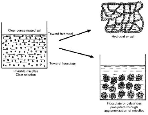
Gelation and flocculation are two catalyst way of synthesis that can be carried out by hydrophilic colloidal solution of the catalyst precursors; these are formed of micelles that remain separated because of electrical charges on their surface and in surrounding solutions. This kind of solutions can be obtained via chemical reactions of polymerization and polycondensation. The reticulation of these micelles forms the hydrogel, a three dimensional network that imprisons molecules of water. This point of the process is called gelation and it depends from many features as pH, temperature, concentration and ionic strength (Figure 2.4 is possible to see the mechanism of gelation and flocculation).
Figure 2.4: schematic mechanism of flocculation and gelation3
These gels can be dried by simple evaporation of the solvent, but evaporating the solvent in the pores of the material it is possible to provoke at the pores shrinkage with a concomitant reduction of surface area. The mechanical forces due to the retreating water menisci in the pores cause this; the easiest way to avoid that is try to replace water (the most used solvent) with another one that is characterized by a lower surface tension. This should prevent the shrinkage of the pores during the drying or of evaporation of the solvent.
Other two ways are possible in order to prevent the breaking of the structure in the evaporation phase: the first is by formation of an Areogel, this method carries out the drying of the solvent by supercritical extraction. For this reason, this method needs for high
18
temperature and pressure in order to transform the liquid into the pores of the material in a supercritical fluid that does not present a so high surface tension to break the material’s structure.
The second method to perform this synthesis by the formation of a Cryogel, that way exploits the freezing and the sublimation of the solvent in which is dissolved the gel4.
The flocculation of a sol can be obtained through the neutralization of the micelles charges (Figure 2.4). The final surface area of the solid depends on the original micelle size and also on the drying conditions.
2.2.4 Crystallization and Hydrothermal treatment
Crystallization is widely exploited in the preparations of homogeneous microporous solids; a class of monophase crystalline solids in which the active phase is distributed uniformly. When these kind of operation are carried out in water at 375 K the conditions are designed as ‘’hydrothermal’’; this has proven to be the most efficient way to produce these microporous materials.
Hence for hydrothermal transformations are considered all the modifications of precipitates, gel or flocculates induced by temperature, under aging or ripening in the presence of mother liquor and they usually involves textural or structural modification of the solid that can be summarized in:
1) Small crystals → Big crystals
2) Small amorphous particles → large amorphous particles 3) Amorphous solid → crystalline solid
4) Crystal type ‘’A’’ → Crystal type ‘’B’’ 5) High porous gel → low porous gel
All this transformations follow the laws of thermodynamic and thus proceed in a direction corresponding to a decrease in free energy of the system4.
This method of catalysts synthesis is exploited also to produce the Zeolite: this is a crystalline porous material made up by Silicates (SiO4) and alluminates ions (AlO4-) polymerized
together in a uniform structure. The synthesis of this material usually passes through sol-gel dissolution of the ions that under hydrothermal treatment crystallize in the wanted kind of
19
Zeolite. Nowadays several zeolite structures are known and they are exploited in a lot o chemistry field for their great activity, selectivity and resistance at the reactions conditions. For example zeolite are widely exploited in the fluid catalytic cracking of petroleum, It is widely used to convert the high-boiling, high-molecular weight hydrocarbon fractions of petroleum crude oils to more valuable gasoline, olefinicgases, and other products. This process is carried out at very high temperature and the raw material is not clean, for that are used zeolites as a catalyst; in fact, they are suitable materials to resist and be regenerated easily in this conditions.
2.3 Mecchanomechanical synthesis of catalysts
Previously the most exploited ways to produce heterogeneous catalysts have been described; it is possible to understand how complicated and fragile methods they are.
In facts, they depend strongly from a huge number of conditions as pH, temperature, concentration, stirring etc...
These features have a great effect on the final products and a changing in one of them could compromise the result of the synthesis, these problems obviously generate high cost and the need of sophisticated apparatuses. Indeed high amounts of solvent are usually required in these kind of synthesis, that is obviously a problem as a process point of view because it is necessary to have an efficient downstream separation, but it is also a problem for the environment because the solvent will be polluted by all the chemicals involved in the process, and so it has to be treated before to be disposed5.
Considering that this synthesis last usually days, the researchers working in this field of chemistry are looking for developing new kind of synthesis that can improve the preparations of catalysts reducing the costs and simplifying all the processes.
It is so easy to understand why many groups are recently working on the developing of mechanomechanical synthesis of heterogeneous catalyst.
2.3.1 Mechanochemistry: general features
‘’ Mechanochemistry is a branch of chemistry dealing with the chemical and physicochemical changes of substances in all states of aggregation due to the influence of mechanical energy’’; this is the first definition of mechanochemistry given in 1887 by Ostwald8.
20
When energy is added to a solid substance by mechanical treatment such as crushing, grinding, rolling or impacting, the deformation and subvision of the solid occur simultaneously with rapid increase of the surface energy due to the increase of surface area. The mechanical energy added to crystal particles during grinding has a great effect of the crystal structure of the particles and the changing of the physicochemical property of the solid due to the mechanical action is thus call “mechanochemical effect”6. Different kind of
devices are used to transmit this mechanical energy, one of the most used machine industrially exploited is the Ball Mill (Figure 2.5)
Figure 2.5: Example of Industrial Ball7
Nowadays it is increasing the interest for this field of chemistry for different kind of applications, since inorganic chemistry to the most sophisticated organic synthesis.
This technique in fact, even if it works by complicated mechanisms, permits to carry out processes in solvent-free conditions that have a great gain in terms of implant, costs but especially for developing green-sustainable processes. From an industrial point of view, this kind of operations are not properly solvent-free, in fact they are use to be carried out in wet conditions in order to control the emission of the fine dust and improve the mixing, but in any case they allow to reduce substantially the volumes and amount of solvent.
21
For this incredible potentialities researchers are trying to understand what is happening in this complicated mechanichal treatment and in particular applying this concept to all kind of chemistry: organic chemistry in facts employs mechanochemical treatment on cellulosic materials, whose molecular chain can be degraded by mechanical comminution; but also in organic synthesis this kind of technique is becoming really important because has been studied that some organic reactions present a different activity and selectivity if carried out with a solvent-free mechanical synthesis, instead of a normal reaction in solvent8.
On the other hand, what is more important for the aim of this work is the applicability of these techniques in Inorganic Chemistry; in fact, many mechanochemical operations are actually exploited to synthesize or modify some inorganic materials8.
2.3.2 Mechanochemistry and Inorganic Materials
Resuming the effect of this treatment on inorganic materials is possible to identify these four generic ones8:
Generations of new large surfaces Formation of point defects
Phase transformation in polymorphic materials Chemical reactions
In most of the works, the cause for the mechanocemical effects is not qualitatively discussed in terms of the energetic conditions of collision. However these phenomena have been explained in terms of near surface dislocations and slip, and highly localized transient ‘’hot spots’’. For example in the high speed rolling of aluminium, temperatures close to the melting point of the metal are generated in the vicinity of the line of contact in the rolling operation, at these temperatures the higher mobility of atoms in the near-surface regions, near-surface dislocation, and oxidation are realities.
This explains why some reactions that take place usually in solution can be carried out also with this method in fact in inorganic synthesis such solid state reaction are possible only under three conditions9:
22
1) The reaction should be thermodynamically feasible from the consideration of Gibbs free energy changes
2) The two reacting species should be in intimate contact
3) The temperatures should be typically above the 40% of the melting point of the inorganic solid.
These temperatures are empirically defined to be between 0.4Tm and 0.5 Tm (Tm is the fusion
temperature), usually after 0.3 Tm the mobility of surface defects becomes significant and
increasing over this point the mobility of the species on the surface is possibly to carry out reactions on the solid material7.
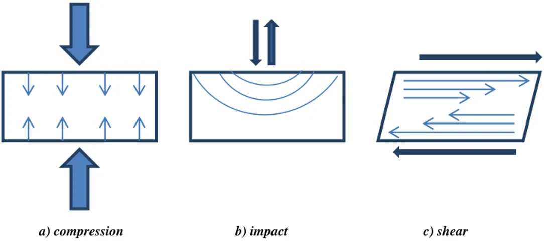
Then changing point of view on the physical properties of the material treated in the communiting device, it is possible to imagine many types of forces occurring when solids are ground but the most common forces that particles undergo are compression, impact and shear (Figure 2.6). Finely ground particles with a narrow size distribution are produced when the applied stresses are mainly due to shear. It is difficult instead to produce fine particle when only compressive stresses are used, and the width of the size distribution obtained tends to be broadened. Impact forces instead give intermediate results between shear and compressive forces; obviously is not possible to apply selectively one kind of stress or another one, but it is possible to have a predominant stress as function of the device exploited6.
Figure 2.6: The most common forces applied on the materials by mechanical treatment5
23 2.3.3 Ball mill as grinding device
Of particular interest in this field is the exploitation of the ball mills as device to treat the materials, this device is composed of a capsule in which is located the solid and the balls, that will grind the powder during the movement of the capsule. A multitude of different type of ball mills are available but all of them have general points in common, in fact this kind of device is generally use to apply impact stress that, as explained before, is a middle way between the shear and the compressive stress, making so really interesting its effects on materials5.
Figure 2.7: schematic illustration of ball mill spheres7
In this apparatus the particles caught between the colliding balls (or between the ball and the capsule) experience high stress; further, most of the collision energy is applied over a small contact area, represented by the surface contact between the spheres, that makes the applied energy per area extremely high (Figure 2.7). Indeed considering the high velocity of the balls in the capsules this strength is applied for a short time, and the time of relaxing is short as well leading to very high stress gradient. All the factors are conductive to giving highly localized and transient hot spots, where the temperatures are high enough to cause thermally induced atom mobility in the near surface region in and around the contact area between the colliding balls, leading to mechanochemical effects on the material9
24
2.4 Introduction to the Reaction involved in the work
In order to apply the mechanochemical synthesis we chose different material to study the answers of different supports to this kind of preparation, but it has been decided to apply this technique also for catalysts that were intended to work in two different field of chemistry. In fact, we chose to study the fluorination reaction to employ this catalyst mainly in production of fine chemical with high added value. Instead, the Meervein Ponndorf Verley (MVP) H-transfer reaction was chosen as test reaction of the more industrially important glucose-fructose isomerisation. This reaction is studied to convert glucose in fructose from which is possible to synthesize a huge number of molecules; hence, this catalyst is intended to work in bigger market, near to the bulk chemicals10.
2.4.1 Glucose-fructose isomerisation and Sn-β Zeolite
Nowadays is of great interest the exploitation of renewable sources of raw material, especially if they are second generation sources ( that means they are not in competition with food resources), hence biomass are playing an important role in this revolution of chemistry, but their utilization is not so easy to execute11.
Biomass is a complex material made up different parts as lignin, cellulose, and hemicelluloses; between them, the easiest material that can be used as source of raw molecules is the cellulose that is a polymer made up by β-glucose monomers that in this way can be easily obtained.
Glucose is an important raw material to obtain a huge number of molecules of great interest for Industrial chemistry as Adipic Acid (use in the synthesis of nylon), Lactic acid (exploited in the synthesis of biocompatible polymers), Methacrylic acid (used as well in polymers synthesis) and Furanic cycles11 (figure 2.8).
25
Figure 2.8: examples of fructose exploitation as platform molecule11
A lot of other molecules can be synthesized by glucose but furanic cycles, for example Hydroxy-methyl Furfural (HMF), are having a great success as platform molecules.
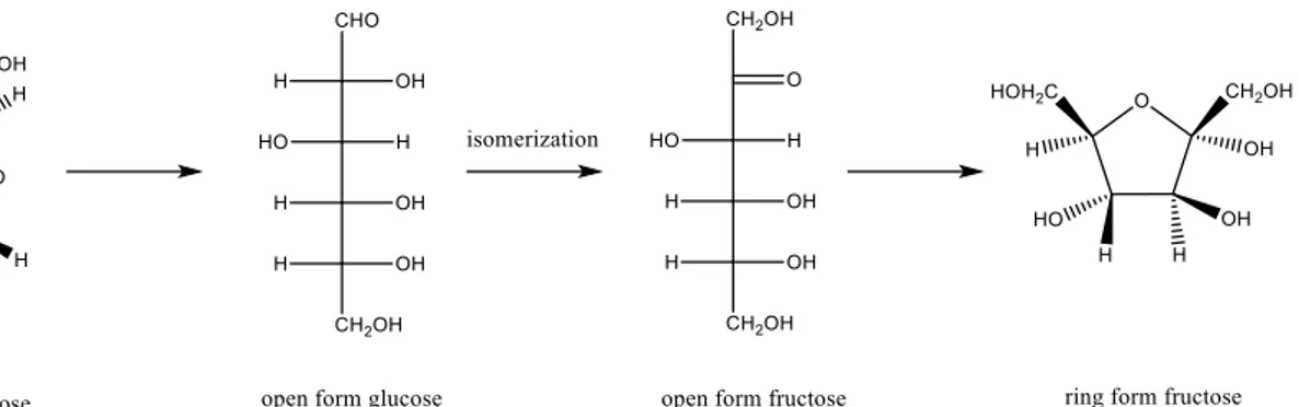
Hence their synthesis is deeply studied and all of this kind of cycles come from Fructose, that is obtained by glucose via isomerisation (Fig 2.9), this is not a banal reaction in fact was used to be carried out with enzymes that have great efficiency and selectivity for this reaction. On the other hand, their problem is that enzymes are complex systems that have to work in restricted conditions of temperature, pH and pressures10.
26
These issues added to the high costs of enzymes made difficult their exploitation in processing huge amounts of glucose: so many efforts have been spent in order to find an inorganic catalyst that can perform this reaction in larger range of conditions but also with fewer problems from a separation point of view.
Figure 2.10: typical structure of β-Zeolite12
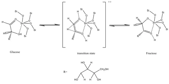
Tin-containing silicates have recently emerged as a new class of inorganic solids with Lewis acid character capable of activating carbonyl functional groups in the presence of water. The pioneering work of Moliner at al13 showed that Sn-β Zeolite (Figure 2.10) is highly active in
Meerwin-Ponndorf-Verley (MPV) reaction; this is a family of H-transfer reactions that can be used to test the effectiveness of this catalysts. The same, but intramolecular, H-transfer reaction in fact can be exploited to perform the isomerisation glucose-fructose. The mechanism of action of this catalyst is shown in Figure 2.11
27 2.4.2 Synthesis of Sn-β Zeolite
Tin-β Zeolite is actually produced by hydrothermal crystallization process in which is used a reaction mixture prepared by combining sources of tin, silicon, a templating agent a fluoride source and water. In this preparation method are used as reactive tin tretrachloride and fluoric acid as source of tin and fluoride respectively, obviously these are not the best reagent as green chemicals, in fact fluoric acid is extremely toxic and has to be avoided in all the processes and tetrachloride releases chloridric acid that is highly corrosive, harmful for the workers and its acidity ruins the implants apparatus. Indeed 40-50 days are necessary to crystallize the material that is a very long time that enhances the costs of production (Figure 2.12)14.
For this reasons many efforts are being spent to discover new way of synthesis for the Sn-β zeolite that can decrease the costs and safety of the process.
Figure 2.12: comparison between hydrothermal and mechanochemical synthesis
Actually Hammond group has developed a new way of synthesis for this catalyst by mechanochemical treatment, this method consist in a solid state incorporation (SSI) of the Tin
28
exploiting as source of tin the tin (II) acetate. The SSI method is divided in two fundamental steps4:
De-Alumination of β-zeolite by acid treatment with a solution of HNO3
Grinding of De-Aluminated zeolite with the source of tin and calcination of the mixture
In the first step, the aluminium is removed from the structure leaving so some vacations between the silanols group (silanol holes). Then during the grinding the tin(II) acetate is dispersed in the solid and then is incorporated in this holes during the process of calcinations in air that permits to burn the acetate anion of the salts (figure 2.13). If the tin is well incorporated it will full the silanol holes instead of aluminium, otherwise it will form some tin (IV) oxide agglomerates that are not useful for carrying out the H-transfer reaction.
Figure 2.13: Solid-state incorporation mechanism
29 2.4.3 Fluorination: industrial importance
Carbon-fluorine bond formation is playing an ever-growing role in the synthesis of chemicals and pharmaceuticals, because the introduction of fluorine atoms alters markedly the physical, chemical, and biological properties of the organic molecules. Hence, a lot of groups and researchers are committed to developing new way to construct C-F bond15.
The main applications for this fluorination reactions compounds are in the synthesis of drugs where fluorine atoms can alter the lipophilicity and metabolic stability, which can enhance the bioavailability and efficacy of a drug compound. In 2006 in fact the percentage of the drugs containing fluorinated structures reached approximately 20% of the total market, and in agrochemical market up to 30% of the compound in general use contain fluorine atoms in the main structure16.
Indeed fluorine it is widely exploited in the polymer industries where it is used to functionalize monomers to synthesize chemicals-resistant polymers such as Teflon ( polytetrafluorethylene ). Then it is used also for the synthesis of compounds for molecular emission tomography (PET) imaging that is a technique exploited for cancer diagnosis. The most produced compound for this scope is Fluorodeoxyglucose (Figure 2.14), that is a modified glucose molecule with the –OH group on the second atom of carbon that is substituted by an 18F atoms17-18. This modification does not allow the metabolisation of this molecule that is accumulated in the tissues, and will be absorbed only by cells that have a fast metabolism and therefore need a large need of glucose to be operative, such as the brain, kidneys and rapidly multiplying tumours.
Despite fluorine is abundant in nature there only a small number of organic compounds occurring naturally, also for this reason the development of facile and versatile fluorination method are essential.
30 2.4.4 Reactants and Processes
Reactants for carrying out fluorination reaction can be divided in two main categories: nucleophilic and electrophilic fluorinating agents, several examples of this kind of reactants are reported in table 2.119.
Nucleophilic fluorinating agent Electrophilic fluorinating agent
Alkali metal fluoride N-fluoropyridinium salts Tetraalkylammonium fluoride Selectfluor® and derivates
Table 2.1: Reagent exploited as fluorinating reactants
Nucleophilic reactants are exploited in the fluorination of hydrocarbons having a leaving group that can be easily substituted with the fluoride ions supplied by the fluorinating agent. In industries, this kind of reaction often exploits ion exchange of halogen (Halex process) to replace one halogen atom in the molecule (typically chlorine) with another one that in this case is fluorine20.
In order to perform this process are required electron-withdrawing groups ( EWGs ), that are able to activate the halogen atom in the molecule, that so can be substituted by halide ion supplied by the metal halide ( usually employed as source of new halogens in this reactions) . Unfortunately this reaction has several drawbacks that makes this synthesis really costly, in facts in order to activate the halogen atom the EWGs groups required are really strong and the temperature are usually up to 200°C, high temperatures are not only a problem for the energetic costs and implants materials, but usually they cause side reactions that decrease the hypothetic performances of the process.
For this reasons it is also of great importance the study of electrophilic reactants as fluorinating agents, but with them, it is not simple to get reactions to occur producing the specific hilarity required. In order to improve the regioselectivity and enantioselectivity for this reaction has been exploited the use of nucleophilic organometallic reagent to react with the electrphilic fluorinating agents21. Otherwise is also studied the exploitation of transition metals as catalyst to improve the performances of this fluorinating agents22.
31 2.4.5 SelectFluor® and Silver catalyst
Selectfluor® is an electrophilic fluorine source firstly described in 1992 and since then become one of the most widely available and often used commercial sources of fluorine for fluorination reactions. SelectFluor® is a trademark of the company ‘’Air products and Chemicals’’ it has been projected to be a safe electrophilic fluorinating agent but at the same time with a strong fluorination effect. This reactant has been studied for different reactions and with many catalysts, of great interest is the reaction of decarboxylative fluorination promoted by AgNO3 (20% mol) in homogeneous solution and carried out in mild condition,
this reaction is performed in a mixture water-acetone in order to dissolve catalyst and the SelectFluor® (two equivalents)23.
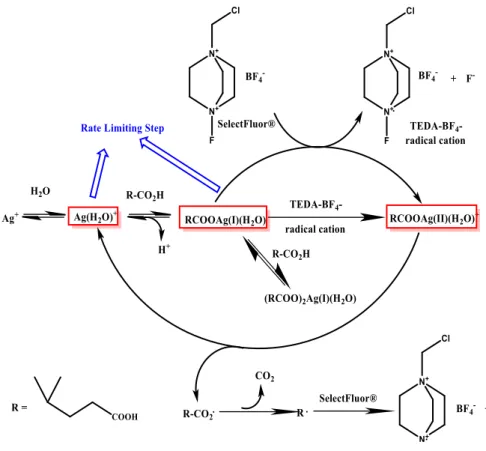
The proposed mechanism for this reaction on 2,2 dimethyl glucaric acid is shown in figure 2.15.This is a radicalic reaction, that is highly selective for the substitution of the carboxylic group linked to the tertiary carbon, that thanks to the influence of the vicinal methyl-group stabilize better the incipient radical formed in the intermediate of reaction.
Figure 2.15: mechanism of Fluorination Reaction for 2,2 Dimethyl glutaric acid by computational work of X.Zhan24
32
Recently Hammond group has developed a new heterogeneous route for this kind of fluorination, in fact reactions performed with SelectFluor® have been usually carried out in homogeneous solution, this kind of condition brings to high cost for the product purification from the metal dissolved in solution as catalyst, instead with the heterogeneous conditions the separation is much easier and the recycling of the catalyst could be much more convenient. Firstly the heterogeneous catalyst was synthesized by sol-gel immobilisation where silver-nanoparticles were deposited on titania; then ,thanks to the mechanistic study in Figure n.11 has been demonstrated how the reaction doesn’t need for the presence of metallic silver to carry out the reaction, but Ag (I) and Ag(II) are the only active species24. Hence, from this achievement a solvent-free synthesis has been developed to produce a catalyst of silver (I) oxide deposited on Titania, simply by grinding the support with the oxide powder.
33
3. Experimental Part
3.1 Chemicals
In Table 3.1 is possible to find the chemicals exploited for the synthesis of the titania and silver catalysts, and their subsequent catalytic reactions.
Chemical
Brand
Purity
TiO2 aeroxide P25 Aerosil®
>99%
AgO2 Sigma Aldirch®
>99%
2,2 Dimethyl Glutaric Acid Sigma Aldrich®
98%
Succinic Acid Sigma Aldrich®
>99%
K2CO3 Sigma Aldrich®
>99%
Table 3.1: Chemicals used in fluorination reaction
In table 3.2, the chemicals used in the synthesis and catalytic reactions of Sn β-zeolite are reported.
Chemical
Brand
Purity
Zeolite β (Si/Al=38) Zeolyst®
>99%
Sn(II) (acac)2 Sigma Aldrich®
>99%
Nitric Acid Sigma Aldrich®
70%
Cyclohexanone Sigma Aldrich®
99%
Cyclohexanol Sigma Aldrich®
99%
Biphenyl Sigma Aldrich®
>99%
2-Buthanol Sigma Aldrich®
>99%
34
3.2 Catalyst synthesis
3.2.1 Synthesis of 10% Tin β-Zeolite
Commercial zeolite Al-β (Zeolyst, NH4- for, SiO2/Al2O3) was dealuminated by treatment in
HNO3 solution (13 M HNO3, 100°C, 20h, 20 mLg-1 zeolite ). The reaction mixture was
washed extensively with water (around 500 mL per g of catalyst), and dried overnight at 110°C in an oven. The solid obtained was later grinded with pestle and mortar to get a homogeneous powder, after which period Solid State Incorporation was performed by a modified procedure of ref5 using a mixer mill (mixer mill M400, Retsch). The appropriate amount of tin (II) acetate was added at the zeolite and the sample was grinded in the mixer mill for 20 minutes at various frequencies (3 – 30 Hz). The amount of metal to use in the catalyst synthesis was calculated with the equation n.1.
𝒘 𝒘% =
𝒎𝒂𝒔𝒔 𝒐𝒇 𝒎𝒆𝒕𝒂𝒍 (𝒈)
𝒎𝒂𝒔𝒔 𝒐𝒇 𝒔𝒖𝒑𝒑𝒐𝒓𝒕 (𝒈)∗ 𝟏𝟎𝟎
Equation n.1: calculation to find out the metallic loading in a supported catalyst
Following this procedure, the sample was heated in a combustion furnace (Carbolite MF12/38/400) to 550°C (10°C min-1 ramp rate) first in a flow of N2 (3h) and subsequently air
(3h) for a total of 6h. Gas flow rates of 60 mL-1 were employed at all the times. The sample was held horizontally in an alumina combustion boat (10 mL capacity), and a quartz tube was used to seal the sample environment and permit gas flow.
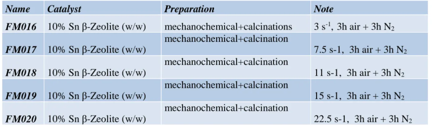
The catalysts synthesised by this protocol are reported in Table 3.3.
Name Catalyst Preparation Note
FM016 10% Sn β-Zeolite (w/w) mechanochemical+calcinations 3 s-1, 3h air + 3h N2
FM017 10% Sn β-Zeolite (w/w) mechanochemical+calcination 7.5 s-1, 3h air + 3h N2 FM018 10% Sn β-Zeolite (w/w) mechanochemical+calcination 11 s-1, 3h air + 3h N2 FM019 10% Sn β-Zeolite (w/w) mechanochemical+calcination 15 s-1, 3h air + 3h N2 FM020 10% Sn β-Zeolite (w/w) mechanochemical+calcination 22.5 s-1, 3h air + 3h N2
35 3.2.2 Synthesis of silver (I) on Titania catalyst
The silver(I) supported on titania catalysts were synthesized with the Mixer Mill (mixer mill M400, RetschTM) according to the following procedure. Silver (I) oxide (>99%, Sigma
Aldrich) was added to the Titania Aeroxide P25 (Acros Organics) in order to have a catalyst with a metal loading of 1wt.%, as calculated by equation n.1. The mixture was grinded for 20 minutes at different frequencies (3 – 30 Hz). Then samples were subsequently heated in a combustion furnace (Carbolite MTF 10/25/150) at different temperatures. The synthesized catalysts are reported in table 3.4.
Name Catalyst Preparation Note
FM001 1% Ag/Titania (w/w) physical mixture 10 minutes high intensity
FM002 1% Ag/Titania (w/w) physical mixture 20 minutes high intensity
FM003 1% Ag/Titania (w/w) physical mixture 40 minutes high intensity
FM004 1% Ag/Titania (w/w) physical mixture 20 minutes low intensity
FM005 1% Ag/Titania (w/w) FM001+calcination 150°C, 3h air atmosphere
FM006 1% Ag/Titania (w/w) FM001+calcination 200°C, 3h air atmosphere
FM007 1% Ag/Titania (w/w) FM001+calcination 250°C, 3h air atmosphere
FM008 1% Ag/Titania (w/w) FM001+calcination 300°C, 3h air atmosphere
FM009 1% Ag/Titania (w/w) FM001+calcination 350°C, 3h air atmosphere
FM010 1% Ag/Titania (w/w) FM001+calcination 400°C, 3h air atmosphere
FM011 1% Ag/Titania (w/w) mechanochemical 3 s-1 of frequency
FM012 1% Ag/Titania (w/w) Mechanochemical 7.5 s-1 of frequency FM013 1% Ag/Titania (w/w) mechanochemical 15 s-1 of frequency FM014 1% Ag/Titania (w/w) mechanochemical 22.5 s-1 of frequency FM015 1% Ag/Titania (w/w) Mechanochemical 30 s-1 of frequency
36 3.2.3 Mixer Mill MM400 (RetschTM)
In order to perform the target work of this project, a milling machine was employed, in order to allow all the catalysts preparation to be performed with a high degree of reproducibility and under a wide range of experimental conditions. The machine employed was a Mixer Mill MM400 from Retch (Figure 3.1).
Figure 3.1: Mixer Mill MM400 (RetschTM)
This machine is composed by two arms that are each attached to one steel jar (25mL). The sample is located within this capsule, along with a steel ball of 0.7 cm diameter.
In this machine, the grinding jars of the MM 400 perform radial oscillations in a horizontal position. The inertia of the grinding balls causes them to impact with high energy on the sample material at the rounded ends of the grinding jars and pulverizes it. Also, the movement of the grinding jars combined with the movement of the balls result in the intensive mixing of the sample; and the important thing is that is possible to regulate accurately the oscillation of the jars in order to have a reproducible energy in the grinding. The Mixer Mill MM400 can cover from 3s-1 to 30 s-1 of oscillation frequency with steps of 0.1 s-1, so a huge number of frequencies can be explored reproducibly.
37
3.3 Catalytic Tests
3.3.1 Fluorination Reaction
The fluorination of 2,2-dimethyl glucaric acid (figure 3.2) was performed with a 10 mL round bottom flask at room temperature under stirring (700 rpm), every reaction has been performed with these reaction parameters:
Figure 3.2: Fluorination reaction scheme
SelectFluor®: 0.1417 g (0.4 mmol) K2CO3: 0.032 g (0.231 mmol)
Silver (I) oxide on titania (1wt.% loading of Ag) : 0.100 g 2,2-Dimethyl glucaric acid solution (2.5 mM) : 4 mL Atmosphere : N2
Temperature : Room temperature Stirring : 700 rpm
Time : 2 hours
The reaction was started by adding a solution of 2,2-Dimethyl glucaric acid (2.5 mM) by syringe. During the reaction, samples of 0.1 g were withdrawn periodically for analysis. Prior to injection into the HPLC, samples were centrifuged and diluted to 0.5 mL by addition of a solution of 1,4-succinic acid (3 mM) taking note of the exact mass of sample that was diluted. Since the standard is not internal (it was used to react instead of the 2,2 Dimethyl Glucaric acid) all aliquots of the reaction solution and external standard were weighed in order to
38
produce trustworthy data. These sample were analysed by high-performance liquid chromatography (HPLC, Agilent 1220 Infinity LC) using a column for acid separation (MetaCarb 87H 250 x 4.6 mm, Varian, at 60°C ) and a UV-Vis detector. The eluent was an aqueous solution of phosphoric acid (0.1 wt %) and the flow rate was 0.4 mL min-1.
During the recycle tests, reactions were performed at 30 °C in order to have reproducible data given that the room temperature during the summer months was unstable. Moreover, the time of reaction was kept shorter (30 minutes) to avoid as much as possible to leave the catalyst in contact with the pollutant chemicals in the reaction mixture.
Photoreactor reaction: The fluorination reaction was also performed in a photoreactor (PV
cell testing solar simulator 16S-300-002, Solar light ). The reaction conditions were identical to the non-photocatalytic tests (2.3.1) except the atmosphere was air (not N2) and the reaction
time was just ten minutes long). This experiment was exploited to test the 30 s-1 frequency of grinding in a photocatalysed reaction. Additionally, the blank reaction without catalyst was also performed under identical conditions, to check if SelctFluor® alone was active under the light source in the absence of a catalyst.
All the calibrations were done by the commercial reactants by Sigma Aldrich, only the product of the reaction (5-fluoro-4,4-dimethyl-5-oxopentanoic acid) was isolated by chromatography on silica and then calibrated with succinic acid as external standard.
Experiments to explore the homogeneous rate of the reactions: this reaction has been
performed in heterogeneous condition for the first time, so it is necessary to check if the catalyst has some leaching of Silver, and if this silver that will be homogeneously dissolved can carry out on its own the reaction. Two methods have been employed to measure that:
Leaching Analysis: in this analysis the normal reaction is performed and stopped after 10 minutes, the solution is filtered from the catalyst and then analyzed by MP-AES (Chapter 2.4.5) in order to measure the amount of silver leached from the catalyst. Hot Filtration: In this analysis, the fluorination reaction has performed as previously
explained, but the catalyst was filtered from the solution after 5 minutes (for catalyst FM012) and after 10 minutes (for catalyst FM013. It is important in this case not to mix the reaction mixture with air but maintain it under a N2 atmosphere, because the
reaction in air is much slower. Changes in conversion following removal of the solid catalysts were monitored in order to check if the reaction mixture is active after the
39
filtration or if it is stopped. This result gives an indication of how much the homogeneous silver leached from the catalyst can catalyse the reaction on its own.
3.3.2 Meerwein Ponndorf Verley transfer Hydrogenation-C6 Reaction
The MPV transfer hydrogenation of cycloheaxanone ( figure 3.3) was performed in a 50 mL two necked round bottomed flask equipped with a reflux condenser, which was thermostatically controlled by immersion in a silicon oil bath. The vessel was charged with a 10 mL solution of cyclohexanone in 2-butanol (0.2 M), which also contained an internal standard (biphenyl 0.01 M). The reaction was performed at 100°C13.
Figure 3.3: MVP-C6 Reaction scheme
The reaction was initiated by addition of an appropriate amount of catalyst, corresponding to 1 mol % of Sn relative to cyclohexanone. The solution was stirred at 800 rpm with an oval magnetic stirrer bar. Aliquots of reaction solution were taken periodically for GC-analysis and were centrifuged prior to injection into the GC (Agilent 7820, 25 m CP-Wax 52 CB). Reactants were quantified against a biphenyl (>99%, Sigma Aldrich) internal standard. These tests were used to analyze the catalysts synthesized with the Mixer Mill MM400 in order to find out if there was a maximum of catalytic performance corresponding to a frequency of grinding. This is a standard H-transfer reaction usually performed to check if the catalyst is effective in H-transfer reaction, hence it is usually the starting point in order to study the isomerisation of glucose to fructose.
The calibrations were carried out by commercial chemical by Sigma Aldrich with an internal standard (Biphenyl).
40 3.3.3 HPLC-analysis of Fluorination Reaction
In order to analyze the reaction mixture HPLC (High Performance Liquid Chromatography ) was exploited; a specific column ( MetaCarb 87H 250 x 4.6 mm) was necessary because in fluorination reaction is involved 2,2-dimethyl-glucaric acid and this column is specifically designed for organic acids, which are typically harmful to standard HPLC columns. The HPLC employed was an Agilent 1220 Infinity HPLC equipped with an autosampler, an oven to maintained at 60°C the columns located inside and with a variable wavelength UV-VIS (VWD) detector set at 210 nm and the flow has been set at 0.400 mL/min. The liquid-carrier was phosphoric acid (0.1 % wt) in ultrapure HPLC-water.
The calibration for the 2,2-Dimethyl-glucaric acid was carried out with the commercial chemical from Sigma Aldrich and the results are shown in Table 3.5 and figure 3.4
Chemicals Retention Time [min] Equation R2 2,2 –Dimethyl-glucaric acid 6.61 y = 0,5284x 0.9987 5-fluoro-4,4-dimethyl-5-oxopentanoic acid 9.01 y = 4,7378x 0.9983
Succinic Acid 5.02 internal standard
41
Figure 3.4: calibration of reactants performed with the HPLC
The analysis of the product of reaction ( 5-fluoro-4,4-dimethyl-5-oxopentanoic acid ) was much more complicated: the chemical was not available as commercial so it was necessary to isolate it via Silica-gel chromatography, but as we can see in the chromatogram (figure 3.5) the peak was not so easy to calibrate because it is quite broad ( retention time: 9.307 m).
Figure 3.5: chromatogram for the fluorination reaction from HPLC analysis
Verification that there were no other byproducts was achieved by F-NMR experiments that clearly shown as the fluorine atoms in solutions are due to the Select Fluor® peaks and to the product. Selectivity was calculated with the calibrations in Figure n.4 in order to check if there were important changes that could suggest the presence of a by-product.
Preparation of the sample: the withdrawn sample was centrifuged in order to separate the
solid catalyst from the liquid reaction mixture, 0.1 g of liquid were withdrawn and add in a 0 1 2 3 4 5 6 0 2 4 6 8 10 12 Cx/ Cst Ax/Ast
DMGA calibration
42
GC-vial containing 0.5 mL of Succinic Acid solution (3 mM). The vial is waved strongly and then injected in the HPLC.
3.3.4 GC-analysis of MVP-C6 Reaction
The MVP-C6 reaction has been analyzed by gas chromatography (GC), and a polar column was employed in order to separate all the required compounds (25 m CP-Wax 52 CB that is filled with a polyethylene glycol phase). The machine used was an Agilent 7820 equipped with an autosampler and a FID (Flame Ionization Detector ). The gas carrier was Helium and it was maintained with a flow of 3mL/min.
The analysis is performed checking the concentration of cyclohexanone and cyclohexanol, their calibration was performed with an internal standard (biphenyl) and all the chemicals were available from Sigma Aldrich. In table 3.6 and figure 3.6 are reported the calibration lines equations for the cyclohexanone and for cyclohexanol.
Chemicals Retention
Time [min]
Equation R2
Cycloheanone 14.2 y = 2,1716x 0.9957
Cyclohexanol 15.4 y =2,1907x 0.9955 Table 3.6: Results of Calibrations of the Reactants
43
Figure 3.6: Calibration line for Cyclohexanone and Cyclohexanol
Preparation of the sample: a sample of 0.100-0.150 mL is withdrawn from the reaction
misture and centrifuged to deposit all the catalyst at the bottom of the capsule, then about 0.1 mL of the liquid phase of the sample is added in a GC vial containing 0.300 mL of 2-butanol.
0 5 10 15 20 25 0 2 4 6 8 10
Calibration Cyclohexanone
C x /C st d Ax/Astd 0 5 10 15 20 25 0 2 4 6 8 10Calibration Cyclohexanol
C x /C st d Ax/Astd44
3.4 Characterization of the catalysts
3.4.1 Diffraction Ray-X analysis (XRD)
X-ray diffractometry (XRD) is a powerful technique widely exploited to study the properties of a solid sample.
This technique is useful to study:
The crystallinity rate of a particular solid or of its component Size of crystals
The kind of allotropic shape in the sample
Cell’s size and the kind of atoms of which is composed
The analysis is performed directing a collimated X-ray beam on the sample; this beam will be diffracted only in some particulars directions, depending on the crystal phase that is present in the sample. This diffraction is ruled by the Bragg rule:
𝑛𝜆 = 2𝑑 𝑠𝑖𝑛𝜃
In this equation 𝑛 is a whole number, λ is the wavelength of the incidence X-ray, 𝑑 is the distance between the atomics layers in a crystal, and 𝜃 is the angle of incidence. The intensity of the diffracted angle is measured as a function of the diffraction angle. Indeed is possible to estimate the size of the crystals of the sample thanks to this equation:
𝑑 = 𝐾𝜆 /𝑏𝑐𝑜𝑠𝜃
In this equation 𝑏 = √𝐵2− 𝛽2 ( B = the width of the peak at the half of its total height ), 𝜃 is
angle of incidence, 𝜆 is the wavelength of the incidence X-ray and K is a constant with a value about 0.9-125.
Every diffraction peak is linked with the Bragg law to an exact distance 𝑑 between the layers of the crystal lattice, these distances are typical of every crystal cell, and so it is possible to identify the phases that are in the analyzed sample.
Powder X-ray diffraction analysis was performed on PANalytical X’PertPRO X-ray diffractometer, with a CuKα radiation source (40kV and 40mA). Diffraction Patterns are
45
recorded between 6-55° at step size of 0.0167° (time/step = 150s). The scheme of the instrument is shown in Figure 3.7.
Figure 3.7 : Scheme of the XRD diffractometer exploited in the analysis
3.4.2 Surface area analysis
The surface area of a catalyst represent the ratio between the whole surface of the sample and its weight, it is usually expressed as m2/g.
This parameter is important because it is one of the main features that can describe a catalyst from a catalytic point of view. In order to measure this property of the sample a Quantachrome Autosorb has been employed. The surface area is recorded thanks to the amount of gas (usually N2 at 77K ) that is physically adsorbed as molecular monolayer, this is
possible knowing the diameter of the N2 molecule (0.162 mm2) because:
It is a spontaneous process
It has a really low rate of specificity and so all the surface is recovered and not only on specific sites
It is fast It is reversible
After a degassing phase, to push the gases and adsorbed component off from the catalyst surface, the sample is depressurized under vacuum and then N2 adsorption begins.