S H O R T C O M M U N I C A T I O N
Determining nonuniformities of core-shell nanoparticle
coatings by analysis of the inelastic background of X-ray
photoelectron spectroscopy survey spectra
Anja Müller
1,2|
Katia Sparnacci
3|
Wolfgang E.S. Unger
1,2|
Sven Tougaard
41
Department of Chemistry, Humboldt-Universität zu Berlin, Berlin, Germany
2
Surface Analysis and Interfacial Chemistry, Bundesanstalt für Materialforschung und -prüfung, Berlin, Germany
3
Department of Science and Technological Innovation, Università del Piemonte Orientale, Alessandria, Italy
4
Department of Nanophysics, University of Southern Denmark, Odense, Denmark
Correspondence
Anja Müller, 6.1 Surface Analysis and Interfacial Chemistry, Bundesanstalt für Materialforschung und -Prüfung, Berlin, Germany.
Email: [email protected]
Sven Tougaard, Department of Nanophysics, University of Southern, Odense, Denmark. Email: [email protected]
Funding information
EMPIR Participating States; European Union's Horizon 2020; European Metrology Programme for Innovation and Research (EMPIR), Grant/Award Numbers: ESCoShell 17SIP03, InNanoPart 14IND12
Most real core-shell nanoparticle (CSNP) samples deviate from an ideal core-shell
structure potentially having significant impact on the particle properties. An ideal
structure displays a spherical core fully encapsulated by a shell of homogeneous
thickness, and all particles in the sample exhibit the same shell thickness. Therefore,
analytical techniques are required that can identify and characterize such deviations.
This study demonstrates that by analysis of the inelastic background in X-ray
photo-electron spectroscopy (XPS) survey spectra, the following types of deviations can be
identified and quantified: the nonuniformity of the shell thickness within a
nanoparti-cle sample and the incomplete encapsulation of the cores by the shell material.
Fur-thermore, CSNP shell thicknesses and relative coverages can be obtained. These
results allow for a quick and straightforward comparison between several batches of
a specific CSNP, different coating approaches, and so forth. The presented XPS
methodology requires a submonolayer distribution of CSNPs on a substrate.
Poly(tetrafluoroethylene)-poly(methyl methacrylate) and
poly(tetrafluoroethylene)-polystyrene polymer CSNPs serve as model systems to demonstrate the applicability
of the approach.
K E Y W O R D S
core-shell nanoparticles, inelastic background, polymers, QUASES, XPS
1 | I N T R O D U C T I O N
Engineered core-shell nanoparticles (CSNPs) play a key role in many industrial applications. Efficient synthesis and optimization of such complex systems depend critically on sophisticated analytical tech-niques for nanoparticle characterization. Because the technical perfor-mance and toxicological properties of CSNPs are determined by chemical composition and thickness of their shell, the quantitative
analysis of these two parameters by surface analytical techniques, such as X-ray photoelectron spectroscopy (XPS), has been extensively developed in recent years.1–6Not only the high surface sensitivity but also an element specific sensitivity down to 0.1 at% make XPS a very powerful tool for the investigation of nanoparticle coatings.
In this paper, we demonstrate that analysis of inelastically scattered electrons in XPS can provide critical information about the completeness, uniformity, and thickness of nanoparticle coatings. So far, the majority of quantitative analyses of CSNPs by XPS are by default based on the model of a spherical core fully encapsulated by a shell of homogeneous thickness (ideal core-shell model).2–5However, Correction added on 27 August 2020, after first online publication: the word‘analysis’ had
been mistakenly omitted from the article title
This is an open access article under the terms of the Creative Commons Attribution License, which permits use, distribution and reproduction in any medium, provided the original work is properly cited.
© 2020 The Authors. Surface and Interface Analysis published by John Wiley & Sons Ltd
many real CSNP samples are poorly described by this model and instead show one or several deviations from ideality, including an incomplete encapsulation of the cores by the shell material, a non-uniform shell thickness, nonspherical cores, and intermixing of core and shell material. Analysis of the elastic peaks in XPS spectra alone cannot confirm whether the investigated nanoparticle sample deviates from ideality or not. Therefore, the information from complementary techniques, such as electron microscopy, is vital for a correct interpre-tation of such XPS results. As an example, Wang et al successfully demonstrated in 2016 how dimensions even of nonuniform CSNPs can be accurately simulated by analysis of the XPS elastic peak inten-sities using SESSA software based on a priori knowledge about the nanoparticles' internal structure from electron microscopy experi-ments.7In contrast to that, we recently showed how analysis of the
inelastic background of XPS spectra with QUASES software can con-clusively and without knowledge from complementary techniques identify the nonuniformity of the shell thickness within a nanoparticle sample.8It is well known that the background shape depends critically
on the in-depth atomic distribution of a surface on the nanometer scale,9–13and in Müller et al,8nanoparticle coating thicknesses were
determined, for the first time, based exclusively on the analysis of the XPS inelastic background using the QUASES software package.6
This new approach for the identification and quantification of nonuniformities of nanoparticle coatings by analysis of the inelastic background of XPS survey spectra, which we first introduced in Müller et al,8 is further expanded in the current article. This includes, first, an explanation of the specific sample preparation requirements for the approach and, second, a discussion on how the careful optimi-zation of the inelastic scattering cross section used in the XPS back-ground analysis increases the accuracy of the obtained results. The XPS survey spectra of five different polymer CSNP samples are inves-tigated in the current article using the QUASES software package. All
samples consist of the same poly(tetrafluoroethylene) (PTFE) core either coated with poly(methyl methacrylate) (PMMA) or polystyrene (PS). The PTFE cores are encapsulated by the corresponding shell material in an emulsifier-free batch-seeded emulsion polymeriza-tion.14By varying the amount of seed particles relative to monomer of the shell material, different shell thicknesses were synthesized.8An
overview of all samples can be found in Table 1.
The CSNPs in the current article have been extensively charac-terized in previous studies,8,15,16and the following information was confirmed so far. All samples have the same average core diameter of 45.4 nm but different average shell thicknesses of 7.5 and 20.3 nm for the two PTFE-PMMA and of 3.9, 9.4, and 16.1 nm for the three PTFE-PS CSNP samples as revealed by transmission scanning electron microscopy (T-SEM) in Müller et al8(cf. Table 1).
The encapsulation of the core by the shell material is complete for all PTFE-PMMA samples, while it is incomplete for all PTFE-PS samples. Furthermore, both sample sets have off-center cores. Combined with an overall spherical shape of the CSNPs, this must lead to a heterogeneity of the shell thickness. Since the existence and nature of deviations from ideality of these CSNPs is already very well understood, they are perfect model systems to investigate the range of applicability of the XPS inelastic background analysis by QUASES for such complex nano-objects.
2 | R E S U L T S A N D D I S C U S S I O N
2.1 | Sample preparation for XPS inelastic
background analysis
For the investigation of CSNP samples based on the XPS elastic peak intensities, for example, by the SESSA software,2the so-called
T A B L E 1 Comparison of results from XPS analysis with shell thicknesses from electron microscopy for five different polymer CSNP samples XPS T-SEM8 SEM15 QUASES two islands XSect(1)8 QUASES two islands XSect(2) QUASES single island XSect(2)
dshell1/nm dshell2/nm cov1 cov2 dshell1/nm dshell2/nm cov1 cov2 dshell1/nm dshell/nm cov1 cov2
PTFE-PMMA(1) 1.5 10.5 0.15 0.85 1.5 11.0 0.20 0.80 5.5 7.5 - -PTFE-PMMA(2) 4.0 13.0 0.20 0.80 3.5 13.0 0.20 0.80 7.5 20.3 - -PTFE-PS(1) 0.5 8.5 0.40 0.60 0.0 7.0 0.40 0.60 3.0 3.9 - -PTFE-PS(2) 0.5 10.0 0.35 0.65 0.0 9.5 0.30 0.70 4.5 9.4 - -PTFE-PS(3) 0.5 12.0 0.10 0.90 0.0 9.0 0.15 0.85 6.0 16.1 0.12 0.88 PTFE-Ref - - - 45.4a -
-Note. The QUASES analysis was performed using the optimized cross sections XSect(1) or XSect(2)in combination with the“two islands” model. For the XSect(2) cross section, the results from the“single island” model are also presented. All values from “QUASES, two islands, XSect(1)” and from “T-SEM” are copied from Müller et al.8All values from“SEM” are copied from Cant et al.15
Abbreviations: CSNP, core-shell nanoparticle; PMMA, poly(methyl methacrylate); PS, polystyrene; PTFE, poly(tetrafluoroethylene); SEM, scanning electron microscopy; T-SEM, transmission scanning electron microscopy; XPS, X-ray photoelectron spectroscopy.
single-sphere approximation as defined in Werner et al17 is valid.17 According to this approximation, the photoelectron elastic peak intensity generated by a single CSNP is equal to the intensity gener-ated by CSNPs randomly arranged in a thick multilayer. This implies that samples consisting of CSNPs randomly arranged in a multilayer can be analyzed assuming the model of a single nanoparticle. How-ever, for the analysis of the inelastic background of XPS spectra of CSNPs, this approximation is no longer applicable.18The reason is the
contribution to the XPS inelastic background of photoelectrons from nanoparticles underneath the top layer, in the case of a CSNP multi-layer on the wafer. This situation cannot easily be modeled using the QUASES software. However, the problem is solved by preparing the samples with a submonolayer distribution of CSNPs on a substrate, enabling valid inelastic background analysis by QUASES. Figure 1 shows a scanning electron microscopy (SEM) micrograph of such a sub-monolayer distribution of the CSNP sample PTFE-PS(2) on a sili-con wafer. The details of the preparation procedure can be found in Section 1 of the Supporting Information.
The sample has been prepared by spin-coating, which is a straight-forward and well-controlled way to generate different opti-mized degrees of surface coverage of the wafer by nanoparticles, depending on what is required by the applied analytical technique and the specific scientific question. Simultaneously, spin-coating produces a homogeneous distribution of the particles across the entire wafer and, thus, ensures a high degree of reproducibility of the measure-ment. The issue of correct sample preparation of nanoparticles for sur-face analysis was recently addressed in a dedicated book chapter.19
It should be noted that while the submonolayer distribution avoids interference of nanoparticles from lower layers, there is a sig-nificant contribution from the silicon wafer atoms to the XPS spec-trum. Therefore, only photoelectrons of elements that are exclusively part of the nanoparticles and not of the wafer can be examined. In this specific example, only the inelastic background related to F1s photo-electrons from the PTFE core of the nanoparticles is suitable for anal-ysis. The inelastic background of C1s and O1s photoelectrons from the respective shell materials coincides with the background signal from silicon oxide and carbon-containing contaminations on top of the silicon wafer.
2.2 | Choice of correct inelastic electron scattering
cross section
The QUASES analysis requires two input parameters: the inelastic mean free path (IMFP) of the photoelectrons and the inelastic tron scattering cross section. The IMFP is the mean distance the elec-tron travels through a material before it is inelastically scattered. It can be determined using the QUASES-IMFP calculator,20 which is based on the TPP-2M formula.21An average IMFP of 2.39 nm was
calculated for the 800-eV energetic F1s electrons that travel through the nanoparticle shell materials PMMA and PS. This corresponds to an information depth22 of approximately 15 to 20 nm (approximately 8× IMFP for XPS inelastic background analysis).13The inelastic
elec-tron scattering cross section is the probability of the elecelec-tron to suffer
F I G U R E 1 Scanning electron microscopy micrograph of core-shell nanoparticles
poly(tetrafluoroethylene)-polystyrene(2) distributed across a silicon wafer surface in a sub-monolayer. The micrograph was recorded in InLens mode using a secondary electron detector. The scale bar equals 400 nm
a certain loss of energy per unit path length traveled in a material. The QUASES software offers several approximate “standard cross sec-tions” specific for certain material classes. However, it was recently found that an improved determination of the structure of deeply bur-ied layers can be obtained by using an optimized cross section which more correctly reflects the average scattering properties of the mate-rial.23,24For this purpose, QUASES provides the so-called “external cross section” tool, which facilitates the optimization of the cross section parameters, for example, by using an experimental spectrum of a pure reference material. In this study, an experimental spectrum from a multilayer of the uncoated PTFE nanoparticle cores (PTFE-Ref) was used as reference material for the external optimization of the cross section. The in-depth atom distribution of this sample is assumed to be homogeneous and, therefore, the QUASES analysis could be done with the inelastic scattering cross section as a fitting function described by a few parameters (see Section 4 of the Supporting Information). The best agreement between experimental spectrum and QUASES fit, expressed by the root-mean-square deviation (RMSD), is used as criterion to determine the most accurate inelastic scattering cross section.
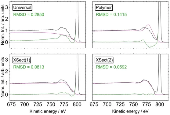
Figure 2 shows a fraction of the PTFE-Ref survey spectrum together with the QUASES fits based on four different cross sections. As explained above, the analysis of the CSNPs is based on the inelas-tic background related to the F1s photoelectron peak. Therefore, the optimization of the cross section is performed by fitting a 120-eV
kinetic energy range on the low kinetic energy side of this peak. The RMSD was always calculated as a criterion for the fit quality. For details on its calculation, see Section 3 of the Supporting Information. The universal and polymer cross sections are standard options pro-vided by QUASES. The QUASES fit is clearly improved by using the polymer instead of the universal cross section; however, the descrip-tion of the near peak region is still rather poor. The XSect(1) and XSect(2) cross sections have been optimized with respect to the experimental PTFE-Ref survey spectrum. Especially in the near peak region, both show superior agreement of spectrum and QUASES fit compared with the universal and polymer cross sections. While the XSect(1) cross section is based on the optimization of three parame-ters, the XSect(2) cross section, which clearly gives the best fit, involves an additional parameter which takes into account the band gap of the material. A mathematical description of all cross sections can be found in Section 4 of the Supporting Information.
2.3 | Confirmation of nonuniformity of the shell
thickness within a CSNP sample
All survey spectra of the investigated CSNPs as well as the uncoated PTFE nanoparticle cores can be found in Section 2 of the Supporting Information. The QUASES analysis of the survey spectra was always applied to the 120-eV kinetic energy range below the F1s
F I G U R E 2 QUASES analysis of the sample poly(tetrafluoroethylene) (PTFE)-Ref (bare PTFE cores) in order to identify the most suitable inelastic electron scattering cross section for the analysis of the polymer core-shell nanoparticle samples. Fractions from survey spectrum covering a 120-eV kinetic energy range below the F1s photoelectron peak. The experimental spectrum is depicted in black after smoothing and subtraction of the inelastic background caused by photoelectron signals at higher kinetic energies, the QUASES fits are depicted in purple, and the spectra after subtraction of the QUASES fit are depicted in green. The root-mean-square deviation (RMSD) values characterize the agreement between experimental spectrum and QUASES fit (for details on its calculation, see Section 3 of the Supporting Information). Each inelastic electron scattering cross section is defined by a formula in Section 4 of the Supporting Information
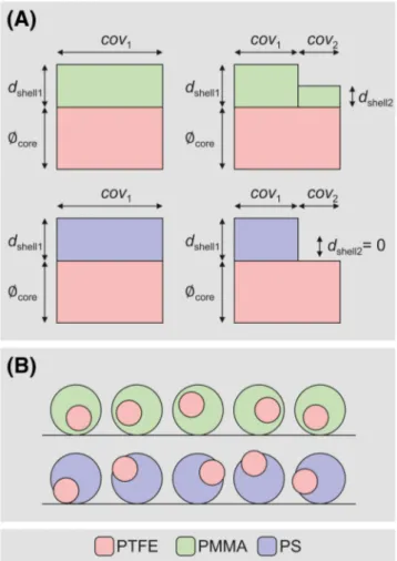
photoelectron peak. The minimum RMSD between spectrum and QUASES fit in this region was used as a criterion to determine the depth distribution of fluorine atoms. The nanoparticle shell thickness was determined as the topmost depth location of fluorine atoms in the nanoparticle. Furthermore, the“Islands (Active Substrate)”6 analy-sis option provided by the QUASES software package (see Figure 3A) was selected.
In order to confirm whether the shell thickness of the different CSNP samples is uniform or not, a “single island” model was first applied (see left part of Figure 3A) representing a single nanoparticle shell of thickness dshell1covering 100% (cov1= 1) of the cores in the
nanoparticle ensemble, that is, a complete encapsulation of the cores by the shell material. The fits with a minimum RMSD to the spectra of all five CSNP samples using the single island model are presented on the left side in Figure 4. The agreement between fits and experimental spectra is very poor, which indicates that all nanoparticle samples exhibit a nonuniform shell thickness. On the right-hand side of Figure 4, an analysis is done with a“two islands” model (see right part
of Figure 3A) representing two different shell thicknesses dshell1and
dshell2covering different relative fractions (cov1and cov2) of the cores
in the investigated nanoparticle ensemble. These QUASES fits are in almost perfect agreement with the experimental spectra. This demon-strates that the QUASES analysis can clearly identify the non-uniformity of the shell thickness in the CSNP samples without information from complementary techniques.
2.4 | Nanoparticle shell thicknesses from XPS
inelastic background analysis
Table 1 contains the shell thicknesses and relative coverages resulting from the QUASES analyses of the CSNPs, based on the two islands model in combination with either the XSect(1)- or the XSect(2)-optimized cross sections. Both results are included, in order to illustrate that an accurate cross section is essential to obtain the most detailed and accurate information on the CSNP internal structure. The most significant difference between the two cross sections is that dshell1is 0.5 nm for XSect(1) and 0.0 nm for
XSect(2). Since XSect(2) is most accurate (see Figure 2), it is con-cluded that dshell1 = 0.0 nm, which implies an incomplete
encapsulation of the core by the shell material. This conclusion is in agreement with the complementary analysis in Müller et al,8
which showed that all PTFE-PS CSNP samples deviate from ideality as depicted in Figure 3B. The incomplete encapsulation of the core by the shell material in the case of the PTFE-PS samples was also confirmed by Cant et al.15In this work, the uncoated area fraction
of the core for sample PTFE-PS(3) was determined from SEM micrographs to be 12%. This is in excellent agreement with the value cov1 of 15% calculated by the presented QUASES analysis.
The results in Table 1 for the PTFE-PMMA samples show that the shell thickness of these samples is also nonuniform; however, in contrast to the PTFE-PS samples, the encapsulation of the cores by the shell material is complete. This is also in agreement with the nanoparticle internal structure that was determined for these samples in Müller et al8 and is illustrated in Figure 3B. Uncer-tainties in the shell thicknesses determined from the QUASES analysis can be found in Section 5 of the Supporting Information.
The applied XPS experimental setup exhibits an analysis area of 300× 700 μm2. Therefore, a large nanoparticle ensemble of the mea-sured sample is investigated even though the CSNPs are prepared in a submonolayer. Consequently, the quantitative numbers obtained dur-ing the QUASES analysis represent this entire ensemble instead of individual nanoparticles. Further note that the nanoparticles vary not only in orientation (as shown in Figure 3(b)) but also in their degree of deviation from ideality. The shell thicknesses dshell1 and dshell2
weighted according to cov1and cov2obtained by application of the
two islands model in QUASES best represent the distribution of all shell thicknesses in the investigated CSNP ensemble, but a straight-forward interpretation of the dshelland cov results in terms of, for
example, the exact displacement of the core relative to the nanoparti-cle center is not possible. However, dshelland cov can provide relative
F I G U R E 3 (A) The“Islands (Active Substrate)” analysis option provided by QUASES in combination with either the“single island” or the“two islands” model. (B) Schematic representation of internal structure of the investigated polymer core-shell nanoparticles. This representation is idealized and does neither consider the
polydispersity nor the nonsphericity of the poly(tetrafluoroethylene) (PTFE) cores
estimates about the width of the shell thickness distribution of differ-ent samples to allow for a quick and straightforward comparison between several batches of a specific CSNP, different coating approaches, and so forth.
For the XSect(2) cross section, results from the single island model are also shown in Table 1, as well as the shell thicknesses deter-mined by T-SEM from Müller et al.8Both the QUASES analysis with
the single island model as well as the T-SEM analysis based on the dif-ference between average core and CSNP radius are expected to yield wrong shell thicknesses. Both analyses assume a single average shell thickness covering 100% of the cores in the nanoparticle ensemble, and this model is clearly wrong (see left part of Figure 4). It should be
noted that due to the lack of material contrast between core and shell material for these specific CSNPs, T-SEM micrographs cannot provide information about the uniformity of the shell thickness while the QUASES analysis in Figure 4 clearly demonstrates that this model is wrong. In Müller et al,8shell thicknesses were determined based on
an analysis of XPS elastic peak intensities using the SESSA software,2 and these values are similar to the thicknesses found here by the single island QUASES analysis. In a previous study,15 Cant et al also determined a single PMMA overlayer thickness for the sample PTFE-PMMA(1) by empirically fitting the XPS inelastic background and obtained dshell= 4.8 nm which is also close to the 5.5 nm found
by the presented single-island QUASES analysis. F I G U R E 4 Comparison of X-ray
photoelectron spectroscopy inelastic background analysis of the five different CSNP samples using the“Islands (Active Substrate)” analysis option provided by QUASES either in combination with the“single island” (left) or the “two islands” (right) model. Fractions from survey spectra covering a 120-eV kinetic energy range below the F1s photoelectron peak. The experimental spectra are depicted in black after smoothing and subtraction of the inelastic background caused by
photoelectron signals at higher kinetic energies, the QUASES fits are depicted in purple, and the spectra after subtraction of the QUASES fit are depicted in green. The root-mean-square deviation (RMSD) values characterize the agreement between experimental spectrum and QUASES fit (for details on its calculation see Section 3 of the Supporting Information)
It is expected that the shell thicknesses from T-SEM and the QUASES analysis with the single island model are both located between the two shell thicknesses from the QUASES analysis with the two islands model. This is true for all shell thicknesses from QUASES; however, the results from T-SEM of the samples PTFE-PMMA(2) and PTFE-PS(3) are clearly larger than all QUASES results. This is due to the combination of heterogeneity of the shell thickness and limited information depth of QUASES-XPS, which is approxi-mately 8× IMFP.13Basically, as long as the maximum shell thickness within the particles does not exceed the information depth, the cores of all nanoparticles are correctly detected independent of their orien-tation toward the detector. However, when the maximum shell thick-ness exceeds the information depth, some cores are no longer detected depending on the orientation of the nanoparticles toward the detector (see Figure 3B). This leads to an underestimation of the XPS results in comparison to T-SEM data.
3 | C O N C L U S I O N
In conclusion, it was shown that analysis of the inelastic background signal in XPS spectra of CSNPs can identify deviations from an ideal core-shell structure, including the nonuniformity of the shell thickness within a nanoparticle ensemble and the incomplete encapsulation of the cores by the shell material. Information from complementary tech-niques is not required. At the same time, nanoparticle shell thick-nesses dshelland relative coverages cov can be estimated, provided
that the nanoparticle shell thickness does not exceed the information depth of the method. The dshelland cov results can provide relative
estimates about the width of the shell thickness distribution of differ-ent samples to allow for a quick and straightforward comparison between several batches of a specific CSNP, different coating approaches, and so forth. To obtain this information, it is necessary to prepare samples with a submonolayer distribution of nanoparticles on the substrate and to use an optimized inelastic electron scattering cross section. This cross section can be determined by analysis of an experimental XPS spectrum of a pure reference sample consisting of the nanoparticle core material.
4 | A S S O C I A T E D C O N T E N T
Experimental methods, XPS survey spectra of CSNPs, root-mean-square deviation (RMSD) calculation, inelastic electron scattering cross section, and measurement uncertainties of CSNP shell thick-nesses from QUASES.
A C K N O W L E D G M E N T
This project has received funding from the European Metrology Pro-gramme for Innovation and Research (EMPIR) as part of the InNanoPart 14IND12 project as well as the ESCoShell 17SIP03
project. The EMPIR program is cofinanced by the European Union's Horizon 2020 research and innovation program and the EMPIR Partic-ipating States. The authors thank Dr Alexander G. Shard and Dr David J. H. Cant from the National Physical Laboratory (NPL) for helpful dis-cussions. Furthermore, the authors would like to express their grati-tude to Mrs Sigrid Benemann and Dr Vasile-Dan Hodoroaba from Bundesanstalt für Materialforschung und -Prüfung (BAM) for record-ing the SEM micrographs. Open access fundrecord-ing enabled and organized by Projekt DEAL.
O R C I D
Anja Müller https://orcid.org/0000-0003-2085-3687
Katia Sparnacci https://orcid.org/0000-0003-2102-9649
Wolfgang E.S. Unger https://orcid.org/0000-0002-7670-4042
Sven Tougaard https://orcid.org/0000-0003-0909-8764
R E F E R E N C E S
1. Mohai M. XPS MultiQuant: multimodel XPS quantification software. Surf Interface Anal. 2004;36(8):828-832.
2. Smekal W, Werner WSM, Powell CJ. Simulation of electron spectra for surface analysis (SESSA): a novel software tool for quantitative Auger-electron spectroscopy and X-ray photoelectron spectroscopy. Surf Interface Anal. 2005;37(11):1059-1067.
3. Shard AG. A straightforward method for interpreting XPS data from core–shell nanoparticles. J Phys Chem C. 2012;116(31):16806-16813. 4. Cant DJ, Wang YC, Castner DG, Shard AG. A technique for calcula-tion of shell thicknesses for core-shell-shell nanoparticles from XPS data. Surf Interface Anal. 2016;48(5):274-282.
5. Kalbe H, Rades S, Unger WES. Determining shell thicknesses in sta-bilised CdSe@ZnS core-shell nanoparticles by quantitative XPS analy-sis using an infinitesimal columns model. J Electron Spectrosc Relat Phenom. 2016;212:34-43.
6. Tougaard S. Software package to characterize surface nano-structures by analysis of electron spectra. 2020; see http://www. quases.com/. Accessed July 24, 2020.
7. Wang Y-C, Engelhard MH, Baer DR, Castner DG. Quantifying the impact of nanoparticle coatings and nonuniformities on XPS analysis: gold/silver core–shell nanoparticles. Anal Chem. 2016;88(7):3917-3925. 8. Müller A, Heinrich T, Tougaard S, et al. Determining the thickness and completeness of the shell of polymer core-shell nanoparticles by X-ray photoelectron spectroscopy, secondary ion mass spectrometry, and transmission scanning electron microscopy. J Phys Chem C. 2019; 123(49):29765-29775.
9. Tougaard S. Surface nanostructure determination by x-ray photoemis-sion spectroscopy peak shape analysis. J. Vac. Sci. Technol., A. 1996; 14:1415-1423.
10. Powell CJ, Tougaard S, Werner WS, Smekal W. Sample-morphology effects on x-ray photoelectron peak intensities. J. Vac. Sci. Technol., A. 2013;31(2):021402.
11. Powell CJ, Chudzicki M, Werner WS, Smekal W. Sample-morphology effects on x-ray photoelectron peak intensities. III. Simulated spectra of model core-shell nanoparticles. J. Vac. Sci. Technol., A. 2015;33(5): 05E113.
12. Tougaard S. Improved XPS analysis by visual inspection of the survey spectrum. Surf Interface Anal. 2018;50(6):657-666.
13. Tougaard S. Accuracy of the non-destructive surface nanostructure quantification technique based on analysis of the XPS or AES peak shape. Surf Interface Anal. 1998;26(4):249-269.
14. Sparnacci K, Antonioli D, Deregibus S, et al. PTFE-based core-shell nanospheres and soft matrix nanocomposites. Macromolecules. 2009; 42(10):3518-3524.
15. Cant DJH, Minelli C, Sparnacci K, et al. Surface-energy control and characterization of nanoparticle coatings. J Phys Chem C. 2020;124 (20):11200-11211.
16. Müller A, Swaraj S, Sparnacci K, Unger WES. Shell thickness determination for PTFE-PS core-shell nanoparticles using scanning transmission X-ray microscopy (STXM). Surf Interface Anal. 2018;50 (11):1077-1082.
17. Werner WSM, Chudzicki M, Smekal W, Powell CJ. Interpretation of nanoparticle X-ray photoelectron intensities. Appl Phys Lett. 2014; 104(24):243106.
18. Chudzicki M, Werner WS, Shard AG, Wang YC, Castner DG, Powell CJ. Evaluating the internal structure of core-shell nanoparticles using X-ray photoelectron intensities and simulated spectra. J Phys Chem C. 2015;119(31):17687-17696.
19. Baer DR, Cant DJH, Castner DG, Ceccone G, Engelhard MH, Karakoti AS, Müller A, Preparation of nanoparticles for surface analy-sis. In Characterization of Nanoparticles: Measurement Processes for Nanoparticles, 1st ed.; Hodoroaba, V.-D.; Unger, W. E. S.; Shard, A. G., Eds. Elsevier: 2019;295–347.
20. Tougaard S. QUASES-IMFP-TPP2M. 2019; see http://www.quases. com/. Accessed July 24, 2020.
21. Tanuma S, Powell CJ, Penn DR. Calculations of electron inelastic mean free paths. Surf Interface Anal. 1994;21(3):165-176.
22. ISO 18115-1. Surface chemical analysis–Vocabulary–Part 1: general terms and terms used in spectroscopy. 2013. (https://www.iso.org/ standard/63783.html).
23. Risterucci P, Renault O, Zborowski C, et al. Effective inelastic scatter-ing cross-sections for background analysis in HAXPES of deeply bur-ied layers. Appl Surf Sci. 2017;402:78-85.
24. Zborowski C, Tougaard S. Theoretical study toward rationalizing inelastic background analysis of buried layers in XPS and HAXPES. Surf Interface Anal. 2019;51(8):857-873.
S U P P O R T I N G I N F O R M A T I O N
Additional supporting information may be found online in the Supporting Information section at the end of this article.
How to cite this article: Müller A, Sparnacci K, Unger WES, Tougaard S. Determining nonuniformities of core-shell nanoparticle coatings by analysis of the inelastic background of X-ray photoelectron spectroscopy survey spectra. Surf Interface Anal. 2020;52:770–777.https://doi.org/10.1002/sia. 6865