Acknowledgements
I would like to thank to my PhD Supervisor Professor Salvatore Marano and my correlator Eng. Floriano De Rango, for support-ing me dursupport-ing these past three years and for their scientific advice and knowledge and many insightful discussions and suggestions. During studies I worked a lot with the nice people of the Culture Telelab (UNICAL), Dr. A.F. Santamaria, Dr. Peppino Fazio and other guys. I wish to thank all them for giving me an help for the research activity; their feedback and corrections have both helped me to improve my research world. It has been an enriching experience. I cannot forget the wonderful people from the Grupo de Redes de Computadores (GRC) of the Universitat Politecnica de Valencia, where I spent 4 fantastic months. Thanks to Dr. Pietro Manzoni and Dr. Carlos Tavares Calafate, for their advice, and giving me some ideas that were important for the last part of my Thesis work.
I would like also to thank Fabiana. She was always ready with con-stant encouragements for me and believing that this prestigious edu-cational qualification was achievable for me.
A special thanks to my family(mum, dad, Gilda and Ale). Words cannot express how grateful I am to my mother, and father for all of the sacrifices that you have made on my behalf. I would also like to thank all of my friends who supported me in writing, and incented me to strive towards my goal.
Thanks for all...
November 2015, Cesare Sottile
Abstract
0.1
ENGLISH
In this thesis, the design of efficient techniques for routing protocol suitable to Vehicular Ad-hoc NETworks (VANETs) has been pro-posed. In particular, the aims of the proposed protocols are to reduce interference issues, due to the data transmissions in wireless environ-ment. The proposed protocols use time series prediction models and also multi-objective metric, based on the evaluation of co-channel in-terference levels, end-to-end delay, and link duration probability along the different links from sources towards destinations. These param-eters are modelled through an optimization problem. The key fac-tors are to exploit the advantages available to the Standard 802.11p, based on a dynamic allocation mechanism of the DSRC spectrum, aimed at the reduction of the co-channel interference and the maxi-mization of the link duration probability (two key issues in vehicular environments). Another topic discussed in this thesis is related to the smart vehicular traffic management through VANETs infrastructure and communications(V2I and V2V). A distributed algorithm with the aim to build less congested path for the vehicles in a urban scenario has been developed. It is also considered the problem regarding to enhance air quality around the cities reducing the vehicles CO2 emis-sions. There are different causes related to the CO2 emissions such as the average travelled time spent by vehicles inside the city and their average speed. Hence, with a better traffic management the average time spent by the vehicles in the city will be considerably reduced as
well as CO2 emissions. These results are demonstrated in a discrete event simulator by using also real traffic data.
0.2
ITALIANO
In questa tesi sono stati effettuati degli studi per la progettazione di tecniche efficienti di routing adatte ai protocolli dinamici per le reti ad-hoc veicolari (VANETs). In particolare, i protocolli di routing proposti, hanno come obiettivo quello di ridurre il problema delle in-terferenze, che si vengono a creare durante la trasmissione di dati da parte dei nodi che compongono la rete in un ambiente mobile, sfrut-tando i vantaggi che lo standard 802.11p mette a disposizione. Alcuni dei protocolli proposti fanno uso di modelli di previsione legati alle serie temporali ed anche metriche multi-obiettivo, basate sul calcolo dell’interferenza co-canale, ritardo end-to-end e la probabilit´a della durata del link che compongono i cammini. Queste tre grandezze considerate, sono modellate attraverso un problema di ottimizzazione. Un secondo settore di interesse trattato in questa Tesi, legato alle strategie innovative di gestione del traffico veicolare nel contesto delle Smart-Cities. Sfruttando le potenzialit dellinfrastruttura delle reti VANETs, stato ideato ed implementato un algoritmo distribuito per ottenere una gestione efficiente del traffico veicolare in ambente ur-bano. L’obiettivo principale dell’algoritmo `e quello di fornire passo-passo, ad ogni veicolo facente parte della simulazione, una rotta meno congestionata per arrivare a destinazione. Inoltre, `e stato dimostrato mediante lutilizzo di un simulatore ad eventi discreti, che utilizzando tale algoritmo si ottengono riduzioni in termini di emissioni di CO2,
tempi di permanenza in citt da parte dei veicoli e di conseguenza anche un risparmio in termini di carburante.
Contents
0.1 ENGLISH . . . iii 0.2 ITALIANO . . . iv Contents v List of Figures vi Nomenclature vi 1 Introduction 1 2 Information and Communication Technologies to support the Smart Cities 5 2.1 Definitions of Smart City . . . 52.2 The initiatives of the European Union . . . 8
2.2.1 HORIZON 2020 . . . 9
2.3 The Italian Smart Cities . . . 10
2.4 Ministry of Education, University and Research (MIUR) and Ital-ian Player . . . 12
2.5 ICT applications for Smart Cities . . . 14
2.5.1 ICT applications in the Energy field . . . 14
2.5.2 ICT applications in the Environment field . . . 16
2.5.3 ICT applications in the Mobility and Transport field . . . 17
2.5.4 ICT applications in the Living field . . . 19
3 Reference Standards for the Vehicular Ad-hoc NETworks 21 3.1 Introduction . . . 21
CONTENTS
3.2 Physical parameters of the different reference standards . . . 23
3.2.1 DSRC/WAVE Standards . . . 25
3.2.2 The WAVE Physical Layer (PHY) . . . 26
3.2.3 WAVE Medium Access Control . . . 28
3.2.4 The WAVE WSMP . . . 30
3.3 Continuous Air-interface, Long and Medium Range (CALM) . . . 31
3.4 Cooperative Awareness Messages (CAM) Protocol . . . 35
3.4.1 Timing Requirements . . . 36
3.4.2 Interfaces . . . 37
4 A Predictive Cross-layered Interference Management in a Mul-tichannel MAC with Reactive Routing in VANET 39 4.1 Interference Management in a Cross-Layered View . . . 40
4.1.1 Proposal summary . . . 40
4.1.2 Problem Statement in Interference Management at routing layer . . . 41
4.1.3 SIR evaluation on multi-channel MAC . . . 46
4.1.4 Dynamic Channel Switching Procedure . . . 47
4.1.5 Predictive Interference Metric . . . 48
4.1.6 Smoothed metric . . . 52
4.1.7 Interference aware On Demand Routing Scheme . . . 52
4.2 Performance Evaluation . . . 53
4.2.1 How to choose protocol parameters in PIAR protocol . . . 54
4.2.2 Protocols performance evaluation . . . 57
5 Routing Optimization in Vehicular Networks: A New Approach Based on Multiobjective Metrics and Minimum Spanning Tree 63 5.1 State of the Art and Related Work . . . 64
5.1.1 QoS Routing Protocols . . . 64
5.1.2 Location-Based Routing Protocols . . . 64
5.1.3 MAC Layer Protocols . . . 66
5.1.4 Multiobjective Routing Protocols . . . 66
CONTENTS
5.1.6 Other Protocols . . . 68
5.2 Problem Statement, Contribution, and Proposed Protocol Scheme 68 5.2.1 Scenario Description . . . 69
5.2.2 The Main Terms of the MO-RP . . . 70
5.2.3 Linear Optimization Problem . . . 72
5.2.3.1 Constraints Definition . . . 74
5.2.3.2 What about Mobility . . . 76
5.2.3.3 Minimum Spanning Tree (MST) . . . 76
5.3 Performance Evaluation . . . 78
6 Safety enhancement and CO2 reduction in VANETs 86 6.1 Architecture . . . 87
6.1.1 System . . . 87
6.1.1.1 On Board Unit (OBU) . . . 87
6.1.1.2 Road Side Unit (RSU) . . . 88
6.1.1.3 City Traffic Monitoring Device (CTMD) . . . 89
6.1.1.4 City Traffic Manager (CTM) . . . 89
6.1.2 On Board Device Cooperation . . . 90
6.2 Protocol proposal based on IEEE802.11p standard . . . 91
6.2.1 Position Update . . . 92
6.2.2 Warning Message . . . 92
6.2.3 Collision avoiding messages . . . 93
6.2.3.1 Collision Start Message . . . 94
6.2.3.2 Collision End Message . . . 95
6.2.4 Topology Update . . . 95 6.2.5 CTM related messages . . . 96 6.2.5.1 Congestion Check . . . 96 6.2.5.2 Congestion Ack . . . 97 6.2.5.3 Congestion Update . . . 97 6.3 Problem Description . . . 98
6.3.1 Road and Lane definitions . . . 98
6.3.2 Neighbours discovery . . . 99
CONTENTS
6.3.3.1 Graph and networking . . . 100
6.3.3.2 Metrics definition . . . 101 6.3.3.3 Routing Algorithm . . . 102 6.3.4 Congestion management . . . 102 6.3.4.1 Departure model . . . 106 6.3.4.2 Cost computation . . . 107 6.4 Simulation Results . . . 107 6.4.1 Network Simulator . . . 108
6.4.1.1 Neighbour Threshold evaluation . . . 110
6.4.1.2 Protocol Overhead . . . 111
6.4.1.3 Effects on Air Pollution . . . 112
6.4.1.4 City traffic block and congestion management . . 113
6.5 Advanced Simulations using Real Traffic Data of the Bologna’s City116 6.5.1 Enviromental Setting of the Considered Scenario . . . 116
6.5.1.1 Traffic Information . . . 117
6.5.2 CO2 Emissions Evaluation . . . 119
6.5.3 Monitoring the Number of Congested Roads . . . 119
6.5.4 Total Average Time spent in the City by the Vehicles . . . 120
6.5.5 The Trend of the Cumulative Vehicles’ Number on a con-gested road . . . 121
7 Conclusions, Publications and Future Work 123 7.1 Publications . . . 124 7.1.1 Journals . . . 124 7.1.2 Book Chapters . . . 125 7.1.3 International Conference . . . 125 7.1.4 Future Work . . . 127 Bibliography 128
List of Figures
2.1 An example of Smart City . . . 7
2.2 Services that can be made in a Smart City . . . 9
2.3 Smart City Services to monitor the energy consumptions . . . 14
2.4 Network Infrastructure for the Smart City . . . 16
2.5 An example of ITS service . . . 18
3.1 The DSRC Frequency Allocation in United States . . . 24
3.2 The WAVE Protocol Stack and Its Associated Standards . . . 25
3.3 The TDMA Extension of WAVE MAC . . . 29
3.4 The TDMA Extension of WAVE Medium Access Control . . . 30
3.5 CALM Standard logo . . . 31
3.6 Example of a two part solution for in-vehicle implementation of CALM . . . 33
3.7 CALM General Architecture . . . 34
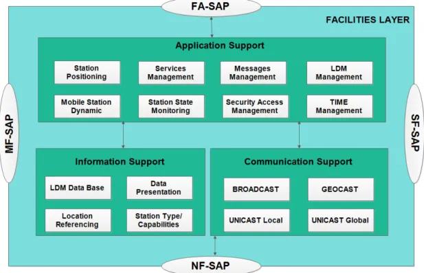
3.8 Facilities Layer Architecture . . . 36
3.9 Time requirements for CAM generation and CAM processing . . . 37
4.1 Multi-channel EDCA extension for WAVE specifications. . . 41
4.2 Path Discovery (PD) procedure in IAR protocol and SIR compu-tation. . . 45
4.3 PD (Path Discovery) procedure in IAR protocol. . . 46
4.4 Signaling packets in IAR Protocol . . . 48
4.5 Threshold-based dynamic channel refresh procedure. . . 49
4.6 Predicted SIR values with N=25 and M=10. . . 51
LIST OF FIGURES
4.8 Packet Delivery Ratio for different values of N and M. . . 55
4.9 System throughput vs Probes-timer Tp. . . 56
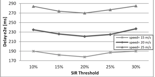
4.10 Delay end-2-end versus threshold D. . . 56
4.11 Network Packet Delivery Ratio for 20 active connections. . . 57
4.12 Network Throughput with 20 active connections. . . 58
4.13 Network overhead with 20 active connections. . . 59
4.14 Average Normalized SIR value for 20 active connections. . . 60
4.15 End-2-end delay for 20 active connections and 60 mobile nodes. . 61
4.16 Network Packet Delivery Ratio versus speed of nodes. . . 62
5.1 An example of a VANET scenario. . . 70
5.2 Flow chart of neighbor discovery process. . . 72
5.3 An example of a generic link and its related weights between two generic nodes (x, y). . . 73
5.4 Delay, SIR, and LDP average values versus available solutions. . . 80
5.5 Feasibility of the found solutions. . . 81
5.6 PDR trend for different values of αi. . . 81
5.7 Average throughput trend for different values of αi. . . 82
5.8 Average PDR versus the number of mobile nodes. . . 83
5.9 Average aggregated throughput versus the number of mobile nodes. 84 5.10 System overhead for 40 mobile nodes. . . 84
5.11 The average e2e for the proposed protocol. . . 85
6.1 Reference Layered Architecture . . . 88
6.2 RSU - High Level Block Diagram for the core thread of the RSU . 89 6.3 Wave Short Message (WSM) - Packet format . . . 91
6.4 Position Update inner function flow chart . . . 93
6.5 Car Accident Messages Diagram Timing . . . 94
6.6 Road Congestion Identification process . . . 96
6.7 CongestionAck(congAck) message format . . . 97
6.8 Neighbours Discovery using different NT H, as is shown changing this value it is possible to consider a wider or a narrower space. . 99
6.9 Links’ weight definition . . . 101
LIST OF FIGURES
6.11 Neighbour Threshold impact on the flooding of the signalling mes-sages . . . 109
6.12 Neighbour Threshold relationship with the number of collisions . . 110
6.13 Average Signalling Packet . . . 111
6.14 Average Carbon Dioxide (CO2) Emission per vehicle . . . 112
6.15 Safety Enhancement for WAVE based protocol (SeAWave) Average Number of Accidents vs. Driver Distraction Coefficient (DDC) increasing. . . 113
6.16 SeAWave congestion avoidance behaviors . . . 114
6.17 Average speed of the vehicles vs. the ingoing rate increasing, the ingoing rate is given by the sum of each ingoing rate measured at the gates of the city block which has been considered, (see Fig.6.10)115
6.18 Average Time Spent in the City per vehicle vs. increasing of vehicle input rate at the input gates . . . 115
6.19 The Map of Bologna’s City . . . 117
6.20 Overhead and redundant reduction . . . 118
6.21 The comparison between real traffic scenario and the Seawave pro-tocol in term of CO2 Emissions . . . 119
6.22 The comparison of the number of congested roads between the real traffic scenario and the SeaWave Protocol . . . 120
6.23 The comparison of the avg time spent of the vehicles in the city between the real traffic scenario and the SeaWave Protocol . . . . 121
6.24 The Cumulative Vehicles Number trend for the real traffic scenario and the SeaWave Protocol . . . 122
Chapter 1
Introduction
A city can be defined Smart when there are investments in human and social capital and traditional (transport) and modern (ICT) communication infrastruc-tures fuel sustainable economic growth and a high quality of life, with a wise management of natural resources through participatory governance.
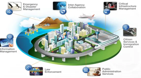
A smart city may be seen as a complex infrastructure of system of systems. The use of information and communication technology to sense, analyse and integrate the key information of core systems in running cities. At the same time, smart city can make intelligent response to different kinds of needs (e.g. daily livelihood, environmental protection, public safety and city services, industrial and commercial activities).
Nowadays one of the hottest theme is the application of the newest tech-nologies in road safety. Several proposals have been made and both US and European standardization institutes are working on them. Drivers are respon-sible of several accidents on the roads, therefore, applications based on the de-tection of dangerous behaviours are one of the many reasons why Vehicular Ad-Hoc Network (VANET) technology and its related standard have spread. In these last few years car manufactures and Governance Institutions invested in IEEE802.11p standard (for US) and ETSI ITS (for Europe) to increase active and passive safety systems. The European standardization process produced the Cooperative Awareness Message (CAM) format to continuously disseminate sta-tus information about a vehicle. CAM message is sent in a broadcast way to all nearby vehicles when a set of rules is met. Broadcasting of Safety Message
(BSM) approach introduced in USA, aims to calculate waiting time of each node based on local density and distance trying to reduce the number of unnecesary broadcasting message in Vanet environment. This algorithm is fully distributed, and it needs only local information collected by the nodes.
In this thesis, will be addressed issues regarding the efficiency of routing pro-tocols suitable for networks that have strong mobility problems and algorithms design for the efficient management of vehicular traffic, exploiting the distributed wireless networks. Vehicular networks can provide support for ITS applications (Intelligent Transportation System), oriented to road safety and information ser-vices and entertainment. The main advantage is the absence of an infrastructure, typical of centralized networks, that makes them very scalable and adequate for highly-variable network topologies. On the other hand, communication protocols become very complex and, sometimes, signaling overhead may waste bandwidth availability.
Vehicular communication systems represent one of the most desirable tech-nologies when the safety, efficiency, and comfort of everyday road travel need to be improved. VANETs provide wireless communication among vehicles and among vehicle and road-side units (RSU) equipments. Communication perfor-mance and Quality of Service (QoS) strongly depend on how the routing takes place in the network, on how protocol overhead affects the available bandwidth, and on how different channels are selected in order to minimize interference levels. When evaluating network topology through its routing table and, in the consid-ered case, the availability of different available channels, a protocol may enhance the quality of communication. So, in this scenario, each node should select the best route in terms of QoS, not only considering a typical cost metric (band-width, delay, traffic load, or a combination of them), as in the classical multihop architecture, but also taking into account the benefits that can be obtained if dif-ferent interference levels, that is difdif-ferent channels, are considered. QoS routing in multi-hop wireless networks is very challenging due to interferences among dif-ferent transmissions, but VANETs offer the chance to reduce them since multiple simultaneous transmissions are possible.
In detail, a new routing protocol for interference reduction and link-duration enhancement is proposed for VANET environments, taking the advantage of a
dynamic allocation of the Dedicated Short Range Communications (DSRC) spec-trum, in order to reduce interference level among mobile nodes and to increase the overall link stability in the considered network. The proposed scheme can be integrated with different already-implemented routing protocols and its met-ric takes into account the best values of co-channel interference, link duration probability and the term of end-to-end delay. Regarding the data dissemination in vehicular networks, our protocol does this purpose through the mechanism of construction of the Minimum Spanning Tree (MST), in order to diffuse the messages to a large number of vehicles. We decided to use the MST technique to minimize the number of transmissions so as reducing interference due to transmis-sions of neighbouring vehicles. Spanning trees are widely used in communication networks as a mean for dissemination information from one node to all other ones and/or to collect information at a single designated node. So, this protocol aims to choose different channels along the path from a source to a destination, obtaining a global metric minimization for the considered connection.
Considering that the protocol overhead is an important issue to be addressed because several kinds of messages have to be used to activate active and passive safety systems in vehicular environment. This increment is caused by messages flooding. Taking care about these considerations we have designed a VANET protocol paying attention on overhead issues as well, by spreading information towards on-board safety system notifying messages to the drivers exploiting the OBU. Another important aspect of the traffic management that we considered is to enhance air quality around our cities reducing vehicles’ CO2 emissions. There
are different causes related to the CO2 emissions such as the average travelled
time spent by vehicles inside the city and their average speed. Hence, with a better traffic management the average time spent by the vehicles in the city will be considerably reduced as well as CO2 emissions. In order to demonstrate these
results, we designed a full integration framework. The thesis is organized as follow:
• in the Chapter 2 are described how the ICTs and the telecommunication systems are employed in the modern concept of Smart City and their ap-plication,
• in the Chapetr 3 are illustrated the most important Standards developed for Vehicular Ad-hoc NETworks,
• in the Chapter 4 is described a novel routing protocol for Vanets, based on predictive channel selection to build robust paths, from source node to the destination node,
• in the Chapter 5 is presented a multi-objective routing protocol for vehicular network, in order to increase the QoS in mobility environment,
• in the Chapter 6 is presented a Smart Traffic Management Protocol called SeaWave, in order to improve traffic situation in urban simulated scenario and also by using real traffic data.
Chapter 2
Information and Communication
Technologies to support the
Smart Cities
2.1
Definitions of Smart City
In recent years, the concept of ”Smart City” is came out and may be linked to the world of the institutions (the European Union in the first place) and also to companies in the world of technological innovation and research centres of the most famous Universities of the world. This concept can also encompass different aspects of social life in our cities. In fact, in the literature there are some publications that focus more attention on the infrastructure ICT, other than studying the correlation between the accessibility of the ICT infrastructure and level of the development of a territory, and others that put more attention to the human and cultural capital and education. An early definition of Smart City that struck me is that of Hollands, which states that ”a smart city must be able to use the ICT infrastructure to improve economic efficiency, to promote political, cultural and urban social development.
From this statement it can guess that the ICT infrastructure is an enabler and central factor to a successful project of the Smart City, thus related to support and improve the liveability of the human and cultural capital of a territory. Do not
underestimate the economic aspect, because the Smart Cities are also born with the aim of increasing productivity and saving in consumption of raw materials both for the companies, the institutions and not least also for the citizens.
A further definition that we can consider, is related to the English city of Southampton, which sees in the Smart City, a chance to promote social inclusion in the utilities factor. Social inclusion is a goal pursued by both small towns than larger ones. In this context it is possible to find the plans of e-government systems and democratic participation of the city, seeing the participation of citizens in a way to empower them and make they part of city life. I consider important this last definition of the Smart City, because they were made several scientific pub-lications, considering aspects related to the environment and eco-sustainability. For sustainability understood in terms of environmental and energy resources, and sustainability viewed as maintaining a competitive advantage in time sufficient to ensure a decent or better life for future generations.
Beyond the possible definitions, the term Smart City is associated mainly with the Information and Communication Technologies (ICT). ICT is the key to the implementation of a Smart City as they represent a key factor to support services for the citizen. Therefore, the ICTs are seen as a means through which convey information and services. Obviously, the ICT alone are not enough. When designing a Smart City, we must consider other peculiar factors relating to each city: the human and cultural capital.
The term ”smart” is understood as the intelligent use of resources of a terri-tory, in almost cases are referred to energy. Very recently, major manufacturers and suppliers of energy services, are increasingly affecting the issue of energy sus-tainability. In this area work the ”Smart Grids”. They are born with the following purposes, today the city as well as being an energy consumer, will also become a producer (for example, by installing solar panels on their homes). Therefore, the Smart Grids have the task of managing efficiently and automated electrical system not only referring to the large centralized power plants, but distributed throughout the solar panels or wind turbines. Obviously, if we support what has been said now regarding the concept of sustainable energy, the goal of the Smart Cities will be to achieve self-sufficiency through the use of solutions with low environmental impact and low emission. Smart Cities are also proposed to solve
problems related to the mobility of citizens. In fact, they are intended to main-tain a careful management of the critical daily, with solutions that exploit the use of sensor networks and distributed wireless networks, which monitoring the state of the traffic in real-time, or the presence of accidents, in order to inform citizens and suggest them an alternative route, or invite their to postpone his commitments. Regarding the e-government, the idea on which the Smart Cities
Figure 2.1: An example of Smart City
are based is to give the opportunity to citizens to be able to manage relationships with the public administration via Internet connection staying at home or at any place and time.
Finally, another aspect that has been developing recently is called ”e-health”. It aims to computerize the typical tools of Health (prescriptions, medical records, etc.), but also to create a system which, through the use of patient data, allowing to program properly the activities of hospitals or private health care; for example, having the ability to isolate any risk factors for the health of citizens.
2.2
The initiatives of the European Union
The topic of Smart Cities is treated by the European Union in a very strong and innovative manner, focusing on the potential of new initiatives to integrate differ-ent intervdiffer-entions and addressing and solving everyday the problems of the city. The concept of Smart cities ranks first in the Annual Programme of Work of 2012, drawn up by the European Commission; it focuses on the theme of cooperation between countries and EU Member States and is part of the Seventh Framework Programme for Research and Technological Development (2007-2013). The pro-gram has made available a budget of 50 billion of Euros, focusing on the great potential existing in the field of research and innovation. They are defined as key factors for competitiveness, employment, sustainable growth and social progress. As for the Seventh Framework Programme (FP7), it is divided into ten themes and the initiative of the Smart Cities is located on the fifth theme, that regarding on energy policies. The need to adapt energy systems more sustainable, less de-pendent on imported oil and based on a set of renewable energy resources, is the main goal to lead the European challenge to a high security of energy supplies and to begin to work concretely on the problem of climate change, in order to increase also the competitiveness of the European market. With the definition of the Horizon 2020 program, the European Union draws a clear path to emerge stronger from the crisis, making all member states more competitive and able to adapt to the growing challenges of globalization. To achieve this, have been set targets to be achieved by 2020:
• 75% of people aged between 20 and 64 years old must have a job; • 3% of the EU’s GDP should be invested in research and development; • the goal of ”20/20/20” on the environment and energy (to reduce emissions
of greenhouse gases by at least 20% compared to the levels of the year 1990; 20% of final energy consumption from renewable energy and 20% improvement in energy efficiency);
• the drop out rate by students of secondary schools must be under 10% and at least 40% of the younger generation should have a tertiary degree;
Figure 2.2: Services that can be made in a Smart City
• to reduce by 20 million the number of people to be risk of poverty.
2.2.1
HORIZON 2020
Horizon 2020 stems from the awareness that the resources allocated by states and private companies to research and innovation decreased dramatically. Guilty before all the current crisis. Thus, Horizon 2020 aims to reduce the risk linked to research, and then directly fund research proposals from the world of institutions and individuals, whether it is large multinationals or to small and medium enter-prises. To meet the needs of companies, in Horizon 2020 are provided mechanisms for simplify and speed up procedures for obtaining funding and a simplified ac-counting of expenses in order to ensure the recipient of financing the possibility of being able to focus on what really matters, that is research and innovation. Obviously a lot of attention is paid to the selection of the proposals with a careful ex-ante and an equally careful evaluation during and at the end of the project is made. The mechanism which is adopted in order to access funding from the community expects a response from interested parties to the ”call”. This is not generic call but issues related to the specific purpose, that the Europe 2020
Strat-egy want to pursue. Within Horizon 2020, and the FP7, there are already several calls regarding the Smart Cities, with a total budget of 449.5 million of Euros.
2.3
The Italian Smart Cities
Italy country had a different story compared to cases generally related to the cities in other European countries, about the phenomenon ”Smart Cities”. The main fault could be attributed both to the slowness in grasping the message of innovation that the general indifference. An indirect benefit that Italy could take is to assess weaknesses, problems and also the strengths of a strategy that changes according to the context of reference as these innovations require a fairly long period of running. The first major difference about other European cities is related to the concept of ”City”. In fact, pilot projects presented to the call of the European Smart cities and Communities for the italian city, refer to certain neighborhoods or areas, considered to be particularly interesting to accommodate advanced technology, to achieve the European objectives set out, among which we list: the reduction of CO2 emissions, the design and development of new
inte-grated systems, a new relationship between public and private entities and public awareness. The smart city concept begins to be formalized with the agreement between SMAU (International Exhibition of Information & Communication) and ANCI (National Association of Italian Municipalities); in which is established the ”Italian Observatory on Smart cities” and also with the introduction from the Ministry of Education (MIUR) [1] the line of research: ”Smart City as a strategy for the entire country”. The most important purpose of the observatory is founded with the agreement SMAU-ANCI. It is to sensitize the public administrations on the issue of Smart Cities, trying to make easy the collaboration with the private sector or companies. The Observatory’s goal is to understand how, through the use of the ICT, it can improve the quality of life in urban spaces, for example in terms of mobility, energy-saving policies, municipal waste management and citizen services. In the SMAU appointment, which took place in Milan on 20 October 2011, the participating administrations (the towns of Bologna, Genoa, Milan, Piacenza, Pisa, Prato, S. Giovanni in Persiceto, Venice and Turin), along with a few companies have signed a collaboration agreement to create observers
for Smart cities, introducing innovative technologies and new models of manage-ment of administrative machinery. All this was intended to encourage cities to be open track project European Smart cities, to realize substantial cost savings and ready to face the challenge toward more sustainable cities. The SMAU-ANCI as-sociation has in the main aim also to facilitate direct contact between supply and demand, to entice the private sector to invest in urban areas well defined [2]. A known consulting company called Net-Consulting [3], states that the Italian cities are nowadays forced to chase the new concept of Smart City to not fall behind those European thus starting, the economic recovery is absolutely necessary in or-der to improve economic conditions and social rights of citizens. Net-Consulting provides also a definition of Smart City as follows: ”A set of simple or complex solutions aimed on two objectives: the smart management of the services that is provided by the municipality and the implementation of critical projects in areas of the city as intelligent safety, traffic, youth marginalization, the economic attraction of a territory ”.
For medium and small cities Italian was presented a new contract in Horizon 2020 project [4], where they have already joined in 1800 common to the Covenant on the Smart City development strategy. The issues that usually are being car-ried out are: spatial planning and housing stock (considering recovery actions of existing assets), upgrading of the urban environment and to invest in technology services, intelligent services for urban mobility, such as detectors of info-mobility for the efficient management of traffic and devices for video surveillance; regarding the spread of renewable energies are defined different campaigns for photovoltaic plants, building a smart grid and manage efficient disposal and waste recycling.
A final macro-area is dedicated, to the modernization and simplification of the administrative machine, with projects such as ”e-government”, which aim to create a new interaction between the citizen and the companies[5].
2.4
Ministry of Education, University and
Re-search (MIUR) and Italian Player
The Italian government has developed a variety of programs and operational strategies, which address the development and the implementation of the Smart City concept. This strategy is considered a dual policy, as it points out, on the one hand, ”the will to face the problems of great social importance, such as the reduction of emissions through clean technologies, intelligent infrastructures for mobility, the realization of urban models and homes more sustainable, more ef-ficient health care, welfare fair and new technology for the ageing society and for people in conditions of difficulty”, and on the other hand, ”it is necessary to capitalize the efforts to improve the lives of citizens by increasing technological capacity, competitiveness and growth potential of the enterprises”[6]. A funda-mental role has also the simplification decree of the article n.49 on the Italian Digital Agenda of 27 January 2012, strongly desired by Prime Minister Mario Monti. This Simplification Decree introduces important concepts and essentials for the realization of the strategic project on Smart Italian city. The objectives of the Digital Agenda Italian are [6]:
• the introduction of support to the growth of smart communities, in order to increase participation and awareness of citizens within the administrative machinery;
• Open data projects, to make public the information assets of the public administration and promote better interoperability;
• improve services to citizens through e-government projects, for an open and transparent public administration;
• dissemination and development of cloud computing architectures, connected to the activities of public administration;
• to develop channels of e-commerce to promote the use of new technologies; to simplify the access to the Internet for all citizens with broadband in-frastructure or extra large in schools, universities, urban spaces and public places;
• finally, to develop e-learning projects for modernizing an educational system that is in step with the changes taking place in society.
In Italian territory, the most important companies of telecommunications, energy suppliers and Information Technology, have accepted the challenge of in-novation in accordance with the ministerial programs. Enel company will play an important role for the realization of innovative distribution network, to achieve energy saving but also to decrease the cost of energy to the citizens. Enel has been assigned the role of manager of the electricity infrastructure. In this sense, it plans to ensure that systems of direct self-production and distribution of energy level also for the condominiums; systems that can be solar roofs or mini power plants and even structures with systems capable of storing the local energy, leav-ing to the consumers, the decision of its policies of energy consumption. Enel decides how much energy deliver outside, taking part, as well, to the electricity market. Telecom Italy about two years ago launched an initiative, on the Smart cities, called ”Smart Town”. This initiative provides the opportunity to make sustainable, from an economic and environmental point of view, the adoption of new intelligent services. The aim of Telecom Italy is to create new services, without change the approach to service. The project involves the integration of communication networks through applications that allow to have direct in-formation on the users mobility, security and public lighting. Thus, it tends to improve the quality of the citizens’ life and to distribute services especially to public administrations, as operators of the platform city.
IBM Italy instead will focus on the production of data management systems with their software. IBM wants to create an integrated heterogeneous manage-ment of data, to govern the phenomena that occur in the territory. IBM designed an Intelligent Operations Centre, which has the task of integrating the data com-ing from the sources, and to interpret them.
CISCO Italy focuses, instead, on the spread of broadband. The company’s interest is to spread as much bandwidth as possible, having the necessary in-frastructure to develop different devices, for example to realize the teleworking, which reduces travel as it is working at the CUD of Amsterdam.
We could be analyse many other companies, but even from this brief descrip-tion, it is understood that the subject business-oriented needs to be managed by
a metropolitan breath strategy to avoid falling into the error to have exclusively a high technology Smart City.
2.5
ICT applications for Smart Cities
The following section describes the main applications related to the world of ICT in various areas ranging from the domain of energy, environmental, living, transport and mobility.
2.5.1
ICT applications in the Energy field
In the field of public lighting, it is possible to remotely control electric street lights through dedicated software (Remote Dimming and Control) that can adjust the light intensity depending on the conditions of a specific area, with energy savings up to 20%. It is also possible to take advantage of the widespread presence of street lights in the city to offer other services, such as free Wi-Fi or the monitoring of traffic, pollution and weather conditions, through the use of wide-area network (WAN). Among the best known examples, which include the Intelligent Lamp-post installed in Malaga or those of Santander, they can independently adjust its brightness according to the brightness of the environment and the natural flow of traffic. The Smart Grid along with computer networks allow two-way
commu-Figure 2.3: Smart City Services to monitor the energy consumptions
energy sources. They represent the paradigm of the future in the production and distribution urban energy. These will be able to improve the management and distribution of electricity, thanks to constant monitoring of electricity con-sumption and the transformation of the consumer into a ”pro-sumer” (producer / consumer). They will be able to sell the energy produced and actively participate in the energy market. This inevitably leads to reconsider the existing business models, focusing on the big players distributors of the service, so that they are also protected other players who have not longer a marginal role, thus achieving sustainable investments. Today, , there are still a series of barriers related to:
• standard, both in terms of semantics (data model) and syntax (protocol); • lack of technological maturity, including also that the electric vehicles to be
integrated;
• governance of the system;
• lack of expertise of the utilities of the ICT.
A key aspect behind the development of the Smart Grid is the presence of decentralized storage systems, which are essential for the network integration of the renewable energy sources.
Among the technologies enabling the Smart Grid there are: smart meters in the homes, the Advanced Metering Infrastructure (AMI), which allows to es-tablish a channel of communication between the control system and information system; the Demand Side Management, it is a smart software capable of cross-ing in real-time supply and demand. Finally, the Micro Grids are defined as the points within the city energetically balanced such as hospitals, university cam-puses or shopping centers, which are able to produce an amount of energy at least equal to its consumptions.
In the field of renewable energy, the scenario changes a lot depending on the specific technology treated. Among all, the photovoltaic appears that more competitive in Italy, thanks to different reasons:
• in the last five years there was a reduction of over 50% of the investment costs in the construction of photovoltaic systems;
• the geographical position of Italy that allows optimal level of radiation; • in recent years, there was an increase of the price of crude oil and therefore
the energy (common aspect to all sources of renewable energy).
2.5.2
ICT applications in the Environment field
Sensor networks are revealed in this domain an indispensable factor in the mon-itoring of water, waste and pollution, with clear advantages over the entire plan-ning cycle and the resulting productivity, thanks to a level of technological ma-turity already acquired. However, the spread remains low due to the high initial investment.
In water management, the Advanced Metering Infrastructures (AMIs) enable to promptly intervene on the possible failures or malfunctions in plumbing pumps. An interesting experience in this area is made in Gothenburg City. Where, for the first time in Europe, they are thinking to replicate for the water control, the positive experience had in the energy field with the installation of 90,000 smart meters based on ZigBee communication infrastructure[7]. The AMI could also be
Figure 2.4: Network Infrastructure for the Smart City
used in waste management, and particularly to monitor in real-time of the filling level of the bins; so as to optimize also the path of the waste collection vehicles, such as is already in the city of Santander.
In the cities where it is already spread the door-to-door collection, the Ra-dio Frequency Identification (RFID)technology can also used, to attach the low frequency tags on the waste bags the information of the provenance house. The ultimate goal would be to greater empowerment of the people on the subject, thanks to incentive mechanisms that go to reward good behaviour in terms of recycling.
The main limitations of this approach are given by:
• the need to have a system for collecting door-to-door, able to associate the waste to the user;
• difficulties to implement the projects proportionally to the population size of the city;
• inability to implement incentive mechanisms without a logic of payment service, based on tariff and non-tax type.
2.5.3
ICT applications in the Mobility and Transport field
In general, the transport in urban areas generates huge external costs attributable to:• greenhouse gas (human health, agriculture, climate change, water availabil-ity);
• air pollutants (human health, damage to buildings, land, water); • noise pollution (health, interventions on buildings, vibration);
• congestion (loss of time, health, inefficiency of the production system); • security (quality of life, health, accident).
The mobility issue, which takes a central role in the Smart City, comprises two main areas of technology, one related to the Intelligent Transport Systems (ITS) and the second one to the development of alternative energy sources to oil, with particular reference to the electric.
The Internet-of-Things (IoT) will change the cars in hub able to exchange information with the outside world, for example with the road infrastructure (Vehicle-to-Infrastructure Communication) or other vehicles (Vehicle-to-Vehicle Communication). This will also facilitate the control systems or paid access in urban centres. The adoption of interoperable electronic ticketing will reduce
Figure 2.5: An example of ITS service
the costs associated with the issuance of the travel documents, facilitating a logic of dynamic pricing user targeted; as already happens in Tallinn City for several years, and ensure a more accurate monitoring of actual demand, which is essential to improve the supply. Even the spread of the alternative mobility systems as bike-sharing, car-sharing or car-pooling, is linked to the possibility to take advantage in the fast and simple way, for example through a unique services card.
Finally, the applications of the driver support in the search and reservation of parking [8][9] will help to reduce congestion in the city centres. For exam-ple, Streetline Company provides solutions that, through the use of technology infrastructure (parking sensors, smart parking meters and database), assist the user to find a parking spaces. Both the municipal authority for parking is private dealers pay therefore the application to be displayed on the user’s query during the use of the service. Even traders are stakeholders of the system, because the parking produces positive externalities and they also could use the application, encouraging the customer to the purchase of its product through parking-pass.
It should also be underlined the presence of a double infrastructure level. The sensors and parking meters are in fact provided directly by the company, while mesh networks to connect them to be already present in the city, as well as an operator (e.g. a company of TLC) that manages it. The driver achieves greater individual productivity, while the city benefits from a reduction in traffic and CO2 emissions, thanks to dynamic pricing policies on public car parking, that line supply and demand. The same logic can be used also in city logistics for reservations the stopping places. In city-logistics on the one hand, it is trying to internalize the market price of the goods but the external costs now fall on the community, in the other to rationalize logistics flows. In addition, the Italian cities enjoy special features that make the theme of central importance of the Smart City, such as:
• dense city centres;
• historic centres to which access is difficult due to narrow roads; • high presence of shops in central areas;
• strong presence of transport on own account [10]; • protection of the artistic heritage.
2.5.4
ICT applications in the Living field
In the health sector, are spreading solutions for monitoring the patient’s health remotely. It is able to increase the level of service perceived by the user, while reducing the costs. In fact, there are devices that measure the vital signs of the user, and in case of anomalies in the data it will send through a domestic or a centralized hub to the nearest hospital, by using a simple smartphone.
The same technologies are also applicable to private care services to the most vulnerable category, such as the elderly. This could ensure also an increase of the efficiency / effectiveness level of the third sector. The Video-Guided, are beginning to emerge, particularly in Canada, or video conferencing consultation remotely through stethoscopes or digital cameras. Finally, the digitization of reservation systems, diagnostic images and related reports, databases and the
creation of electronic health file, would lead to a substantial reduction in term of costs.
Chapter 3
Reference Standards for the
Vehicular Ad-hoc NETworks
3.1
Introduction
There has been tremendous investment from government, academia and indus-try under the big umbrella of Intelligent Transport Systems (ITS), leading to the development of safety and traffic management technologies in vehicles and road infrastructure. Wireless vehicular communications and networking is a key enabling technology for future ITS services. The International Organization for Standardization (ISO) TC204 WG16 is developing a family of international stan-dards and architecture on communications access for land mobiles (CALM). It is expected that the future CALM system will make use of a wide range of technolo-gies including satellite, cellular (GSM, 3G and 4G/WiMAX), Wi-Fi wireless local area network (WLAN) and its wireless access in vehicular environments (WAVE) evolutions (IEEE802.11P and IEEE P1609), Bluetooth wireless personal area net-work (WPAN), mm-Wave, infrared and radio frequency identification (RFID). In addition, many sensing technologies such as radar, imaging and video processing will be integrated into the CALM architecture. Most of the communication tech-nologies in the CALM family are borrowed from other mature applications, with the exception of the recently proposed WAVE standards on the dedicated short range communications (DSRC) frequency band. DSRC/WAVE is the only
wire-less technology that can potentially meet the extremely short latency requirement for road safety messaging and control. The unique feature of low latency secures the role of DSRC, as an essential communication technology, in future CALM net-works that will make use of multi-radios on multi-bands. However, the current DSRC solutions are not fully field proven. There are significant DSRC-related social and technical challenges that have to be dealt with before large-scale de-ployment. There are two classes of devices in a WAVE system[11][12]: On-Board Unit (OBU) and Road-Side Unit (RSU). They are equivalent to the mobile sta-tion (MS) and Base Stasta-tion (BS) in the cellular systems respectively. There are two classes of communications enabled by the OBUs and RSUs: vehicle to vehicle (V2V) and vehicle to infrastructure (V2I). While a MS in the cellular environ-ment normally communicates with another MS via the BS, the OBU in a vehicle normally directly communicates with other OBUs within the radio coverage area. This direct V2V communication reduces the message latency and low latency is an essential requirement for safety applications such as collision avoidance[13]. Another difference is that an OBU is more likely to be embedded and connected with other electronic systems of the vehicle via in-vehicle networking such as controller area network (CAN) and FlexRay, while a MS is normally detached from the CAN. In addition to improving safety, WAVE networks can play major roles in travel plan, traffic management, navigation, fleet and asset management, environment monitoring, logistics, congestion and emission reduction, toll collec-tion, smart parking, emergency services and a wide range of other location-based services. WAVE networks have a set of technical challenges not encountered in other wireless networks. One challenge is to use WAVE technology in collision avoidance between fast moving vehicles. For example, it can be used to warn the drivers at the crossing between roads and railways if there is a danger of collision. In V2V communication, the relative velocity between two vehicles moving in the opposite direction is the sum of their individual speeds. In addition, such V2V communication system has to be robust in extremely abnormal situations, as ac-cidents and collisions are less likely to happen in normal situations. One example of such an abnormal situation is when two cars are traveling on a narrow two-way street towards each other at fast speed. Therefore V2V communication has deal with much faster fading and much more Doppler frequency spread than any other
wireless systems. On the other hand, most other wireless communication systems such as the Wi-Fi and cellular systems are designed to work in well anticipated and even controlled environments. Fundamentally WAVE networks have to be extremely robust as their failure may cause the loss of life and property. Some messages transmitted on a WAVE network have a tight latency requirement, and a decision based on delayed information could be quite harmful. The WAVE networks may operate in a wide range of hash environments. The density can vary from a few vehicles to perhaps tens of thousands of vehicles in the radio coverage area. To meet these challenging requirements, a WAVE solution must be scalable, robust, low-latency, high throughput and cognitive[14].
3.2
Physical parameters of the different
refer-ence standards
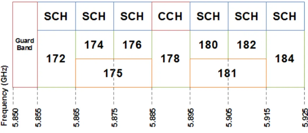
In United States, 75 MHz of spectrum in the 5.9 GHz frequency band has been allocated for Dedicated Short Range Communications (DSRC) applications. Out of the 75 MHz spectrum, 5 MHz is reserved as the guard band and seven 10 MHz channels are defined as in shown in Fig. 3.1. The available spectrum is configured into 1 control channel (CCH) and 6 service channels (SCHs). The CCH is reserved for carrying high-priority short messages or management data, while other data are transmitted on the SCHs. The pair of channels (channel 174 and 176, and channel 180 and 182) can be combined to form a single 20-MHz channel, channel 175 and 181 respectively. The channel number, indicated with (chn), is derived by counting the number of 5-MHz spectrum in the frequency
band from 5 GHz to the center frequency f (chn) of the channel chn, as following:
f (chn) = 5[GHz] + chn[GHz] (3.1)
In terms of transmitter (TX) power, four classes of devices have been defined whose maximum TX power ranges from 0 dBm to 28.8 dBm. The associated coverage distance by a single radio link depends on the channel environment, the TX power and the Modulation and Coding Schemes (MCS) used. This distance is between 10 meters to 1 kilometer. The details of OBU and RSU TX limits
of equivalent isotropically radiated power (EIRP) also depend on the operating chn channel and its applications. It is worth noting that the current FCC code
of federation regulations (CFR) heavily refers to the American Society for Test-ing and Materials (ASTM) standard E2213-03, while the industry is adoptTest-ing the IEEE802.11P and IEEE 1609 standard. The IEEE standard on the other hand refers to the FCC CFR for regulatory requirements. This means that im-plementers should address the channel and power limit defined in the ASTM standard. In detail, FCC CFR specifies that the channel 172 and 184 commonly shall be used for Public Safety Applications, as shown in [15]; this requirement is not fully compatible with the current IEEE1609.4, where multi-channel operation it is more natural to use channel 178 (i.e., the CCH) for such applications. Other than some minor differences in power level and spectrum mask requirements, ASTM standard E2213-03 and IEEE802.11P are both based on IEEE802.11A and they are effectively compatible.
Figure 3.1: The DSRC Frequency Allocation in United States
Other frequency bands have also been used for DSRC applications even before the 5.9 GHz band allocation. They were typically used for highway or city central business district (CBD) toll collection. Of particular interest are the frequency bands defined in Table 1. It is worth noting that the DSRC regulatory require-ments in many parts of the world are in the process of being finalized. There is a chance that similar spectrum allocation and requirements will be adopted World
Table 3.1: Spectrum Allocation for WAVE/DSRC Applications Country Frequency (GHz) Reference Documents North America 0.902-0.928, 5.850-5.925 FCC 47 CFR
ITU-R (ISM band)
5.725-5.875 Article 5 of Radio Regulations Europe 5.795-5.815,
5.855/5.875-5.905/5.925
ETS 202-663, ETSI EN 302-571, ETSI EN 301-893
Japan 0.715-0.725, 5.770-5.850 MIC EO Article 49
Wide for DSRC applications. Spectrum harmonization is desirable for global inter-operability and low-cost DSRC services.
3.2.1
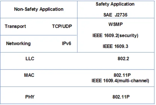
DSRC/WAVE Standards
Collectively the IEEE 1609 family, IEEE802.11p and the Society of Automotive Engineers (SAE) J2735[16] form the key parts of the currently proposed WAVE protocol stack. The WAVE protocol architecture with its major components is shown in Fig. 3.2, and they are summarized as follows.
• IEEE P1609.0 Draft Standard for Wireless Access in Vehicular Environ-ments (WAVE) -Architecture
• IEEE 1609.1 Trial Use Standard for Wireless Access in Vehicular Environ-ments (WAVE) - Resource Manager
• IEEE 1609.2 Trial Use Standard for Wireless Access in Vehicular Envi-ronments (WAVE) - Security Services for Applications and Management Messages
• IEEE 1609.3 Trial Use Standard for Wireless Access in Vehicular Environ-ments (WAVE) - Networking Services
• IEEE 1609.4 Trial Use Standard for Wireless Access in Vehicular Environ-ments (WAVE) - Multi-Channel Operations
• IEEE P1609.11 Over-the-Air Data Exchange Protocol for Intelligent Trans-portation Systems (ITS)
• IEEE802.11p Part 11: Wireless LAN Medium Access Control (MAC) and Physical Layer (PHY) specifications - Amendment: Wireless Access in Ve-hicular Environments
3.2.2
The WAVE Physical Layer (PHY)
The current FCC CFR still refers the ASTM E2213 as the PHY standard. ASTM E2213 was published in 2003, and was based on the IEEE 802.11A OFDM PHY. Since 2007 IEEE has consolidated all older versions of the PHY and the MAC into the IEEE 802.112007 edition. IEEE 802.11P [17] is an amendment to IEEE 802.11-2007 for WAVE applications. Compared to IEEE802.11-2007 [18], mini-mum change has been proposed in IEEE802.11P. In particular, IEEE802.11P only adopts the OFDM PHY on 10 MHz channels in the 5.9 GHz frequency band. On the other hand, the Wi-Fi industry normally implements the OFDM PHY on the 20 MHz channels, even though 5/10/20 MHz channels have been specified in IEEE802.11-2007. Compared to the 20 MHz Wi-Fi OFDM PHY, the subcarrier spacing and the supported data rate of IEE802.11P are halved while its symbol
Table 3.2: Comparison of WAVE and Wi-Fi OFDM Parameters
Parameters WAVE Std WI-FI Std
Frequency Band 5.9 GHz 5/2.4 GHz
Channel Bandwidth 10 MHz 20 MHz
Supported Data Rate (Mbps) 3, 4.5, 6, 9, 12, 18, 24 and 27 6, 9, 12, 18, 24, 36, 48 and 54 Modulation BPSK, QPSK, 16QAM and 64QAM Same as WAVE Channel Coding Convolutional coding
rate: 1/2, 2/3 and 3/4
Same as WAVE
No. of Data Subcarriers 4 Same as WAVE
No. of Pilot Subcarriers 12 Same as WAVE
No. of Virtual Subcarri-ers
64 Same as WAVE
FFT/IFFT Interval 6.4 S 3.2 S
Subcarrier Spacing 0.15625 MHz 0.3125 MHz
CP Interval 1.6 S 0.8 S
OFDM Symbol Interval 8 S 4 S
interval including cyclic prefix (CP) is doubled. Other parameter comparisons are shown in Table 3.2. In addition, IEEE802.11P requires the signal spectrum to decay faster to further reduce the adjacent channel interference. Different TX filtering may impact other TX performances such as Error Vector Magnitude
(EVM) to which a designer should pay attention.
The receiver design is typically out of the scope of the standard specification. However, due to significantly different channel environments, it is expected that a WAVE receiver may attract special design considerations. Compared to Wi-Fi OFDM receivers, the WAVE receivers have to deal with much higher Doppler spread which causes Inter-Carrier Interference (ICI). The fact that the sub-carrier spacing has been halved means that the WAVE OFDM receiver is more sensitive to carrier frequency offset and Doppler shift. Due to the higher Doppler spread and higher multipath delay spread, the channel coherence bandwidth and channel coherence time become smaller, or in other words, the channel becomes more frequency/selective and faster fading.
3.2.3
WAVE Medium Access Control
In the architecture of IEEE802.11 networks, three kinds of service set (SS) are de-fined: basic service set (BSS), independent BSS (IBSS) and extended service set (ESS). The IBSS is formed by stations (STAs) without infrastructure, generally called an ad-hoc network. A BSS includes an access point (AP) that behaves as the controller/master STA. The ESS is the union of two or more BSSs connected by a distribution system (DS). A STA in the IBSS acting as the controller or the access point (AP) in the BSS periodically broadcasts a beacon that contains the service set ID (SSID) and other information. Other STAs in the SS receives the beacon and synchronize their time and frequency with those contained in the beacon. STAs can communicate with each other only if they are the members of the same SS. The same architecture of SS can be used for WAVE applica-tions. However, forming a SS takes several steps including time and frequency synchronization, authentication and association. These steps take a time interval that is not affordable in some safety applications. In a vehicle traffic flow, two vehicles may be within the reach of the wireless link for less than a second. To minimize the message latency, a mode called outside the context of BSS (OCB) is introduced. The OCB mode applies to any two or more devices within the coverage area of a single radio link. A STA in OCB mode can send and re-ceive data and control frames any time without forming or being a member of any SS. While enjoying the benefit of low-latency, the OCB mode does not re-ceive the authentication, association or data confidentiality services on the MAC layer. The equivalent services have partially been moved to the higher layer as defined in IEEE1609.2. From the receivers point of view, care must be taken on frequency synchronization. Currently IEEE802.11P does not specify a different frequency accuracy for the WAVE transceiver oscillators. In IEEE802.11-2007, the frequency accuracy is specified to be 20 ppm, i.e., the maximum frequency difference between the TX and RX oscillator frequencies can be up to 40 ppm.
For example, the center frequency difference of transceivers operating on channel 184 could be as high as 5920*40*10−6= 0.2368 MHz, greater than the sub-carrier spacing of 0.15625 MHz. Without good frequency correction, the receiver error rate cannot be guaranteed even if the signal to noise ratio (SNR) is high. The
preamble can be used to estimate the frequency offset. It is likely that WAVE radios may have access to other more accurate frequency sources such as the fre-quency derived from the GPS signal. The WAVE standard also support a timing advertisement frame, which can replace some of the features lost due to the lack of periodically sent SS beacon. To transmit a frame either as a member of a SS or in OCB mode, the STA shall compete for the channel using the IEEE802.11 carrier sense multiple access/collision avoidance (CSMA/CA) mechanism. An-other major MAC layer extension for WAVE applications is the multi-channel operation defined by IEEE1609.4. This extension makes use of the concept of frequency/time division multiple access (FDMA/TDMA), where the 7 FDMA channel frequencies are as shown in Fig. 3.1. The TDMA channel is shown in Fig. 3.3. The time is divided into repetitive periods of 100 ms. During each 100ms, 50 ms is allocated to CCH and another 50 ms is allocated for SCH, in-cluding 4 ms guarding interval (GI) for switching between CCH and SCH. The motivation is to accommodate single-channel radios in the WAVE system to ac-cess both CCH and SCH services. A single-channel radio is defined as a radio that can either transmit or receive on a single 10-MHz channel but not simultaneously. On the CCH frequency (i.e., channel 178) and during CCH time (i.e., the 46 ms), only two kinds of messages can be sent: Short messages, primarily for safety applications, as defined by the WAVE short message protocol (WSMP). WAVE service advertisement (WSA) messages used to announce the services available on other SCH frequency channels.
Figure 3.3: The TDMA Extension of WAVE MAC
A single-channel radio can switch to other SCH frequencies for services during the SCH time and switch back to the CCH frequency during the CCH time for sending or receiving safety and other critical messages. The TDMA extension
does not mean that the channels are idle for about 50% of the time. All SCHs can be active all the time to exchange service data and the CCH channel can be active all the tine to exchange control, management and other short messages. Practically it does mean a loss of time for safety messages sent on the CCH frequency. It cannot be guaranteed that all other STAs shall be listening on the CCH frequency during the SCH time, and as such safety messages sent on the CCH frequency during SCH time can be ineffective. Therefore it would be desirable to concentrate all safety messages on the CCH frequency and during CCH time, i.e., only 460 ms out of a second. This represents a capacity reduction for safety messages.
3.2.4
The WAVE WSMP
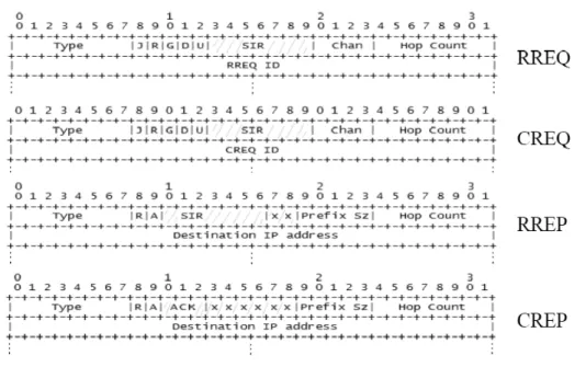
In addition to the standard IPv6 networking protocols operating over the SCHs, a WAVE-specific protocol called WSMP has been developed to carry messages on both the CCH and the SCHs. Unlike the standard IP protocol, the WSMP allows the applications to directly control the lower-layer parameters such as transmit power, data rate, channel number and receiver MAC addresses. To further shorten the latency, WSMP over the CCH can skip the steps for forming a WAVE BSS (WBSS) that delivers IP and WAVE short message (WSM) traffic on the SCHs. The primary motivation for developing the WSMP is to reduce the overload. A WSMP packet is shown in Fig. 3.4. The overhead is 11 bytes, compared to a minimum of 52 bytes of a UDP/IPv6 packet. If a device receives a WSMP packet that has a WSM Version number not supported by the device, the received WSMP packet shall be discarded.
Figure 3.4: The TDMA Extension of WAVE Medium Access Control
The Security Type identifies if the packet is Unsecured, Signed or Encrypted. The Channel Number, Data Rate and TX Power allow the WSMP to directly
control the radio parameters. The purpose of the provider service ID (PSID) field serves the similar role as the port number of the UDP/TCP packet, i.e., to identify the application that will process the WSM Data. The Length field indicates the number of bytes in the WSM Date, which might have been security-protected as specified in IEEE1609.2.
3.3
Continuous Air-interface, Long and Medium
Range (CALM)
CALM [19] is launched by the International Organization for Standardization (ISO) in 2003, and promoted by the more recently created industry association (The CALM Forum), to develop a new family of ITS standards with the over-all branding of Continuous Air-interface, Long and Medium range (CALM). The aim of CALM is to provide wide area communications to support ITS applica-tions that work equally well on a variety of different network platforms, includ-ing Second Generation (2G) mobile (e.g., GSM/GPRS), 3G (IMT-2000 e.g., W-CDMA/CDMA 1x EV-DO) 4G (IMT-Advanced), as well as satellite, microwave, millimetre wave, infrared, WiMAX and short-range technologies like Wi-Fi. The decision on which platform to use in a particular country or for a given application would then be based on logical selection of pre-set criteria (e.g., what platform is cheapest, offers highest performance, has the greatest level of coverage, and what communication equipment is available in the vehicle) to make the best use of resources. Thus, CALM is intended to be platform-independent, and therefore to avoid the battles over regional standards that have dogged existing ITS standards like DSRC.
Figure 3.5: CALM Standard logo
of the ISO, chaired by Russ Shields (Ygomi LLC, USA). The work is closely coordinated with other standards development organizations including ETSI and IEEE as well as ITU [20]. Working Group 16 has 7 sub-working groups and is currently working on nearly 20 different CALM-related standards. The main characteristics of CALM[21] are:
• Allows for continuous (or quasi-continuous) communications, in three main modes of operation: Vehicle-Infrastructure; Vehicle-Vehicle; and Infrastructure-Infrastructure.
• Inter-operability and seamless handover between networks and applications. • Based on Internet Protocol. In its initial specification, CALM used Internet Protocol version 6 (IPv6) exclusively. However, in order to meet the require-ment for very fast short communications in time-critical safety situations, such as C2C applications (e.g., collision avoidance), a non-IP solution with lower processing overhead and lower latency may be more suitable, and this is incorporated in the new specification (CALM Fast).
• A single global architecture which is compatible with existing ITS standards (e.g., DSRC) and wireless standards (e.g., GSM/GPRS) and which can anticipate future ones.
• Platform-independent support for multiple radio communication network platforms. For instance, the basic CALM system architecture (ISO 27217) foresees support for 10 main categories of network, and 22 different sub-categories, each of which would need a different Service Access Protocol (SAP).
While it is evident that not every CALM implementation would need to sup-port all of these different network platforms, the intention is to develop SAPs for each of them within the overall architecture. This multi-platform support is essential if the standard is to be global, to permit roaming and to permit seam-less interworking. Specific implementations of the standard may be customized by manufacturers to suit local conditions, market segment (e.g., compacts cars
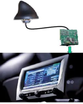
vs. luxury models), and with pre-set usage profiles (e.g., using lowest cost net-work for high bandwidth applications), and the possibility for seamless roam-ing between different service environments (e.g., urban/rural, high-speed/slow-speed/stationary) as well as between countries. CALM may be implemented in a specific device (e.g., a receiver and screen, as illustrated in Figure 3.6) or as a support for a particular service. The typical life cycle of a car, at 10-20 years, is much longer than that of a mobile phone, which can be as little as 18 months. For that reason, a technology and service-neutral approach is essential for CALM.
Figure 3.6: Example of a two part solution for in-vehicle implementation of CALM
CALM is intended to provide a standardized set of air interface protocols for ITS applications, using multiple network platforms. These include:
• 2G mobile systems, including GSM/GPRS, which are the most widely de-ployed mobile network worldwide;
• 3G (IMT-2000) mobile systems, including W-CDMA and CDMA 1x EVDO; • Infrared;
• Wireless LAN systems, including the IEEE 802.11 series; • Millimetre wave systems, including radar;
• DSRC, including national and regional implementations; • Wireless MAN systems, including WiMAX;
• Broadcast signals, including GPS and Digital Audio Broadcasting (DAB); • Personal Area Networks (PAN) including UWB and Bluetooth;
• Fixed-line networks (for infrastructure to infrastructure communications), including Fibre and Ethernet.
Figure 3.7: CALM General Architecture
The main criticism of CALM is to support so many different networks, it ends up with a bewildering array of possibilities and an over-complex manage-ment stack. However, if CALM is to reconcile the North American-originated