Abstract
This paper presents the results of a coupled longitudinal-lateral model for train dynamics. A previously developed vehicle model has been incorporated into the
TrainDy software for longitudinal train dynamics. This complex dynamic model of
the whole train has been employed to perform pushing tests and emergency braking on freight train. The reported results show that the admissible longitudinal compressive forces (LCF) are affected by the derailment criterion employed and that the pushing tests are much more severe, with respect to safety, than the emergency braking, which is a more common train operation.
Keywords: longitudinal dynamics, wheel rail contact, track switch, admissible longitudinal compressive force, train derailment, multibody train dynamics.
1 Introduction
During the common railway operations, safety conditions are prescribed and checked by limiting speed, payload, longitudinal forces exchanged by consecutive vehicles and so on; these limitations, applied to the train set, depend on the vehicle types and on the track sections, where the vehicles (and also the train) are supposed to drive. The actual limits for these parameters are prescribed by standards and regulations, imposed by National Security Agencies, based on results of several experimental test campaigns, statistically processed [1]-[4] and carried out by railway offices (e.g. ORE and ERRI). The task of determining the derailment risk of a train is a very complex problem since this risk depends on many parameters, concerning running condition, vehicle design and also the interaction between vehicles by means of buffers and draw gears, which play an important role on derailment risk, especially when a braking occurs on small radius curves.
The experimental investigation of the derailment risk, considering the overall parameters that influence the train dynamic, is often very complex and expensive; in
Paper 26
Evaluation of the Admissible
Longitudinal Compressive Forces
by Means of Multibody Train Simulations
L. Cantone, D. Negretti and V. Vullo
Department of Mechanical Engineering
University of Rome “Tor Vergata”, Italy
©Civil-Comp Press, 2012
Proceedings of the First International Conference on
Railway Technology: Research, Development and Maintenance, J. Pombo, (Editor),
order to reduce the economic effort and to let a more extensive parameter investigation, it is necessary to develop 3D numerical simulators of railway vehicles with a reliable model for wheel/rail interaction. At this aim, various numerical wheel-rail contact models have been proposed in literature by several authors [5]-[13]; they generally focus on time-saving and high-accuracy solutions for wheel-rail contact detection. Generally speaking, the approaches used to accomplish such tasks can be divided into two categories: methods based on look-up tables [5]-[6], and methods in which contact detection is computed on-line [7]-[10]. The Authors of this paper have developed a vehicle numerical simulator that falls in the latter category [14]. This simulator employs a multibody method in order to evaluate the 3D dynamics of a general vehicle, considering the most commonly used types of constraints and connections. In the last release of this simulator, more than one vehicle can be managed at the same time and their interaction is considered by means of a module that computes the three-dimensional contact and friction forces between the buffer heads and the forces due the draw gears [15]. This vehicle coupling module is also capable to consider the actual elastic characteristics of the coupling devices (with their loading and unloading speeds) along with the different heights of adjacent buffers.
Moreover, in order to accurately replicate the actual behavior of a railway vehicle running on a track, in the developed simulator, a new module called T.O.A.M. [16], that manages the three-dimensional contact between two general surfaces of wheel and rail (except for the conform contact), has been introduced. The user can define wheel and rail surfaces by means of input points taken from technical documentation or experimental measurements. This module is based on a simplified mathematical formulation that reduces the complexity of the contact problem and increases the computational efficiency. Particularly, the contact points are determined by an in-line algorithm, during the integration of the bodies’ motion, by searching the zeros of a nonlinear equation with only one variable. This module has been validated in [16] by comparing results with the ones obtained by using a commercial software (SIMPACK) and results found in literature.
The purpose of this work is to continue the previous research activity and to develop an automatic tool able to evaluate the operational limits of a vehicle, by means of pushing tests, in terms of admissible longitudinal compressive forces, using the common derailment criteria proposed by the reports [1]-[4], which are the lateral on vertical wheel force ratio (Y/Q) and the lateral force on the track (FY); even other used derailment criteria, as reported in [17], can be added in future. In this preliminary paper, only the effects of track radius and of the number of modeled multibody vehicles on the derailment risk are investigated.
Moreover, the vehicle multibody model and the vehicle coupling module, developed so far, have been added into the longitudinal dynamics software, called TrainDy [18]. This software has been initially developed by the University of Rome Tor Vergata, with the financial support of Faiveley Transport, and now it is owned by the UIC, which has further validated the code and officially certified it for longitudinal dynamic computation in January 2009. By this way, in this paper, the vehicle multibody dynamics is computed at the same time with the longitudinal dynamics of a train, performing an emergency braking on S shaped curves, having
two radii of curvature, which are, respectively, 150 m and 200 m. The aim of this investigation is to evaluate the derailment risk in an operational scenario, rather than in a fictitious operation like the pushing tests, in order to give a more realistic estimation of the derailment risk.
2 Train multibody model
In [19], some results on the effects of the longitudinal forces on the derailment risk have been already presented: in that paper, only one multibody vehicle has been modeled and the longitudinal dynamics has been taken into account by means of forces both longitudinal and lateral (the latter caused by friction between the heads buffers) applied on the buffers/draw gears of the multibody vehicle. Even if it was possible to point out the effect of these forces on the Y/Q ratio, the analysis was decoupled, i.e. the applied forces were not affected by the multibody vehicle dynamics. In [15] and in [20], pushing tests have been conducted and three multibody vehicles have been employed: also in this paper, the longitudinal forces were pre-computed and applied on the front of the first multibody vehicle and on the rear of the last multibody vehicle, being the second vehicle the one under investigation, i.e. the “candidate” for derailment, since its payload was zero. Anyway, in spite of the described approximation, in [20] several experimental comparisons have been reported.
The novelty of this paper is that the multibody (3D) model along with the tridimensional interface between consecutive multibody vehicles have been incorporated into a new version of the longitudinal dynamics (1D) software, in order to allow coupled 1D/3D dynamic analyses. It is possible to consider and to place any number of 3D vehicles along the train: of course it is meaningful to place 3D vehicles only where potentially dangerous longitudinal forces are expected. This means that it is better to run preliminary longitudinal dynamics simulations and then to decide where to place the 3D vehicles. Of course, it is possible to consider even complex operational scenarios with more than one locomotive, with delayed braking, and so on. This “upgrade” makes possible the analysis of the complete train system with the desired level of accuracy, allowed by its basic modules.
Nevertheless, there is still a simplification in the interface 1D/3D since the forces on the 3D vehicle are applied along a direction which is parallel to its longitudinal axis: this approximation will be removed in the future developments. More practically, the running forces (traction, pneumatic / electro-dynamic braking) are computed and the matrices and the generalized forces of the 3D vehicles and the 1D vehicles are assembled. The traction and braking forces applied on the 3D vehicles and computed by the 1D software are transformed into couples applied on the local reference frames of the wheelsets and of the bogies or the carbody, respectively, for bogie vehicles or axle vehicles, respecting the internal equilibrium of generalized forces. The interaction forces between consecutive vehicles are computed in two different ways: for 3D/3D vehicles the tridimensional model presented in [15] is applied; for 1D/3D interface the forces are computed considering the linear abscissa of the consecutive vehicles and then applying the formula for 1D vehicles as in [21]. As it has been already pointed out, this leads to the approximation of applying the
coupling forces on buffers and draw gears along a direction that is parallel to the vehicle longitudinal axis.
3 Admissible longitudinal compressive forces
The admissible longitudinal compressive force (LCF) is a simple parameter used to establish the limiting value of longitudinal compressive force, that can be applied on a vehicle without causing its derailment. The admissible LCF is usually computed by means of pushing tests as described in the reports [1]-[4] and it depends on vehicle type (2/4 axles), load, radius of curvature, friction among buffers heads.
The assessment of this parameter for each vehicle of a train is useful when the railways operators want to establish if a new train makeup can drive safely on a prescribed track: this means that the most of the times a new train makeup is considered safe by simply computing its longitudinal dynamics, of course, having previously assessed the admissible LCF of each vehicle.
In order to evaluate the admissible LCF of a vehicle, a derailment criteria must be employed; in this paper, two criteria are used. The first is the Nadal single wheel Y/Q limit criterion and it is used in order to avoid the flange climb derailment [17]. The limiting values used to avoid the derailment are function of the reliability probability (PA) as described in [2]; in particular the limit value Y/Q = 1.2 is related
to PA = 84% and Y/Q = 0.8 is related to PA = 95%, which means that, in actual
operative conditions, only 5% of vehicles derail if the limit value Y/Q=0.8 is used. The second criterion here used (indicated with the label “FY”) is called “Lateral displacement of the track” and prescribes the maximum lateral force applicable to the track, as function of the static axle load “P” (expressed in kN); for reinforced track this value can be computed by the Equation (1), according to [1].
(
Hlim 2)
m =25 0.6+ ⋅P (1)This criterion is used in order to avoid the track damage due to excessive lateral forces.
Following the same procedure of the reports [1]-[4], the vehicle admissible LCF is computed by means of pushing test, where the tested wagon has a payload equal to zero and the enclosing wagon are fully loaded. Besides the previous wagons the train makeup (see Figure 1) has a locomotive in front, performing an electro-dynamic braking, and another at the end of the train, pushing the train so that its speed is constant. Adjusting the traction force and the electro-dynamic braking force it is possible to apply the desired level of LCF on the tested wagon. The track employed in these tests is an S shaped curve as in Figure 2. In order to automatically compute the admissible LCF of a vehicle, according to a prescribed derailment criterion (above described) and a given operational parameter (e.g. the track radius of the S shaped curve), an iterative procedure, based on the bisection and Newton-Raphson algorithms, has been developed. This iterative procedure has been developed in order to simulate a reduced number of pushing tests, where the LCF is
changed until the prescribed derailment limit is reached, under an imposed tolerance on LCF. By this way, the evolution of the admissible LCF as function of a chosen operational parameter (e.g. the track radius of the S shaped curve) and a given derailment criterion (e.g. Y/Q = 0.8) can be drawn.
Figure 1 Train makeup used to compute the admissible LCF: TD and MB indicate, respectively, a TrainDy vehicle and a multibody vehicle.
Figure 2 S shaped curve: the curvature radii are variable; the points c, d, ... display the positions where the maximum LCF is reached during the train emergency
braking.
3.1 Tests data
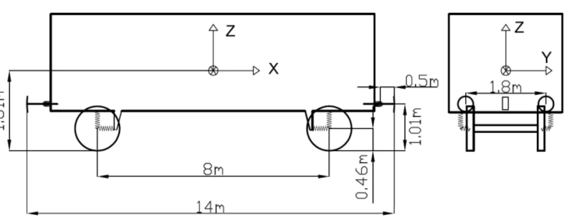
The simulated vehicle is a SNCF Gbs 254; the main geometrical characteristics of this vehicle, defined in [4] Appendix 4.1, are reported in Figure 3. In the pushing tests, all the MB vehicles are of type Gbs 254, with no payload at the central vehicle. The mass and inertia characteristics of the vehicle are reported in Table 1; moreover the elastic characteristics of the suspension are reported in Table 2. For this type of vehicle, with no payload, the criterion of FY gives a maximum value of 64 kN, according to (1). The track gauge considered in the simulations is 1435 mm; the wheel and rail profiles are, respectively, the ORE S1002 and the UIC 60.
Figure 4 shows the force-displacement characteristics of the buffers and draw gears equipping the vehicles.
Figure 3: Gbs 254 wagon geometry.
Mass [kg] Ixx [kg·m2] Iyy [kg·m2] Izz [kg·m2]
Car body 13300 32000 420000 413000
Wheelset 1490 988 90 988
Table 1: Mass and inertia characteristics of the simulated wagon.
X Y Z K [N/m] 12·106 1.4·106 970·103 C [N·s2/m] 12·104 1.8·105 640·103
Table 2: Primary suspension characteristics.
Figure 4 Force-stroke characteristics of the draw gears and the buffing gears.
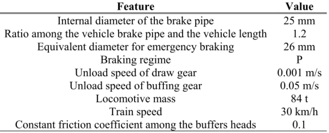
Finally, other data, useful to replicate the here presented results, are reported in Table 3.
Feature Value Internal diameter of the brake pipe 25 mm
Ratio among the vehicle brake pipe and the vehicle length 1.2 Equivalent diameter for emergency braking 26 mm
Braking regime P
Unload speed of draw gear 0.001 m/s Unload speed of buffing gear 0.05 m/s
Locomotive mass 84 t
Train speed 30 km/h
Constant friction coefficient among the buffers heads 0.1 Table 3: Data for the longitudinal dynamics simulations.
3.2 Pushing tests results
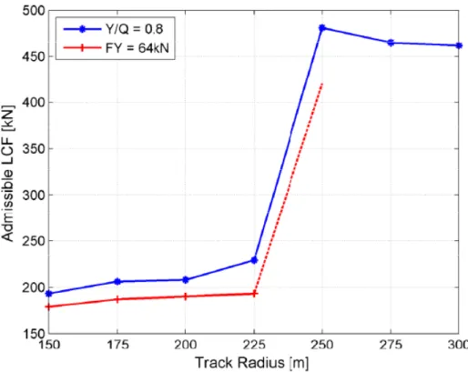
Figure 5 shows the main results of the carried out pushing tests: it displays the admissible LCF for different curvature radii and two derailment criteria, namely Y/Q = 0.8 and FY = 64 kN. For small curvature radii (up to 225 m) the two criteria give almost the same admissible LCF; above this radius, it seems that the prescribed value of FY is never reached: increasing the LCF the vehicle derails (i.e. the wheel vertical shift is above 50 mm) without reaching the desired value. As general consideration from these results, the FY derailment criterion is little more restrictive for small curvature radii and less restrictive for bigger curvature radii with respect to the Y/Q criterion. Each point on this graph is the result of more simulations until the convergence is reached; usually, 4-5 iterations are needed to achieve a tolerance of 20 kN (LCFTOL=20 kN) on the value of the LCF: i.e. when the new value of LCF, say LCF , falls in the interval new LCFold ±LCFTOL, the convergence is considered reached. It is worthwhile to mention that, with a coupled analysis like the one here presented, considering only one MB vehicle in the pushing test does not provide trustworthy results, since the adjacent TrainDy vehicles are linked to the railway track and hereby they keep the MB vehicle on the track, by means of the action of the draw gears. Of course, this behavior does not occur in a decoupled analysis, where the effect of adjacent vehicles is modeled as forces acting on the front and rear of the MB vehicle. In the development of this research activity, a more accurate investigation on the effect of the number of MB vehicles on the admissible FLC will be carried out.
A last remark on the pushing test is that, usually, the biggest Y/Q values are reached on the external wheel of the front axle, at the end of the second curve or at the beginning of the last straight track, when a part of vehicle is still on the curve. Whereas, in most of the cases, the biggest values of the FY parameter are reached towards the end of the straight track among the two curves; the location of the maximum slightly shifts towards bigger linear abscissa as the radius track increases. This means that on this type of curves this track portion needs special care during maintenance.
Figure 5 Comparison of admissible LCF vs track radius (see also Figure 2), considering Y/Q = 0.8 and FY = 64kN as derailment criteria.
3.3 Emergency braking
Pushing tests are not common railway operation; more common, even if not ordinary, is the emergency braking. In this paragraph, the comparison among the Y/Q ratio obtained during an emergency braking (from 30 km/h to a complete stop) and the corresponding value obtained with a pushing test is carried out. In order to achieve this task, the train makeup displayed in Figure 6 is employed: the wagons have a payload of 30 t or are empty; also the mass of the locomotive is changed so that its weight is the same of a full loaded vehicle. The overall number of vehicles is 30 and the maximum LCF is reached in the middle of the train as displayed in Figure 7, which refers to an emergency braking on a straight track. This value is almost the same as the admissible LCF, reported in Figure 5 for the Y/Q=0.8 derailment criterion.
The train operation is changed so that the center of mass of the 15th vehicle is placed at the position displayed with c, d, ... in Figure 2; in order to achieve this task, it has been necessary to change the initial position of the first vehicle on the track and to start the emergency braking after a number of seconds, especially to obtain the maximum of LCF at the position f and g. The Table 4 reports the maximum values of Y/Q and, for completeness, of FY reached on the 15th vehicle when the maximum of LCF in obtained at the positions c, d, … of the centre of mass of the vehicle 15th.
F rea sec on em ma Figure 7 Ti Table 4: M As already ached when cond curve, the straight mergency br aximum is Figure me evolutio Figur Maximum va y remarked n the front whereas, th t track amon raking tests reached. A e 6 Train ma on of LCF f re 6, using t Positio c d e f g alues of FY in the pre wheelset o he maximu ng the two c s give the Anyway, ke akeup for em for an emerg the data pro
on FY [kN 24,1 20,2 48,0 31,1 18,7 and Y/Q fo positions. evious sect of the testin um of FY is curves. This same resu eeping the mergency b gency braki ovided at par N] Y/Q 0,27 0,27 0,37 0,55 0,39 or emergenc tion, the m ng vehicle s reached w s means tha ults in term same maxi braking.
ing and train r. 3.1.
cy braking,
maximum of is around t when the tex at the pushin ms of positi imum value n makeup o at different f Y/Q ratio the end of xting vehicl ng tests and ion where e of LCF, f t o is the le is d the the the
pushing tests provide bigger values of Y/Q and FY with respect to the emergency braking tests, because the value of LCF is kept for less time in the latter tests. As a consequence, the admissible LCF values of pushing tests are computed privileging the safety.
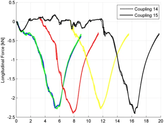
Figure 8 Time evolution of LCF for different emergency braking positions: c blue, d green, e red, f red, g black.
As last result, Figure 8 shows the time evolution of LCF when the maximum is reached at the positions c, d, ... : as it is clear, the LCF slightly changes on a curve with respect to its value achieved on a straight track and its percentage difference is around 10 %.
4 Conclusions
By implementing an already developed and verified multibody vehicle model in the
TrainDy software for the train longitudinal dynamics, it has been possible to carry
out “coupled” longitudinal-lateral dynamic analyses of a trainset. Coupled in this context means that, for example, the train pneumatics are computed at the same time as the wheel-rail contact. This complex model enables the computation of the admissible LCF of every railway vehicle, which can to be next used for the assessment of new train makeups. The reported results prove that the chosen
derailment criterion affects considerably the admissible LCF, when pushing tests are employed; in turn, such tests represent an operation scenario that is much more critical, from the safety point of view, than the emergency braking. This means that the practice of these types of tests is a benefit for railway safety.
References
[1] ORE Question B 12, Report No. 40, “Propelling tests with long two-axle
wagons”, Utrecht, April 1984.
[2] ORE Question C 138, “Permissible maximum values for the Y- and Q- forces
and derailment criteria”, Utrecht, September 1986.
[3] ORE DT 97 (C138) E, “Statistical evaluation of derailment tests in derby
(September, 1977) with two-axled goods wagon”, Utrecht, February 1979.
[4] ERRI B 12/RP 58, “Relative to two-axle wagons in train formation and
negotiating track sections with small-radius s-curves and short straight intermediate sections, studies of the permissible longitudinal compressive forces resulting from braking forces and pushing forces from low speeds”,
Utrecht, January 1994.
[5] L. Cantone, D. Negretti, F. Vivio, and V. Vullo, A simplified model of
wheel-rail contact geometry. Congreso Internacional Conjunto XXI Ingegraf – XVII
ADM, 10-12 June 2009.
[6] M. Malvezzi, E. Meli, S. Papini, L. Pugi, and M. Rinchi, A railway vehicle
multibody model for real – time applications. Vehicle System Dynamics,
46/12, 1083 – 1105, 2008.
[7] J. Auciello, S. Falomi, M. Malvezzi, E. Meli, and P. Toni, Determination of
wheel/rail contact points in the simulation of a railway vehicle dynamics.
Springer Science+Business Media B.V., 2008.
[8] J. Auciello, E. Meli, S. Falomi, and M. Malvezzi, Dynamic Simulation of
railway vehicles: wheel/rail contact analysis. Vehicle System Dynamics, July
2009, Vol. 47, No. 7, pp. 867-899.
[9] S. Falomi, M. Malvezzi, E. Meli, and M. Rinchi, Multibody modeling of
railway vehicles: innovative algorithms for the detection of wheel-rail contact points. 2009, 8th International Conference on Contact Mechanics and Wear of
Rail/Wheel Systems (CM2009), Firenze, Italy.
[10] J. Pombo, J. Ambrósio, and M. Silva, A new wheel–rail contact model for
railway dynamics. Vehicle System Dynamics, 45/2, 165 – 189, 2007.
[11] H. Sugiyama and Y. Shda, On the Contact Search Algorithms for wheel/Rail
Contact Problems. Journal of Computational and Nonlinear Dynamics,
Ocober 2009, Vol. 4
[12] P. Shackleton and S. Iwnicki, Comparison of wheel-rail contact codes for
railway vehicle simulation: an introduction to the Manchester Contact Benchmark and initial results. Vehicle System Dynamics, January-February
2008, Vol. 46, Nos. 1-2, pp. 129-149.
[13] A. A. Shabana, K. E. Zaazaa, and H. Suguyama, Railroad Vehicle Dynamics A
computational approach. CRC Press, Taylor & Francis Group, New York,
[14] L. Cantone, D. Negretti, L. Vita, V. Vullo, “Effect of train longitudinal
dynamics on wheel-rail forces”, 8th International Conference on Contact
Mechanics and Wear of Rail/Wheel Systems (CM2009), Firenze, Italy, September 15-18, 2009.
[15] L. Cantone, D. Negretti, V. Vullo “Modello tridimensionale dei tiranti e del
contatto tra i respingenti nell’interazione tra veicoli ferroviari contigui”,
AIAS XL, 7-9 Settembre, Palermo, 2011.
[16] D. Negretti, “A third-order approximation method for threedimensional
wheel–rail contact”, Vehicle System Dynamics, DOI:
10.1080/00423114.2011.595804, 2011.
[17]
S. Iwnicki, Handbook of Railway Vehicle Dynamics, CRC Press, Boca Raton, 2006.[18] L. Cantone, L. Müller, D. Negretti, V. Vullo, “TrainDy, new UIC simulator
for longitudinal dynamics of trains”, CompRail 2008, 15-17 Settembre
Toledo, 2008.
[19] L. Cantone, D. Negretti, L. Vita, V. Vullo, Effetto della dinamica
longitudinale sulle forze di contatto ruota rotaia, AIAS XXXVIII, 9-11
Settembre, Torino, 2009.
[20] L. Cantone, D. Negretti, V. Vullo, Wheel rail contact and longitudinal lateral
interaction between vehicles on train dynamics, CC2011 6-9 September,
Chania, Creta, 2011.
[21] L. Cantone, TrainDy: the new Union Internationale des Chemins de Fer
software for freight train interoperability, Proc. IMechE, Part F: J. Rail and