Andrea Vinci
A Cloud-Assisted Agent-Based
Framework for Cyber-Physical
Systems
and its applications
Ph.D. Thesis
Aknowledgements
Firstly, I would like to express my sincere gratitude to my advisor, professor Giandomenico Spezzano, for his expert guidance and for allowing me to grow as a researcher.
I would like to thank my colleagues, Andrea Giordano, for all the work done together, for his advices and for the exhausting but stimulating discussions, and Alessia Amelio, for her support during my PhD studies and for her advices in both research and life.
I thank all my colleagues and friends at ICAR and Unical, for the stimu-lating discussions and for all the fun we have had in the last three years.
I would like to thank my parents and my brother for supporting me spiri-tually throughout writing this thesis and my life in general.
Finally, I would like to thank Anna, for her support, presence, patience and love, and Lara, whose smiles light my way even during the hardest times.
Preface
Since the early 2000s, we have experienced a disruptive trend in the inte-gration of information and communication technologies with physical objects and systems which can potentially change, and sometimes already has, the way people live and interact with the physical world. The same trend affects engineered systems, which can exploit embedded networking and computa-tion devices to improve their efficiency and capabilities, as well as physical infrastructures and environments, which can be augmented with sensing, ac-tuation, computational and networking capabilities, so as to became “smarte” systems, acquiring an autonomous behaviour or providing new services and functionalities to their users, either human or other systems.
When a system encompasses a large number of physical devices, each with computational and networking capabilities, being seamlessly integrated with a physical environment and capable of sensing and/or changing its status, and when all these devices cooperate with the others so as to provide a certain physical behaviour or new service and functionalities, that system can be called a cyber-physical system (CPS) [7].
According to NSF[93], research advances in cyber-physical systems promise to transform our world with systems that respond more quickly (e.g., au-tonomous collision avoidance), are more precisely (e.g., robotic surgery and nano-tolerance manufacturing), work in dangerous or inaccessible environ-ments (e.g., autonomous systems for search and rescue, firefighting, and explo-ration), provide large-scale, distributed coordination (e.g., automated traffic control), are highly efficient (e.g., zero-net energy buildings), augment human capabilities, and enhance societal well-being (e.g., assistive technologies and ubiquitous healthcare monitoring and delivery).
This vision lays down a challenge for new frameworks, models and algo-rithms to be proposed, so as to support the design of these kinds of complex system, taking into account their requirements and related issues such as adaptivity, devices heterogeneity, large-scale, reconfiguration, responsiveness, decentralization and reliability.
1. the definition of a cloud-assisted, agent-based framework for designing large-scale Cyber Physical Systems, tackling issues like heterogeneity, scal-ability and reconfigurscal-ability;
2. the proposal of models and patterns for the design and implementation of CPS, through the use of decentralized agent-based algorithms in various application scenarios;
3. the proposal of a decentralized control system for urban drainage net-works, which can improve the performance of an existing network reducing its environmental impact.
The rest of this thesis is structured in four chapters, as follows:
Chapter 1 presents the fundamental concepts of Cyber-Physical Systems, characterizing them, highlighting open issues and presenting possible ap-plication scenarios.
Chapter 2 is devoted to present Rainbow, a cloud-assisted, agent-based plat-form for Cyber-Physical Systems, detailing its main components and fea-tures.
Chapter 3 shows how the Rainbow platform can be exploited in multiple ap-plication scenario, using proper decentralized algorithms and cooperation mechanism.
Chapter 4 presents a methodology for managing an urban drainage network, seen as a Cyber Physical System, so as to provide an optimized behaviour to the system, which is capable of reducing effectively both urban flooding and combined sewer overflow phenomena, as well detailed in the experi-mental section.
Contents
Preface . . . 5
1 An introduction to Cyber-physical Systems . . . 13
1.1 Introduction . . . 13
1.2 Enabling Technologies . . . 15
1.2.1 Hardware miniaturization and energy efficiency . . . 16
1.2.2 Networking technologies . . . 16
1.2.3 Computer science . . . 17
1.3 Applications . . . 18
1.3.1 Energy Systems . . . 18
1.3.2 Transportation systems . . . 19
1.3.3 Healtcare and medical Systems . . . 19
1.3.4 Hydraulic infrastructures . . . 20
1.3.5 Home automation and ambient assisted living . . . 20
1.4 Challanges . . . 20
1.4.1 Heterogeneity . . . 20
1.4.2 Scalability . . . 21
1.4.3 Reconfigurability . . . 21
1.4.4 Cooperation models . . . 21
1.4.5 Human in the loop . . . 22
1.5 Conclusions . . . 22
2 A Smart Platform for Large-Scale Cyber-Physical Systems 23 2.1 Introduction . . . 23
2.2 Related work . . . 25
2.3 Rainbow architecture . . . 27
2.3.1 Virtual Objects . . . 29
2.3.2 Rainbow Multi Agent system . . . 31
2.3.3 Cloud layer . . . 35
3 Rainbow in action . . . 37
3.1 Introduction . . . 37
3.2 Floor control . . . 37
3.3 Noise pollution mapping . . . 42
3.4 Smart Home . . . 44
3.4.1 Knowledge discovery workflow . . . 45
3.4.2 Ambient assisted living . . . 46
3.5 Smart Street Cosenza . . . 49
3.6 Conclusions . . . 50
4 A cyber-physical system for urban drainage networks . . . 53
4.1 Introduction . . . 53
4.2 Methods . . . 55
4.2.1 The structure of an urban drainage system . . . 55
4.2.2 Drainage network instrumentation . . . 55
4.2.3 Distributed control of urban drainage network . . . 56
4.2.4 SWMM . . . 64
4.3 Results and discussion . . . 66
4.3.1 The case study: the sewer system of the city of Cosenza 66 4.3.2 Experimental setup . . . 67
4.3.3 Experimental results . . . 68
4.4 Conclusions . . . 74
Conclusions and outlook . . . 77
List of Figures
1.1 Internet of Things versus Cyber-Physical Systems. . . 15
2.1 Rainbow architecture. . . 28
2.2 Example of binary tree of a rule. . . 30
2.3 Rainbow multi-agent entities. . . 32
2.4 Forwarding mechanism . . . 33
2.5 Rainbow cloud layer. . . 36
3.1 Floor topology. . . 38
3.2 Rooms assignment to computational nodes . . . 40
3.3 Logical distribution of agents in the floor. . . 41
3.4 Deployment of the agents and their physical distribution on the computing nodes. . . 42
3.5 Activity recognition tasks flow . . . 46
3.6 Case study main flow . . . 47
3.7 Smart Street Cosenza: target areas. . . 50
3.8 Smart Street Cosenza . . . 51
4.1 The down-hinged movable gate . . . 56
4.2 Drainage network structure . . . 57
4.3 Sub-networks in a realistic case . . . 58
4.4 Gates positions . . . 60
4.5 Agents in generated networks . . . 61
4.6 PID controller . . . 63
4.7 Snapshot of the SWMM software . . . 65
4.8 SWMM customization . . . 66
4.9 Urban drainage system of Cosenza, Italy . . . 67
4.10 CSO reduction vs. rainfall event average intensity. . . 70
4.11 Flow Rate vs. Time using Scenarios 0-4 . . . 72
4.12 CSO and Flooding reduction vs. Scenario using the rainfall event of 24th March 2014. . . 73
4.13 CSO and Flooding reduction vs. Scenario using the rainfall
event of 30th January 2015. . . 73 4.14 CSO and Flooding reduction vs. Scenario using the rainfall
List of Tables
3.1 Virtual Door. . . 39
3.2 Virtual Chair. . . 39
3.3 Virtual Wall. . . 39
3.4 Virtual Desk. . . 39
4.1 Hydrological and hydraulic characteristics of the selected rainfall events. . . 68
1
An introduction to Cyber-physical Systems
1.1 Introduction
Over the last two decades, the advancements in computing and communica-tion technologies have been so significant that have given rise to an informacommunica-tion technology (IT) revolution. The Internet has changed the way we interact and communicate each other and also how we create, distribute and consume infor-mation. Furthermore, the advent of ubiquitous embedded computing, sensing, and wireless networking technologies has also changed how we interact, con-trol, and build physical engineered systems such as automobiles, aircrafts, power grids, manufacturing plants, medical systems and building systems, on which our modern society and economy are becoming highly dependent.
The potential benefits of the convergence between the cyber-world, i.e. computation and networking, and the physical world for developing new en-gineered systems are transformative and wide ranging. Through embedded systems for distributed sensing, computation and actuation over wired or wireless communication networks, multi-objective optimization and high level decision-making algorithms, engineered systems in many application domains, such as transportation, energy, domotic and medical systems, can be designed and developed to be much smarter, more reliable, secure, efficient and robust. Recently, we have experienced an ongoing seamless integration between the cyber and the physical worlds, at every scale. Everyday objects can be enhanced with computation and networking capabilities, so as to provide ad-ditional features, like facility to notify a change of status to a remote server and to be remotely controlled by smartphones. These so-called smart objects can even execute simple tasks, such as keeping a given temperature in a room or dispensing the correct amount of water in the soil to keep the right humid-ity for the health of a vegetable. Smart Objects are the building blocks of the Internet of Things (IoT) vision [44].
The Internet of Things[52] is the network of physical objects, or “things” , embedded with electronics, software, sensors, and network connectivity, which enables these objects to collect and exchange data. IoT can be seen as a
realization of the concept of ubiquitous computing, proposed by Mark Weiser in the early ’90s [90].
When a set of these networked things are placed in the same environment and cooperate to provide new functionalities or to achieve a common goal, it is possible to extend the abstraction of smart objects so as to define smart environments. In the literature, there are many different definition of smart environment, among them: (i) “a small world, where all kinds of smart devices are continuosly working to make inhabitants’ lives more confortable”[20] and (ii) “an environment that is able to acquire and apply knowledge about the environment and its inhabitants, in order to improve their experience in that environment ”[94].
Besides and in parallel with the IoT vision, the engineering research field of cyber-physical systems (CPS) has attracted a great deal of attention from academia, industry and governments. As a whole, CPSs can be described as “smart systems that encompass computational (i.e., hardware and software) and physical components, seamlessly integrated and closely interacting to sense the changing state of the real world ”[93], or even as the “next generation of engineered systems that require tight integration of computing, communica-tion, and control technologies to achieve stability, performance, reliability, ro-bustness and efficiency in dealing with physical systems in many application domains” [66].
CPSs are different from desktop computing, traditional embedded/real-time systems, and Wireless Sensor Networks; however, they have some defining characteristics as follows[84]:
• Cyber capability in every physical component and resource constraint. The software is embedded in every embedded system or physical component, and the system resources (e.g., computing and network bandwidth) are usually limited.
• Closely integrated. CPSs deeply integrate computation with physical pro-cesses.
• Networked at multiple and extreme scales. CPSs, the networks of which in-clude wired/wireless network, Wi-Fi, Bluetooth, and GSM, among others, are distributed systems. Moreover, the system scales and device categories appear to be highly varied.
• Complex multiple temporal and spatial scales. In CPSs, the different com-ponents are likely to have unequal granularity of time and spatiality. CPSs are strictly constrained by spatiality and real-time capacity.
• Dynamically reorganizing/reconfiguring. CPSs, as very complicated and large-scale systems, must have adaptive capabilities.
• Closed-loop control and high degrees of automation. CPSs favor convenient man-machine interaction, and advanced feedback control technologies are widely applied to these systems.
1.2 Enabling Technologies 15
• Operation must be dependable and certified in some cases. Reliability and security are necessary for CPSs because of their extreme scales and complexities.
IoT and CPS research topics share similar goals and technologies but have different research communities and focus on different approaches and prob-lems. Both of them concerns large-scale distributed computing systems of systems, where computation and “intelligence” is not decoupled from the en-vironment. Conversely, while the IoT focuses on openness, interoperability and cooperation of objects in dynamic environments, whose elements contin-uously change over time, CPSs focus on more “static environments”, where interactions take place between well-known and controlled participants. A typical CPS is often an engineered closed-loop controlled system, even though networked and with bigger scale.
For a better understanding of the different visions, we can look at Figure 1.1. While the Internet of Things is about extending the existing Internet so as to connect the objects in the physical world, a CPS is an application-specific system that integrates cyber and physical components to achieve a certain goal.
Fig. 1.1. Internet of Things versus Cyber-Physical Systems.
1.2 Enabling Technologies
The integration between the cyber and the physical world is made possible due to recent advancements in microelectronics, telecommunication systems, em-bedded systems, communication protocols and computer science, as detailed in the following.
1.2.1 Hardware miniaturization and energy efficiency
Traditionally, computing devices were stationary and mains powered, which meant processor units being designed with computing performance as the main goal. Since the early 2000s, with the end of Dennard Scaling[25, 35] and the growth of the demand for mobile devices, manufacturers have switched their focus from computational power to energy efficiency[22]. Nowadays all the main manufacturers produce devices and systems-on-a-chip that can be suitably embedded in objects and things (as well as in smartphones), thanks to their small form factor and low energy consumption. Obviously, the com-putational power of these kinds of device is not comparable with a desktop or server computer, but is enough to provide general purpose computational capabilities to an embedded object.
1.2.2 Networking technologies
Cyber-physical systems are built using networked components, which can be spread over small areas, like a room or an house, or wider areas, as a sewer network or a power grid. The telecommunications industry and research com-munity developed new technologies that enable reliable wired and wireless con-nectivity both in wide area domains and in small area ones. Wireless internet connectivity is granted world-wide by digital cellular networks, whose tech-nologies and standard evolved from the first digital mobile system (2G), pro-viding more and more bandwidth [24]. The current standard, LTE-Advanced, is expected to offer peak rates up to 1 Gbit/s fixed speeds and 100 Mb/s to mobile users[76]. In a local area network, wireless connectivity is reached us-ing the IEEE 802.11 standard. The current iteration is IEEE 802.11ac, which is an advancement in terms of both maximum transmission data rate and energy consumption[58]. Furthermore, the IEEE 802.11ah amendment is cur-rently in a draft state, aiming at achieving a transmission range of up to 1 km at the minimum data rate of 100 kbps and low power consumption, so as to be used in wireless sensor networks and IoT on even an urban scale. In personal area networks, the reference is currently represented by ZigBee and Bluetooth specifications. The former is a low-cost, low-power, wireless mesh network standard targeted at wide development of long battery life de-vices in wireless control and monitoring applications[11] and is widely used in home automation applications. The latter provides a bigger data rate com-pared to ZigBee, at the cost of lesser transmission range and greater energy consumption[37]. Bluetooth is mainly used to establish single-hop connection between two devices for exchanging multimedia streams/data.
Given the large number of devices that can be involved in a CPS, other networking issues that need to be dealth with are the unique identification and the addressability of the devices. Back in 1999, the term ”Internet of things” was firstly introduced by Ashton [8] in a presentation about Radio Frequency Identification (RFID)[89] technology. He show how easily a computer can
1.2 Enabling Technologies 17
recognize objects that are attached with proper RFID tags, using a proper reader. The Electronic Product Code Tag Data Standard (EPC TDS)[77] specifies what information is encoded on an RFID tag to uniquely identify a certain object, together with some additional product information. Extensions to this standard are proposed, for example in [75], to better full-fill the needs for openness and interoperability of the Internet of Things.
The addressability issue is dealt with using the Internet Protocol Version 6 (IPv6), which has a larger address space than IPv4. The length of an IPv6 address is 128 bits, therefore, the address space has 2128 or approximately
3.4 ∗ 1038 addresses, thus being more than sufficient for meeting the need of
unique addresses for the next decades. Furthermore, the previously mentioned ZigBee and Bluetooth specifications provide extensions to integrate their stack with the IPv6 protocol[88, 71].
1.2.3 Computer science
Enabling technologies from a computer science perspective cover a wide range of research area. Back in 1946, the scientists behind the first computer devel-oped it to perform ballistic computations. The first general purpose computer, ENIAC (Electronic Numerical Integrator and Computer) was capable of per-forming all the four basic mathematical operations plus the square root, using as working memory twenty accumulators, each of which were capable of stor-ing a ten-digit decimal number. Actually, the first computers were targeted to do mathematical computation, and their only requirement was the cor-rectness of the results. When they began to be used to close control loops around physical systems, only correctness was not enough, since time related issues have to be taken into account. This motivated the development of real-time computation[82, 50], which involved the problems of how to schedule computational tasks so that every job in every task is completed before its deadline. Many cyber-physical systems applications involve automation and actuation to a distributed physical environment with soft or hard real time constraints[43].
Cyber-physical systems can be seen also as a natural evolution of Wireless Sensor Networks (WSN). Under the flag of the Smart Dust[69] project, it was given the concept of mote, which is a tiny device capable of sensing, compu-tation and communication. These motes allowed the attachment of sensors to the nodes, bringing information about the physical environment into the interconnected wireless sensor network [92] of computational nodes. When the nodes in a communication network are connected both to sensors and actua-tors, one obtains a Wireless Sensor and Actuator Network (WSAN)[87], which can be seen as a networked control system very similar to the concept of CPS. Each device involved in a CPS can produce data about its internal state and measures about the environment in which it is deployed at a very high rate, thus techniques are needed to manage the huge amount of data coming from all the devices involved in a large-scale system. Traditionally, computing
on data requires (i) the data to be completely stored somewhere and available as a whole and (ii) programs that are able to compute on a large piece of input data. When the data size is overwhelming, as in CPSs, smarter techniques need to be used, and the precision of results can be sacrificed in order to meet time and space requirements. Models and algorithms for dealing with these so-called data streams are surveyed, for example, in [55] and [4], where data streams are formally defined and algorithms are presented for statistical aggregation and for data mining tasks.
A data stream processing algorithm is an on-line algorithm that pro-duces/updates the result as soon as a new element arrives from a stream. This requires that the algorithm can process each element only once (or a fixed number of times), then the processed element must be dropped. On the contrary, in some applications there is the need to store the data for further analysis and future uses. The ”Big Data”[18] research topic refers to the col-lection of techniques that tackles the issues of storing, computing and mining on this kind of huge data-set, and there is a growing attention in the CPSs research community to this subject [47].
1.3 Applications
The effect of CPS research can be significant in many application domains, where large scale systems can exploit a closer integration between computa-tion and physical processes so as to obtain new control funccomputa-tionalities and capabilities, or improvements in efficiency, reliability and adaptivity.
1.3.1 Energy Systems
Energy generation, transmission, and distribution for a clean and sustainable society are high-priority issues that are currently being investigated by both the industry and the scientific community.
Power electronics, power grid and embedded control form a CPS, whose design is heavily influenced by fault tolerance, security, decentralized con-trol and economic, ethical and social aspects. The smart grid[6] is a next-generation infrastructure for electric power systems that can help to produce, distribute and use electricity in a cleaner, more cost effective and efficient manner through the integration of computing, communication and control technologies. The production and distribution of electric energy can be made more responsive and reliable through real-time distributed sensing, measure-ment and analysis. Furthermore, communication and information technology can contribute to improving the efficiency of overall electric consumption by encouraging consumers to avoid consumption peak times through a dynamic pricing mechanism and by providing useful real-time price information to consumers. Thanks to the infrastructure and mechanism for bidirectional ex-change of information and electricity, smart grids allow traditional electric
1.3 Applications 19
energy consumers to become providers. Electric energy that is stored or gen-erated at residential and industrial facilities from renewable energy sources such as wind and solar power can be sold to other consumers in the neigh-bourhood or electric power providers. Recent advancement in CPSs for smart power grid are presented, for example, in [42].
Computing, communication, and control technologies can play an impor-tant role in improving efficiency in the home and in office building energy consumption. Appliances, lighting and HVAC (heating, ventilating and air conditioning) can be more efficiently managed through distributed sensing, by monitoring inhabitants behaviour and dynamically reacting to human ac-tivities and weather conditions[83, 95].
1.3.2 Transportation systems
The development of vehicles, mass transit, and traffic systems to address sus-tainability, efficiency, congestion and safety is an important research issue for the benefit of our environment, economy and safety. Next generation trans-portation systems can potentially integrate intelligent vehicles and intelligent infrastructures. Intelligent vehicles can be equipped with seamlessly integrated embedded computing systems and in-vehicle networking systems. Vehicles can exchange information through wireless communication between vehicle to ve-hicle and veve-hicle-to-infrastructure. Intelligent mass traffic systems can be more adaptive to the needs of users. Through these capabilities, vehicles can assist drivers or even drive autonomously by monitoring and estimating traffic con-ditions, planning ahead their behaviour, and implementing the plan through drive-by-wire functionalities such as stability control, speed control, braking and steering. Intelligent traffic infrastructures can be operated to manage the throughput of entire traffic systems. Intelligent mass transit systems can be better adaptive to the need of users.
1.3.3 Healtcare and medical Systems
It is an important challenge to design and develop medical devices and sys-tems with better efficiency, reliability, intelligence, and interoperability. Med-ical devices need to be highly reliable; moreover, they should be operated in a patient-specific manner since patients have different physiological charac-teristics. Formal models of patient physiological dynamics, and the hardware and software systems of medical devices, and their interactions, can play an important role in designing and verifying the safety properties of devices. The integration of wireless networking and distributed sensing and computing in-frastructure for interconnectivity and interoperability with medical devices enables the development of medical systems by which patient physiological conditions can be diagnosed and treated in a more integrated and intelligent manner.
1.3.4 Hydraulic infrastructures
Urban hydraulic infrastructures such as water supply or drainage systems, can benefit from CPSs so as to make them capable of autonomously adapting to exceptional events. Water supply systems, when properly equipped with actuation components, such as pump and gates, and sensors monitoring the state of the pipelines, can react to pipeline breakages or pressure drops, so as to favour high-priority buildings such as hospitals or schools. Drainage systems can use their storage capacity more efficiently, for reducing or avoiding urban flooding even when heavy rainfall events occur.
1.3.5 Home automation and ambient assisted living
Improving the quality of life for the disabled and the increasing proportion of elderly people is becoming a more and more essential task for today’s societies. One way to achieve this goal is by making the home environment a more com-fortable place to live in, equipping it with sensors and actuators devices that can be used for monitor and automation tasks. The elderly or physically dis-abled people can be continuously monitored, and their daily activities can be properly recognized using relevant sensors data and classification techniques. Predictive algorithms can be used to anticipate inhabitants’ behaviour so as to forecast their needs and properly control light and appliances. Exceptional or risky situations, such as a fall or diseases, can be recognized too, so as to immediately send alarms to relatives or doctors, and switch off potentially dangerous appliances.
1.4 Challanges
Owing to their inherent complexity, the design of CPSs is faced with several challenges and issues, as described in [66][74][16][54].
1.4.1 Heterogeneity
Owing to the nature of many of the possible application contexts, there is the need to coordinate a large number of heterogeneous devices. If a CPS is designed for enhancing an existing system, most of the hardware devices previ-ously involved can still be used in the new system, and only small changes are allowed. Devices can be heterogeneous in different ways. There are devices with no computational power on board, that are only simple electronically controllable sensors or actuators, and more sophisticated, ”smart” devices, with little or even high computational power on board. Among the latter, devices can run different operating system, from embedded OS, as TinyOS, to linux-based or android-based systems. Furthermore, devices can be capable
1.4 Challanges 21
of communicating each with a different protocol, which can be even a propri-etary one. In order to cope with this heterogeneity, integration techniques are needed, so as to allow all the devices involved to be capable of interact among themselves and with all the components of the CPS.
1.4.2 Scalability
As CPS may involve large physical infrastructures like transportation systems or power grids, a large number of physical entities have to be suitably moni-tored and controlled. Furthermore, a lot of physical applications are subject to different operating conditions, and the number of signals/measures being produced and managed can increase or decrease over time. As a result, there is the need to search for solutions which can scale, allowing a system to operate correctly and efficiently even under unexpected load peaks. This is more and more important for highly-critical systems, such as power grids and hydraulic networks.
1.4.3 Reconfigurability
In its lifespan, a cyber-physical system can change over time. New elements or devices can be added, e.g. when an urban infrastructure covers a new area, also obsolete or no longer needed elements can be removed. Furthermore, existing ”smart” elements can need a software update or be physically repaired. When these changes involve highly-critical systems, a total shut-down for a scheduled maintenance can be not possible. A CPS must to be reconfigurable with little or no interruptions in its operations, reducing inefficiencies to a minimum
1.4.4 Cooperation models
Many existing systems exploit a centralized controller, which collects the mea-sures generated from sensors, processes them so as to produce an actuation plan, and then transmits the appropriate signals to all the actuators. When the system requires coordination of a large number of devices, time constrained processing, and bandwidth limitations, this model does not perform well. De-centralized cooperation models can be better exploited, where each device be-haves autonomously on the basis of its local status and exchanges information with others. Swarm intelligence and bio-inspired strategies can be suitably ex-ploited for controlling a system in a decentralized fashion, and for the design of distributed and decentralized clustering and pattern detection algorithms1
that can support the autonomous decisions of the elements involved.
1
Spezzano, G., Vinci, A. (2015). Pattern Detection in Cyber-Physical Systems. Procedia Computer Science, 52, 1016-1021.
1.4.5 Human in the loop
In many application domains the operation of a CPS involves a closely inter-action with people. These interinter-action can be indirect, when the behaviour of a system changing the status of an environment affects the people behaviour (and viceversa), and direct, when these interactions are designed to be part of the behaviour of a system, as in the Smart Home Environment scenario. These interactions have to be properly modelled, and communication mechanisms between human and CPS need to be designed, using graphic applications as user interface directly embedded on systems devices, web site portals, or even exploiting existing human oriented systems as social networks2.
1.5 Conclusions
In this chapter, Cyber Physical Systems were over-viewed, defined as smart systems that encompass computational and physical components, seamlessly integrated and closely interacting to sense the changing state of an environ-ment. Technologies enabling this vision have been summed up, and possible innovative applications listed. Finally, CPSs requirements and challenges, in-volving heterogeneity, scalability, reconfigurability and decentralization have been detailed. In the next chapter, a novel platform for large scale CPSs will be presented, providing solutions to the issues summarized in this chapter.
2 Giordano, A., Spezzano, G., Sunarsa, H., Vinci, A. (2015, May). Twitter to
in-tegrate human and Smart Objects by a Web of Things architecture. In Computer Supported Cooperative Work in Design (CSCWD), 2015 IEEE 19th International Conference on (pp. 355-361). IEEE.
2
A Smart Platform for Large-Scale
Cyber-Physical Systems
12.1 Introduction
The increasing use of smart devices and appliances opens up new ways to build applications that integrate the physical and virtual world into consumer-oriented context-sensitive Cyber-Physical Systems (CPS) [46, 74, 45] enabling novel forms of interaction between people and computers. CPS are combina-tions of physical entities controlled by software systems to accomplish specified tasks under stringent real-time and physical constraints.
The emerging cyber-physical world interconnects a vast variety of static and mobile resources, including computing/medical/engineering devices, sen-sor/actuator networks, swarm of robots etcetera. Examples of CPS applica-tions include [84] traffic control, power grid, smart structures, environmental control, critical infrastructure control, water resources and so on. These sys-tems could be pervasively instrumented with sensors, actuators and computa-tional elements to monitor and control the whole system. Furthermore, these devices should be interconnected so as to communicate and interact with each others and with people.
This scenario is supported by recent technology advancement in the fields of communication, embedded systems and computer science.
1- Giordano, A., Spezzano, G., Vinci, A. (2014). Designing Cyber-Physical
Systems for Smart Infrastructures: The Rainbow Platform. ERCIM News, 2014(97).
- Giordano, A., Spezzano, G., Vinci, A. (2014). Rainbow: An Intelligent Platform for Large-Scale Networked Cyber-Physical Systems. In Proceedings of 5th International Workshop on Networks of Cooperating Objects for Smart Cities (UBICITEC), Berlin (pp. 70-85).
- A. Giordano, G. Spezzano, A. Vinci, A Smart Platform for Large-Scale Networked Cyber-Physical Systems. In Management of Cyber Physical Objects in the Future Internet of Things: Methods, Architectures and Applications, Springer 2016. (to appear)
The networked cyber-physical world has a great potential for achieving tasks that are far beyond the capabilities of existing systems. However, the problem of effectively composing the services provided by cyber and physical entities to achieve specific goals remains a challenge [46, 74, 1]. Advanced models and architectures, autonomous resource management mechanisms, and intelligent techniques are needed for just-in-time assembly of resources into desired capabilities.
The complexity of a CPS, and the large number of elements involved, makes data analysis and operation planning a very difficult task. A currently used approach involves two layers: a physical layer and a remote (cloud) cyber layer. The physical layer sends sensed data to a remote server, which processes them and computes a suitable operation plan. Afterwards, the remote server sends the sequence of operations it must execute to each device on the physical layer. The reasoning is performed in the remote layer. This solution cannot be applied when there are constraints on responsivity time, that is, when a system needs to react fast to critical events that may overwhelm its integrity and functionality. Communication lag and remote processing can cause delays that a system simply cannot bear.
A wide variety of applications means a wide variety of devices. Currently, there is a plethora of different devices, each with its own particular function-alities and capabilities. There are simple devices without any computational unit as well as “smarter” devices with high computation power inside. There are devices with no operating systems and devices with simple or complex operating systems, such as tinyOS or Android. Our framework is designed to cope with this inherent heterogeneity.
To addressing the issues described above, our proposal moves on these main lines:
• Hiding the heterogeneity of CPS by introducing a virtual object layer. • Moving the computation as close as possible to the physical resources in
order to foster good performance and scalability.
• Introducing a distributed intelligence layer between the physical world and remote servers (cloud), which can execute complex tasks and horizontal-ly/vertically coordinate the devices;
• Switching from a cloud-based model to a cloud-assisted one, where the intelligent intermediate level carries out almost all the real-time control tasks, whereas the remote cloud level remains in charge of non-real-time tasks such as offline data analysis or presentation. The information pro-vided by the data analysis executed by the remote server are used by the intermediate level to optimize its operations and behaviour.
In this chapter we propose a three-tier architecture (Rainbow) that uses single-board computers such as the Raspberry PI to connect massive-scale networks of sensors. This architecture is composed by the Cloud layer, the In-termediate layer and the Physical layer. Sensors are partitioned into groups, each of which is managed by a single computing node. These computing nodes
2.2 Related work 25
host multi-agent applications designed to monitor multiple conditions or ac-tivities within a specific environment.
We present a new integrated vision that allows the designing of a large-scale networked CPS based on the decentralization of control functions and the assistance of cloud services to optimize their behaviour. Decentraliza-tion will be obtained using a distributed multi-agent system in which the execution of a CPS application is carried out through agents’ cooperation [33, 48, 49, 13]. The distributed multi-agent system lays the foundations for properly exploiting swarm intelligence concepts. Swarm intelligence [15, 41] systems are typically multi-agent systems made up of a population of sim-ple agents interacting locally with one another and with their environment. The agents follow very simple rules, and although there is no central control structure dictating how individual agents should behave, local and to a cer-tain degree random, interactions among such agents lead to the emergence of ”intelligent” global behaviour, unknown to the individual agents. Natu-ral examples of swarm intelligence include ant colonies, bird flocking, animal herding, bacterial growth, and digital infochemicals. Agents interacting with cloud services can exploit the analysis, predicting, optimization and mining scalable capabilities on historical data allowing applications to adjust their behaviour to best optimize their performance.
2.2 Related work
In the recent years, the world has witnessed a real revolution about people habit in terms of ability of exploiting high technology solution in everyday life. This new scenario opens up new challenges regarding how the physical stuff can be used and integrated with the preexisting digital world. In these so called Cyber-Physical systems, many physical components collaborate each other by means of network communications in order to sense and act upon the physical world. These physical components are enhanced by using compu-tational resources which supplies them the “smartness” needed to cope with complex tasks as controlling the physical environment and supporting most of the everyday human activities [93]. This scenario is supported by recent technology advancement in the fields of communication technologies, embed-ded systems and computer science. On the communication technologies side, new protocols like EPC TDS and IPv6 ensure unique addressability for all the elements involved in a CPS, while connectivity technologies like IEEE 802.11, ZigBee, Umts and ZTE, ensure light and fast connection both among the de-vices and between the dede-vices and the Internet. On the embedded systems side, the miniaturization and the constant improvement of energy efficiency of electronic components enables the environment to be easily instrumented with sensors, actuators and computing devices, while the presence on the mar-ket of cheap and general purpose single-board computers, like Raspberry PI [34] and BeagleBoard opens up to new approaches and application scenarios.
Finally, on the computer science side, the development of new techniques to analyse a massive volume of data, together with the advances in the fields of artificial and swarm intelligence, allows us to properly deal with even a large number of devices.
The inherent complexity of these kind of systems is highlighted in [84], where cyber-physical issues are summarized in the following topics
• integrate the physical components in the digital world;
• supply each physical component of its own computational capabilities; • communication and networking issues;
• dynamic reconfiguration; • human interactions; • security and reliability.
In order to deal with architectural issues posed by CPS, and well high-lighted in [46], several frameworks and architectures have been proposed. [26] proposes Web of Things based framework for CPS where physical sensors and actuators are universally identified (through URIs) and modelled as WoT resources. The resources can be accessed by means of remote RESTful invo-cations. The architecture is built using two key components, CPS Node and CPS Fabric. CPS nodes are directly connected with physical devices and inter-connected each other using the CPS fabric, which consists of a set of network system functions (i.e. routing, admission control, and so on). An Intelligent Vehicle System is shown as a case of study.
in [51, 56, 38] some middlewares are proposed which implement the per-vasive computing paradigm in the CPS context. Each one presents a different framework which allows programmers to design and develop applications by coding in an high level of abstraction. The code is automatically compiled and deployed to the suitable computing nodes where sensors and actuators are managed through a wireless network. In [51], the framework provides an object oriented model and a rule-based mechanism. The framework also in-troduces the concept of item which consists in physical entities dynamically detected by the system on the basis of the values measured by the sensors. Every time a physical item is identified by a specific set of rules, an associated software object is properly instanced. [38] proposes a similar approach but exploiting Matlab.
Several works deal with CPS issues adopting multi-agent paradigms. In [86] a multi-agent system is used together with an event-based mechanism. In [49], a framework is described which lies on the semantic agent concept while in [48] the multi-agent systems is integrated with a service-oriented architecture (SOA). This work also suggests how well-known and proven swarm intelligence techniques can be properly adopted for industrial purposes. At last, in [33], an agent-based middleware for cooperating smart-objects is proposed. An imple-mentation using JADE is also provided where a topic-based publish/subscribe protocol is exploited for permitting cooperation among agents.
2.3 Rainbow architecture 27
2.3 Rainbow architecture
Rainbow is a three-layer architecture designed in order to bring the compu-tation (i.e the controlling part) as close as possible to the physical part. Since CPS foresees that physical entities are spread across a large (even geographic) area, the previous assumption implies the controlling part to be intrinsically distributed.
Our proposal foresees the use of a distributed agent-based layer in order to address the aforementioned issues. The agent paradigm has several important characteristics:
Autonomy. Each agent is self-aware and has a self-behaviour. It perceives the environment, interacts with others and plans its execution autonomously. Local views. No agent has a full global view of the whole environment but it
behaves solely on the basis of local information.
Decentralization. There is no “master” agent controlling the others, but the system is made up of interacting “peer” agents.
Through these basic features, multi-agent systems make it possible to ob-tain complex emergent behaviours based on the interactions among agents that have a simple behaviour. Examples of emergent behaviour could refer to the properties of adaptivity, fault tolerance, self-reconfiguration, etcetera. In general, we could talk about swarm-intelligence when an “intelligent” be-haviour emerges from interactions among simple entities . There is a plethora of bio-inspired swarm intelligence approaches in the literature that could be properly adopted in the context of CPS. For instances, in section 3.3 we show a CPS where swarm intelligence is used to map noise pollution inside a city area, while in chapter 4 a fully decentralized approach for controlling an urban drainage network is detailed.
Besides involving complex interaction pattern, a cyber-physical application may requires only a simpler reactive behaviour from agents, where agents’ actions are triggered by new messages from other agents or new event oc-currences from the physical systems. In section 3.2 an application scenario concerning a CPS for building automation is detailed, which use only agents having such kind of behaviour.
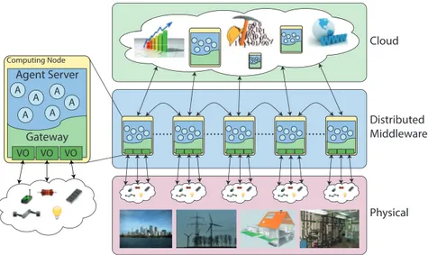
Rainbow architecture is shown in Figure 2.1. As it can be seen, the archi-tecture could be divided into three layers. The bottom layer is the one that is devoted to the physical part. It encloses sensors and actuators, together with their relative computational capabilities, which are directly immersed in the physical environment.
In the Intermediate layer, sensors and actuators of the physical layer are represented as virtual objects (VOs). VOs offer to the agents a transparent and ubiquitous access to the physical part due to a well-established interface exposed as API. VO allows agents to connect directly to devices without care about proprietary drivers or addressing some kind of fine-grained technological
Cloud Physical Distributed Middleware VO VO VO A A A A A A Gateway Agent Server Computing Node
Fig. 2.1. Rainbow architecture.
issues. Each VO comprises “functionalities” directly provided by the physi-cal part. Essentially, a VO exposes an abstract representation (i.e. machine readble-description) of the features and capabilities of physical objects spread in the environment. Functionalities exposed by different types of VOs can be combined in a more sophisticated way on the basis of event-driven rules which affect high-level applications and end-users.
In summary, as detailed in section 2.3.1, all the devices are properly wrapped in VOs which, in turn, are enclosed in distributed gateway contain-ers. The computational nodes that host the gateways represent the middle layer of the Rainbow architecture. Each node also contains an agent server that permits agents to be executed properly. Gateways and agent servers are co-located in the same computing nodes in order to guarantee that agents exploit directly the physical part through VO abstraction. Instead of trans-ferring data to a central processing unit, we actually transfer the process (i.e. fine-grain agent’s execution) toward the data sources. As a consequence, less data needs to be transferred over a long distance (i.e. toward remote hosts) and local access and computation will be fostered in order to achieve good performance and scalability. Furthermore, since agents and Virtual Objects can be dynamically added or removed, if a system is well designed, it can be dynamically reconfigured and extended taking into account new physical objects and desired behaviour.
The upper layer of Rainbow architecture concerns the cloud part. This layer addresses all the activities that cannot be properly executed in the middle layer like, for instance, algorithms needing complete knowledge, tasks that require high computational resources or when a historical data storage is
2.3 Rainbow architecture 29
mandatory. On the contrary, all tasks where real time access to the physical part is required could be suitably executed in the middle layer.
2.3.1 Virtual Objects
We address issues about heterogeneity in CPS by introducing the Virtual Object (VO) concept. VO aims to hide heterogeneity by supplying a well-established interface permitting the physical parts to be suitably integrated with the rest of the system.
VO could be defined as a collection of physical entities like sensors and actuators, together with their computational abilities.
It can be composed of just a simple sensor or it can be a more complex object that includes many sensors, many actuators, computational resources like CPU or memory and so on.
In general, VO outputs can be represented by punctual values (e.g. the temperature at a given point of a room) or aggregate values (e.g. the average of moisture during the last 8 hours). Also, the values returned by VOs could be just the measurement of sensors or could be the result of complex compu-tations (e.g. the temperature of a given point of space computed by means of interpolation of the values given by sensors spread across the environment).
Furthermore, a VO could supply actuation functionality by changing the environment on the basis of external triggers or internal calculus.
These different kinds of behaviour that VO can expose must be taken into account. VO is therefore conceived as a complex object that can read and write upon many simple physical resources. More in detail, we consider that each VO exposes different functionalities. Each functionality can be either sensing or actuating and can be refined by further parameters that dynamically configure it.
The previous assumption leads to the definition of resource as the following triplet :
[V OId, V OF unctionId, P arams]
Where VOId uniquely identifies the VO, VOFunctionId identifies the spe-cific functionality and Params is an ordered set of parameter values that con-figure the functionality.
For example let’s consider a Virtual Room made of sensors for measur-ing different physical quantities inside a room such as temperature, moisture, brightness and so on. Suppose now you want to read from Smart Room the temperature in a given spatial point of the room. In that case the triplet could be:
[V irtualRoom, temperature, [x, y, z]]
Using object oriented terminology, a Resource could be seen as a particular “instance” of a functionality of a given VO.
Besides read and write operations (i.e. sensing and actuation), it is pro-vided for VOs to be able to manage events that occur in the physical part. To that scope, our proposed middleware includes a publish/subscribe component for managing events in each computing node. Each event is defined by a logical rule where one or more VOs could be involved.
Each rule is a logical proposition in which the atomic predicates can be of the following kinds:
- resource < threshold (e.g. temperature < 300) - resource > threshold
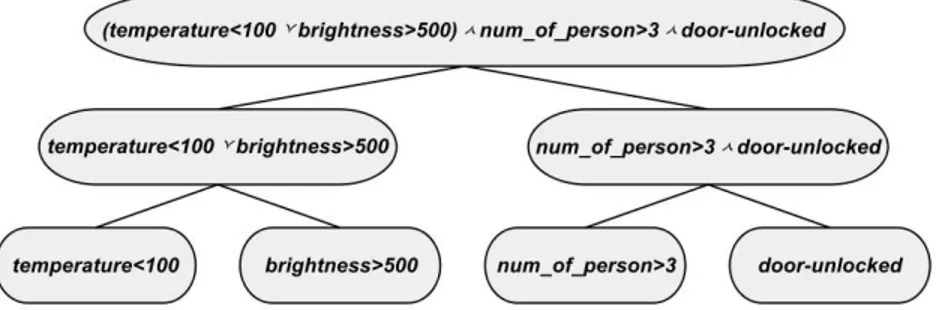
- boolean resource (e.g. the door was unlocked) Just an example of rule:
(temperature < 100 and brightness >500) or people > 3 or door unlocked The publish/subscribe manager component is in charge to parse the logical rule and generate a binary tree made as explained below: each node N of the tree corresponds to a logical proposition N (). given L and R, the child nodes of N , their associated logical propositions are respectively L() and R() so that it results either N() = L() or R() or N() = L() and R(). The radix of the tree corresponds to the entire rule while the leaves contain the atomic propositions that is passed to the suitable VOs. A binary tree representation example of a composed rule is shown in Fig. 2.2.
Fig. 2.2. Example of binary tree of a rule.
A VO is in charge to establish each time when the assigned atomic propo-sitions are true or f alse. The logical proposition of a given node is computed on the basis of the value of its child nodes. The root of the tree is recursively involved by this bottom-up computation. As soon as the value of the root node (i.e. the value of the entire rule) changes all the subscriber will be notified.
2.3 Rainbow architecture 31
All the physical things linked to a computing node together with relative VOs is enclosed in the Gateway container. The Gateway exposes an interface to interact directly with the VOs.
Each gateway represents the “entry point” that agents can use to exploit VOs of the relative computing node.
In the following is described the interface of Gateway that will be used by the overlying layer:
interface GatewayInterface {
void resourceNaming(String name, VOId voId, VOFunctionId functionId , VOFunctionParams params);
VOResult check(String name);
VOResult check(String name, VOFunctionParams params); VOResult acting(String name);
VOResult acting(String name, VOFunctionParams params);
void setRule(Rule rule, String idRule);
void subscribe(String idRule, EventHandler handler); }
The method resourceNaming assigns an identification name to a given resource supplied by a given VO. A resource is a specific instance of a func-tionality of a VO refined by some parameters. In other word, a resource is the above-mentioned triplet: [V OId, V OF unctionId, P arams]. The name as-signed to a resource via resourceNaming can be used in the other methods in order to simply identify the resource. Furthermore, the identification name of a resource is useful to compose the rules in a more human-readable fashion.
The method check reads the current value of the resource identified by name whereas acting triggers the actuation operation upon the resource iden-tified by name. Both check and acting methods are of two kinds: the first take only name as parameter and refers to the resource as it is previously defined in resourceNaming; the second kind, instead, permits the parameters of the referred resource to be refined dynamically.
The method setRule permits a complex rule to be published (e.g. (temper-ature < 100 and brightness >500) or number of person > 3 or door unlocked ) and to assigns an id (i.e. idRule) useful for subscribing the rule afterwards.
The method subscribe permits a previously published rule (identified by idRule) to be subscribed. The occurrence of the event identified by idRule will be notified to the handler passed as a parameter to the method. 2.3.2 Rainbow Multi Agent system
The Multi Agent component of the rainbow architecture is made up of the following entities: Agents, Messages, the Agent Server and the Deployer. Fig-ure 2.3 shows these entities and how they interact among themselves and with the Gateway.
Gateway
Server
Agent
Agent
Deployer
Check Acting Set Rule Subscribe HAND LE_E VENT SE ND _M ESSA GE RE CE IVE_M ESSA GE AD D_ ACQ UAIN TA NCE REM O VE_A CQ UAIN TA NCE ADD_AGENT REMOVE_AGENT Send acquaintance msgsFig. 2.3. Rainbow multi-agent entities.
The Agent Server is the container for the execution of agents. It offers functionalities concerning the life cycle of the agents as well as functionali-ties for agents’ communication. Agent servers are arranged in a peer-to-peer fashion where each agent server hosts a certain number of agents and per-mits them to execute and interact among themselves in a transparent way. In other words, when an agent requests the execution of a functionality, its host agent server is in charge of redirecting transparently the request to the suitable agent server. In the following are listed the main functionalities each agent server exposes:
SEND MSG. Through this functionality, the communication between agents is performed. The Agent Server is responsible for correctly delivering mes-sages from the sender agent to the receiver one. If the sender and the receiver do not belong to the same agent server, the message is forwarded to the suitable “peer” agent server which is, in turn, engaged finally to deliver the message. The latter mechanism is showed in figure 2.4(a). ADD AGENT. It instances an agent to an agent server. Rainbow Multi Agent
system is designed to permit agents to be dynamically loaded to the agent server they have to belong to. As in SEND MSG operation, agent servers are in charge for exchanging information among themselves in or-der to guarantee the ADD AGENT request to be delivered to the correct agent server. This mechanism is shown in figure 2.4(b). The latter figure also shows how the code is dynamically loaded exploiting class repository server. More in detail, when an ADD AGENT request reaches the suitable agent server, if the agent code is not already available, the agent server automatically downloads it from a class repository.
REMOVE AGENT. It removes an instance of an agent hosted by an agent server. This operation also exploits the “forwarding” mechanism described above.
2.3 Rainbow architecture 33 Agent Server 1 Agent Server 0 B Agent Agent Agent Agent Agent Agent SEND_MESSAGE forwarding A SEND_MESSAGE (a) SEND MSG Agent Server 1 Agent Server 0 A Class Repository Agent Agent Agent Agent Agent Agent ADD_AGENT (“A”, “Agent Server 1”)
ADD_AGENT forwarding ADD_AGENT (“A”) send class request class (b) ADD AGENT Fig. 2.4. Forwarding mechanism
A Message is the atomic element of communication between agents. It carries an application specific content together with informations about the sender agent and the receiver one.
Our architecture provides for specific kinds of message, that are the ac-quaintance messages. Those messages are used for establishing an acquain-tance relationship among agents. The acquainacquain-tance message carries informa-tion about the locainforma-tion of a given agent (i.e. locainforma-tion of hosting agent server). The agent who receives the acquaintance message will use this information when it needs to send messages toward that destination. This kind of mech-anism ensures agent behaviour to be completely independent w.r.t. the loca-tions of agents it has to collaborate with.
For instance, let’s consider that an agent is a computing node intercon-nected with others by means of a ring network. Each agent, therefore, can only interact with its previous agent nodes and its next one. Whenever fur-ther nodes must be connected to the ring network, only the acquaintance relationships have to be updated. In other words, a third entity can establish dynamically those acquaintance relationships without resorting to modifying, re-building or restarting any agent.
In rainbow architecture the entity which is in charge of sending acquain-tance messages in order to establish the acquainacquain-tance network is called De-ployer. Deployer could be an external process as well as an agent, it can run during the configuration phase as well as during application execution. The Deployer concept will be described in details in section 2.3.2.
An Agent is an autonomous entity which executes its own behaviour inter-acting with other agents via Agent Server. In addition, each agent can interact
with the physical part exploiting functionalities exposed by the Gateway (i.e. using the Virtual Object abstraction).
The functionalities of an agent are exposed to its own Agent Server and Gateway. As said before, Agent Servers are in charge of the “forwarding” mechanism that eventually ends with the calling of these functionalities, while the Gateway is in charge of notifying the events that occur in the physical part. In the following are listed the main functionalities of an agent:
RECEIVE MESSAGE. It is called when there is a Message to be delivered for the agent.
HANDLE EVENT. It is called by the Gateway to notify that an event is occurred in the physical part.
ADD ACQUAINTANCE. It is called when there is an acquaintance message to be delivered to the agent. The implementation of this functionality concerns the store of the acquaintance relationship between the agent itself and the agent identified inside the message.
REMOVE ACQUAINTANCE. It is called for removing a previously stored acquain-tance relationship.
The specific behaviour of an Agent is realized through the implementation of RECEIVE MESSAGE and HANDLE EVENT functionalities.
Dynamic Deployment and Roles
The deployment of the agents as well as the configuration of the acquaintance relationships and the start-up of the application are all actions performed by the so-called Deployer. An external process or even an agent can act as a Deployer. The deployment phase is typically executed just before the applica-tion can start properly; however, it is possible to act as Deployer even during application execution in order to update the configuration dynamically for hosting new features or adapting to foreseen and unforeseen changes in the environment. Deployer can be implemented centrally or in a distributed way. Basically, who acts as a Deployer operates using the ADD AGENT functionality for deploying a new instance of an agent into an agent server, REMOVE AGENT for removing a running agent from an agent server. Furthermore, Deployer is responsible for sending acquaintance messages that eventually end with calls to ADD ACQUAINTANCE or REMOVE ACQUAINTANCE on the specific agents. Finally, Deployer is also in charge of sending suitable “start” messages using SEND MSG in order to start the application properly.
The acquaintance relationship is formally defined by a triplet: [A, B, R] where A and B are the agents involved in the relationship and R is a Role label. The triplet above means that agent A knows agent B and that B has the role R as acquaintance of A. During the execution, an agent exploits the Roles of its acquaintances to discriminate about how to interact with them.
2.4 Conclusions 35
As an instance, let’s consider that each agent represents a physical person in a town. The relationship between two agents could have roles of neigh-bourhood and/or friendship. A deployer is in charge of configuring those re-lationships during the initial phase. In addition, as soon as a person changes home or starts a new friendship, the deployer has to re-arrange relationships dynamically among agents through sending acquaintance messages. During the execution of that system, each agent will use roles of neighbourhood and friendship to discriminate how to interact with other agents. For instance he/it can exchange information about its district with its neighbours while it invites its friends to a party.
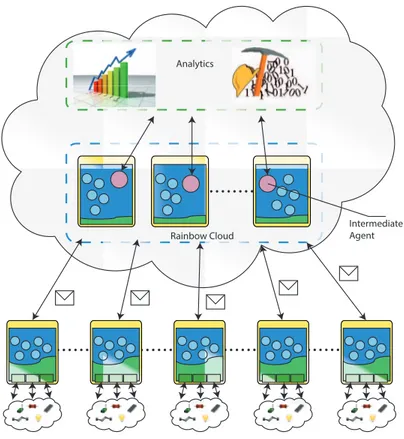
2.3.3 Cloud layer
In the cloud part a set of Rainbow nodes are deployed and run on a cloud in-frastructure. Such nodes lack of the Virtual Objects Gateway since, obviously, there are no physical entities connected. For this reason each node consists of the only agent server. The communication between the nodes connected with the physical part and the nodes in the cloud occurs by means of message exchange (see Section 2.3.2).
Agents located on the cloud nodes act as intermediary between the Rain-bow MAS and cloud analytics services. The feature of adding new agents at runtime can be used to link new services in the cloud during the execution of the system (no reboot is needed).
The Rainbow cloud part is PaaS, namely it provides a software stack and a set of libraries for the application execution. Anyway, it also can be seen as SaaS because the Rainbow user, i.e. the application developer, can inject his application by remotely add the needed agents.
2.4 Conclusions
In this chapter we introduced Rainbow, an architecture that permits an easy development of large-scale cyber-physical applications. The novelty of Rain-bow is that it relies on the adoption of a distributed multi-agent layer on top of the physical part that is, in turn, wrapped in suitable Virtual Objects. Rainbow aims to hide heterogeneity, cope with complexity and real-time is-sues. In the future, new intelligent, adaptive and decentralized algorithms will be explored for developing large-scale cyber-physical applications using Rain-bow, such as those related to smart cities, power grid, water networks and so on.
In the following chapters a set of application scenarios that use Rain-bow will be presented. Chapter 3 shows applications and solution for Smart Buildings, Ambient Assisted Living and Smart Cities scenarios. Chapter 4 is entirely focus on a CPS for an urban drainage systems, which implements a
Intermediate Agent Rainbow Cloud
Analytics
Fig. 2.5. Rainbow cloud layer.
novel decentralized approach so as to obtain a behaviour which is effective in reducing environmental impact of the drainage network.
3
Rainbow in action
3.1 Introduction
In this chapter we details the design of four CPS which exploit the features and capabilities provided by the Rainbow framework in different application scenarios.
The first one (Section 3.2) is a case study which aims to show our archi-tecture from a practical perspective so as to better understand and figure out all the system’s details and concerns a Building Automation scenario..
The second scenario (Section 3.3) concerns the use of the platform for mapping the noise pollution on an urban area, and shows how Rainbow can be exploited to run swarm intelligence algorithms in order to realize CPS applications owning properties such as adaptivity, fault tolerance, self-reconfiguration.
The third scenario (Section 3.4) proposes a solution for Ambient Assisted Living in Smart Home environment. The main purpose of this section is to point out how a knowledge discovery workflow can be realized involving all the three layers of the proposed architecture1.
The last scenario (Section 3.5) is about the design of a Smart Street en-vironment. Indeed, this scenario has been physically realized in the city of Cosenza (Italy).
3.2 Floor control
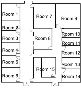
This section presents an application for monitoring and controlling a floor of a building hosting offices. Each floor contains a certain number of room.
1 G. Fortino, A. Giordano, A. Guerrieri, G. Spezzano, A. Vinci. A Data
Analyt-ics Schema for Activity Recognition in Smart Home Environments. Proceedings of9th International Conference on Ubiquitous Computing and Ambient Intelli-gence (UCAMI 2015) (to appear)
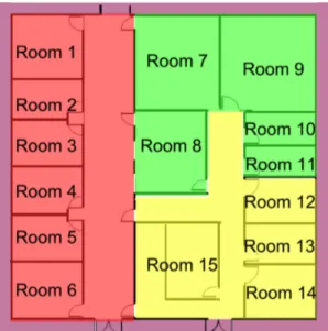
Fig. 3.1. Floor topology.
Figure 3.1 shows how a generic floor could be. In general, each room con-tains: doors, desks, chairs and adjustable brightness lights.
Each room is instrumented by some sensors and actuators listed below. Sensors:
• sensors that detect the opening and closing of doors; • sensors that detect when a person enters or leaves a room;
• proximity sensors detecting presence of the people in each zone of a room; • a weight sensor for each chair in order to detect if the chair is currently
used. Actuators:
• adjustable brightness lights for all zones of a room; • a display on each desk.
The use of the above described devices, for example, permits adjusting lights on the basis of people movements, writing informational messages on displays and so on.
Integration in Rainbow using Virtual Objects
In order to develop the controlling part in a object-oriented fashion, it is required to integrate the above described physical things with Rainbow mid-dleware defining the suitable Virtual Object(VO). Each VO abstracts and
3.2 Floor control 39
wraps a certain number of sensors as well as actuators. For the sake of sim-plicity, in this example we chose to design VOs in a human-readable fashion: virtual desk, virtual chair, virtual door and virtual wall.
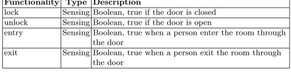
The functionalities exposed by these VOs are listed in table 3.1, 3.2, 3.3, 3.4. It is worth to note that each functionality of the virtual wall is parametric: the zone parameter specifies which area of the room is referred.
Functionality Type Description
lock Sensing Boolean, true if the door is closed unlock Sensing Boolean, true if the door is open
entry Sensing Boolean, true when a person enter the room through the door
exit Sensing Boolean, true when a person exit the room through the door
Table 3.1. Virtual Door.
Functionality Type Description
proximity Sensing detects people near the chair
sitting Sensing Boolean: true when someone sits on the chair Table 3.2. Virtual Chair.
Functionality Type Description
near people Sensing number of people in the zone (supplied by parameter) add light Acting increase light brightness in the zone (supplied by
parameter)
less light Acting decrease light brightness in the zone (supplied by parameter)
light off Acting set off light in the zone (supplied by parameter) Table 3.3. Virtual Wall.
Functionality Type Description
proximity Sensing detects people near the desk
display Acting show a message supplied by parameter on the display Table 3.4. Virtual Desk.
Each VO is located on the same computing node where the sensors and actuators that VO encloses are connected to. A computational node can gen-erally host VOs that may refer to more than one room. Assuming than we have only three computational nodes available to monitor and control the whole floor, we can assign rooms to nodes as in figure 3.2.
Fig. 3.2. Rooms assignment to computational nodes. Each different color identify a different node.
Multi-agent floor application
The application is designed for managing the floor and its rooms. For each room a energy-saving light-management is developed which considers people presence for suitably adjusting the brightness of the various zones of a room. This control management will also consider if the chairs are utilized or not in order to better adjust the lights. In addition, it permits a message to be displayed on a certain desk when needed. All those features are implemented in the RoomAgent. The code inside the RoomAgent is a typical object-oriented code where VOs are exploited as simple objects. The code is omitted in this chapter for sake of brevity.
Besides this room-wise features, the application is also designed for ad-dressing issues concerning the entire floor (i.e. where more than one room is involved). For instance, it could be useful to know how many people are in the floor at a given time in order to properly manage the locking of the main
3.2 Floor control 41
door of the floor as well as to shut down all the lights where the floor is empty. In this example, instead, the knowledge of the number of people is used to notify a person when he is alone in the floor writing a message on the display of his desk.
The FloorAgent is designed for addressing the above mentioned issues. Summarizing, there is a RoomAgent per room and a unique FloorAgent as it is shown in figure 3.3. RA1 RA2 RA3 RA4 RA5 RA6 RA7 RA8 RA9 RA10 RA11 RA12 RA13 RA15 RA14 FA
Fig. 3.3. Logical distribution of agents in the floor.
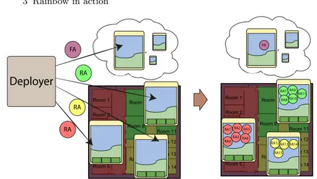
Deployment of the application
As mentioned before the Deployer is in charge to load the agents upon the agent servers, to establish acquaintance relationships among them and to start the application.
In our application, each RoomAgent must be located in the computing node where the VOs of the relative room belong to.
Conversely, the FloorAgent can be located everywhere in the system (it has not connection with any physical part), even in a remote cloud node. The process made by the Deployer is summarized in figure 3.4.
Agent interaction and acquaintance relationships
After loading each agent in the proper location, the Deployer sends acquain-tance messages to each RoomAgent in order to let them know the FloorAgent.