Integrai Circulation Experiment:
Thermal-Hydraulic Simulator of a LFR Primary System
Descrittori
Tipologia del documento:
Collocazione contrattuale: Accordo di programma ENEA-MSE: tema di ricerca "Nuovo nucleare da fissione"
Argomenti trattati:
Sommario
In the frame of the Programmatic Agreement (AdP) between the Italian Ministry of the Economie Development (MSE) and ENEA, the Experimental Engineering Technical Unit (UTIS) of Brasimone is strongly involved in the domain LP3 focused on the Generation IV Innovative Reactor. This domain foresees, in synergy with the domain DEMETRA in the frame of IP-EUROTRANS, a large-scale tests to characterise a relevant portion of a LFR/ADS reactor block (core, internals, heat exchanger) and qualify a prototypical decay heat removal (DHR) heat exchanger, both in steady state than in transient and accidental conditions.
To achieve the goals above mentioned, an integrai circulation experiment (ICE) aiming to reproduce the primary flow path of a LFR/ADS pool-type nuclear reactor has been designed and implemented, and an appropriate test section has been designed to be installed in the CIRCE facility.
The paper reports a description of the experiment, the designed test section and an overview of the its main components (Heat Source, Heat Exchanger) as well as the experimental activities carried out in support to design of the ICE by the NACIE loop facility.
Finally, the preliminary experimental results carried out in the first experimental campaign run on the CIRCE pool are reported.
Note: Attività LP3-B Copia n. In carico a: 2 NOME FIRMA 1 NOME FIRMA
o
EMISSIONESUMMARY
1. Introduction 3
2. The Integral Circulation Experiment 4
2.1 Aim of the Experiment 4
2.2 CIRCE FACILITY 4
2.3 ICE TEST SECTION 5
2.4 Heat Source 6
2.5 Prototypical Heat Exchanger 9
3. Experimental Support for Heat Section Design 11
3.1 NACIE Loop 11
3.2 Performed Test 12
3.3 Natural Circulation Test 13
3.4 Gas Enhanced Circulation Test 13
4. ICE Activity: First Experimental Results 19
5. Conlusions 27
1. INTRODUCTION
Since 1999 the ENEA Brasimone Research Centre is strongly involved in the frame of the heavy liquid metal technology development.
It started to investigate technological problems related to the operation of Lead and Lead Bismuth Eutectic in Accelerator Driven Systems (ADS) and/or Lead cooled Fast Reactors (LFR) in the frame of the national programs funded by the Italian Minister for University and Scientific and Technological Research (MURST).
During these last years, by the Brasimone Research Centre large competencies and capabilities in the frame of the nuclear energy systems have been developed, in particular in the field of material for high temperature applications, corrosion and material protection (in liquid metal, gas, water), heat transfer and removal, component development and testing, remote maintenance, procedure definition and non-conventional coolant handling.
Large and innovative experimental facilities, as well as laboratories for materials testing and diagnostic, have been built up increasing the capabilities of the research centre in these fields.
These wide competencies and relevant infrastructures allowed to take part to main European research programme funded in the frame of the Framework Programme (FP).
In the frame of these European activities important R&D programmes have been dedicated worldwide to the Generation IV LFR and ADS concept development, like for example the ELSY project “European Lead-Cooled System”, aimed at showing the possibility of realization and operation of a safe and competitive fast lead-cooled critical reactor.
Wide importance is given also to the activities in support of the development of systems for the transmutation of radioactive waste, as can be noticed from the Integrated Project EUROTRANS “EUROpean research programme for the TRANSmutation of high level nuclear waste in Accelerator Driven Systems”, which concurs to demonstrate the feasibility of an ADS-type dedicated transmuter.
The main objective of EUROTRANS is, in fact, to carry out a first advanced design of experimental facility demonstrating the technical feasibility of Transmutation in an Accelerator Driven System (XT-ADS), as well as to accomplish a generic conceptual design of the European Facility for Industrial Transmutation EFIT (realisation in the long-term).
This step-wise approach is termed as European Transmutation Demonstration (ETD) approach.
In particular, in the frame of EUROTRANS, the Domain DEMETRA “Development and assessment of structural materials and heavy liquid Metal technologies for Transmutation systems” is focused on the HLM technologies and materials.
ENEA, as leader of the “Integral Test Experiment” task, assumed the commitment to perform an integral experiment with the aim to reproduce the thermal hydraulic behaviour of a relevant part of the primary system of a heavy liquid metal cooled nuclear reactor in a pool configuration.
In synergy with the R&D programmes funded in the frame of the European FPs, the Italian Ministry of the Economic Development (MSE) funded a dedicated research and development activities aiming to support the development of the LFRs.
In particular, in the frame of the Programmatic Agreement (AdP) between MSE and ENEA, the Experimental Engineering Technical Unit (UTIS) of Brasimone assumed the commitment to perform large-scale tests aiming to characterise and qualify a prototypical decay heat removal (DHR) heat exchanger, proposed for the ELSY LFR-concept.
To achieve the synergic goals above mentioned, an integral circulation experiment (ICE) aiming to reproduce the primary flow path of a heavy liquid metal (HLM) pool-type nuclear reactor has been designed and implemented, and an appropriate test section has been designed to be installed in the CIRCE facility [1].
The ICE activity, when accomplished, will strongly contribute to the demonstration of the LFR/ADS pool-type nuclear reactor feasibility.
The design and implementation of the ICE activity required the development of a support facility, named NACIE (Natural Circulation Experiment) [2] built up to carry out experimental tests needed to address the phenomena related to the natural and gas enhanced circulation flow regimes, and to test and qualify components for heavy liquid metal cooled systems.
2. THE INTEGRAL CIRCULATION EXPERIMENT
2.1AIM OF THE EXPERIMENT
In the frame of the domain DEMETRA and AdP-LP3, large-scale tests to characterise a relevant portion of a LFR/ADS reactor block (core, internals, prototypical heat exchanger, structural material) in steady state, transient and accidental conditions were scheduled.
For this aim, ENEA designed and implemented the ICE activity, with the objective to obtain information about different topics such as:
the thermal-hydraulics behavior of a HLM pool system by the analysis of the coupling between an appropriate heat source and a cold sink placed inside;
characterization of representative components (i.e. prototypal DHR-heat exchangers) for the LFR concepts;
operational and accidental transients;
transition from the forced to the natural circulation flow regime, qualification of a chemistry control system for HLM pool
Moreover the ICE activity will allow to establish a reference experiment for the benchmark of commercial codes when employed in HLM pool systems.
2.2CIRCEFACILITY
The ICE activity has been designed to be implemented on the CIRCE facility. CIRCE basically consists of a main cylindrical vessel (S100) with an outer diameter
different test sections welded to and hung from bolted vessel heads for the study of the thermal-hydraulic issues related to the HLM pool systems. The main vessel is moreover equipped with auxiliary systems for eutectic circulation, with argon cover gas and recirculation system, LBE heating and cooling systems.
The facility is complete of a LBE storage tank (S200), of a small LBE transfer tank (S300) and of the data acquisition system. In figure 1, an isometric view of the facility is shown. The main parameters relevant to the test vessel are listed in figure 1.
2.3ICETESTSECTION
The ICE test section was designed to reproduce, as close as possible, the thermal-hydraulic behaviour of the XT-ADS and EFIT primary systems [3,4,5,6,7] .The main experimental parameters characterizing the ICE experiments are reported in table 1, where they are compared to the values characterising XT-ADS and EFIT.
As can be noted, the main ICE experimental parameters are roughly in the range expected for the XT-ADS and EFIT concepts. The main difference between ICE and XT-ADS/EFIT concepts is the P/D ratio value. In fact, for the ICE test section a P/D ratio value of 1.8 is adopted to reduce the overall pressure drop along the primary flow path, still preserving the main characteristics of the heat source and allowing performing the tests with the available pumping system (gas-lift technique).
Parameters Value
Outside Diameter 1200 mm Wall Thickness 15 mm
Material AISI 316L
Max LBE Inventory 90000 kg Electrical Heating 47 kW Cooling Air Flow Rate 3 Nm3/s Temperature Range 200 to 550 °C Operating Pressure 15 kPa (gauge) Design Pressure 450 kPa (gauge) Argon Flow Rate 15 Nl/s
Argon Injection Pressure 600 kPa (gauge)
XT-ADS EFIT ICE
Coolant LBE Pure Lead LBE
Primary Loop Circulation Mechanical Pump
Mechanical Pump
Gas Lift Technique Fuel Assembly Lattice Hexagonal Hexagonal Hexagonal
Fuel Assembly Type Wrapper Wrapper Wrapper
Fuel Assembly Spacer Grid Grid Grid
Fuel Pin Diameter (D) [mm] 6.55 8.72 8.2
Pitch to Diameter Ratio (P/D) 1.41 1.56 1.8
Fuel Heat Flux q’’ [W/cm2] 85-115 100-140 100
Fuel Power Density q’’’ [W/cm3] 500-700 450-650 488 Average Velocity Fuel Pin Region [m/s] 1 1 1
Fuel Pin Active Length [mm] 600 900 1000
Tin/Tout core [°C] * 300/400 400/480 300/400
THS/Lact [°C/m] 167 88 100
Fuel Pin Cladding Material T91 T91 AISI 316L Secondary Coolant Low Pressure
Boiling Water Water with superheated steam Low pressure boiling water
*This value refers to the thermal difference between the inlet and outlet section of the ICE Heat Section (made by a single bundle); for EFIT and XT-ADS it refers to the thermal difference between the upper plenum and lower plenum of the core.
Table 1. Overview of the experimental parameters adopted for the ICE activity
2.4HEAT SOURCE
The Heat Source is coupled with the test section by an appropriate mechanical structure. The HS and the mechanical structure which surrounds it make up the so called Fuel Pin Simulator, FPS.
The ICE heat source consists of a pin bundle made by electrical heaters with a nominal thermal power of 800 kW (total power of 925 kW); it has been designed to achieve a difference temperature through the HS of 100 °C, a fuel power density of 500 W/cm3 and an average liquid metal velocity of 1 m/s, in accordance with the reference values adopted for the LFR/ETD concepts.
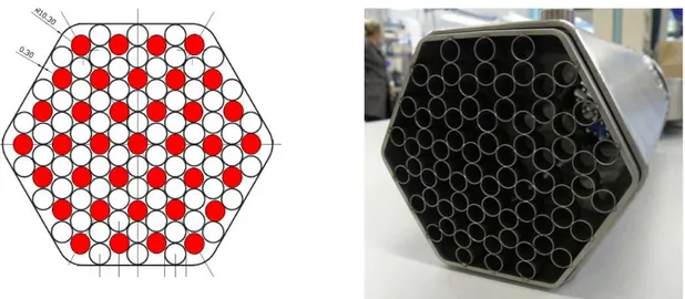
The ICE heat source consists of 37 pins placed in a wrapped hexagonal lattice with a pitch to diameter ratio of 1.8 (see figure 3). Each pin has an outer diameter of 8.2 mm, a power of about 25 kW and a wall heat flux of 1 MW/m2; the selected active length is 1000 mm and the adopted cladding material is AISI 316L. To get an average LBE velocity of 1 m/s, a flow rate of 55.2 kg/s is needed through the HS.
Along the HS, three spacer grids (see figure 3) are placed aiming to assure the relative position of the pins inside the bundle, improve the mixing of the coolant and guarantee a uniform and constant sub-channel cross section during the tests.
Heat Exchanger Cover Head Riser Dead Volume Fitting Volume Flow Meter Feeding Conduit Insulation Volume
CIRCE main vessel (S100) Coupling Flange FPS Heat Exchanger Cover Head Riser Dead Volume Fitting Volume Flow Meter Feeding Conduit Insulation Volume
CIRCE main vessel (S100)
Coupling Flange
FPS
Heat Exchanger
Feeding Conduit Separator
CIRCE main vessel (S100) Riser Dead Volume Fitting Volume FPS Flow Meter Heat Exchanger Feeding Conduit Separator
CIRCE main vessel (S100) Riser Dead Volume Fitting Volume FPS Flow Meter
As already mentioned, the main difference between the ICE Heat Source and ETD fuel assembly concepts is the P/D ratio value. In fact, a so high P/D value has been adopted to reduce the overall pressure drop along the primary flow path, preserving the high thermal performance of the heat source. Due to the available pumping system in the CIRCE facility, namely the gas lift pumping system, in order to carry on the ICE activity it was necessary to decrease as much as possible the pressure drop along the heat source, which amount to about the 70-80% of the overall pressure drop.
The gas lift technique [9] was successfully tested and qualified during the previous experimental campaigns performed in CIRCE [10, 11] and a pressure head of 40 kPa is available to promote the LBE circulation along the flow path.
The reference reactor fuel rods will be simulated by prototypical electrical pins constituting the heat source. Before to run the ICE activities the prototypical pins needed to be tested and qualified by a dedicated experimental campaign. The qualification tests were performed on the NACIE loop.
Figure 3 .Cross Section of the ICE Heat Source, and view of the spacer grid
2.5PROTOTYPICAL HEAT EXCHANGER
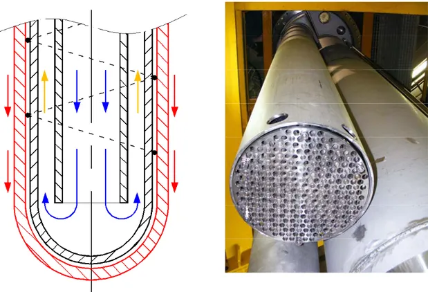
For the ICE activity the cold sink consist of a cooling water circuit, a LBE-low pressure boiling water shell heat exchanger, interconnecting piping, and steam vent piping to discharge steam into the atmosphere.
In particular, the HX is made of bayonet tubes. The bayonet consists of three concentric tubes (see figure 4), the outer two of which have the bottom end sealed. The water flow downward in the inner pipes, and then upward in the annulus between the inner and intermediate pipes. In the annulus vaporization takes place. The annulus between the middle and outer pipes is filled by pressurized helium (4.5 bar). All annuli are interconnected to form a common gas plenum, the pressure of which is continuously monitored. A leakage from either walls of any of the outer tubes is promptly detected because of depressurization of the common helium gas plenum. The two outer tubes are mechanically and thermically decoupled. This configuration
allows to localize the most part of the thermal gradient, between lead and boiling water across the gas layer, avoiding both risk of lead freezing and excessive thermal stresses across the tube walls during steady state operation and transients.
3. EXPERIMENTAL SUPPORT FOR HEAT SECTION DESIGN 3.1NACIELOOP
In the frame of the R&D activities ongoing by ENEA for the LFR/ADS development, by the Brasimone research centre a LBE loop has been built up in 2008, named NACIE [2, 12]. The aim of NACIE loop (see figure 5) is to set up a support facility able to qualify and characterize components, systems and procedures relevant for HLM nuclear technologies. Moreover, by this facility it will be possible to perform several experimental campaigns in the field of the thermal-hydraulics, fluid-dynamics, chemistry control, corrosion protection and heat transfer, allowing to obtain correlations essential for the design of the nuclear power plant cooled by heavy liquid metal.
Finally, the possibility to test prototypical pin simulators as well as all their ancillary systems and mechanical connections it has been mandatory in order to confirm the design of the ICE test section. For this reason the NACIE loop was prepared to house a bundle made with prototypical pin simulators in full scale to the ones which will be manufactured for the ICE test section.
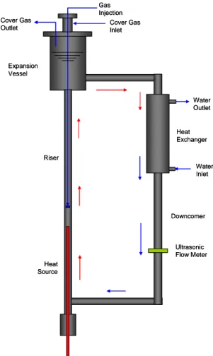
Figure 5-A : NACIE loop layout
Cover Gas Inlet Cover Gas Outlet Gas Injection Heat Exchanger Water Outlet Water Inlet Ultrasonic Flow Meter Heat Source Expansion Vessel Riser Downcomer Cover Gas Inlet Cover Gas Outlet Gas Injection Heat Exchanger Water Outlet Water Inlet Ultrasonic Flow Meter Heat Source Expansion Vessel Riser Downcomer
Figure 5-B :View of the NACIE loop facility
NACIE is a HLM rectangular loop which basically consists of two vertical pipes (O.D. 2,5”) working as riser and downcomer, connected by means of two horizontal branches (O.D. 2,5”).The adopted material is stainless steel (AISI 304) and the total inventory of LBE is about 1000 kg; the design temperature and pressure are 550 °C and 10 bar respectively. In the bottom part of the riser a heat source is installed through an appropriate flange, while the upper part of the downcomer is connected to an heat exchanger. The difference in level between the thermal centre of the heat source and the one of the heat sink was fixed to reproduce the same height that characterises the ICE test section (H = 4.5 m).
The loop is completed by an expansion vessel, installed on the top part of the loop, coaxially to the riser.
3.2PERFORMED TEST
The experimental activity performed on the NACIE facility to support the design of the ICE heat source included several tests concerning natural and gas enhanced circulation. In particular, each test was performed with only one pin activated inside
The NACIE bundle consists of two high thermal performance electrical pins and two dummy pins to support the bundle itself. In the middle section of the active length an appropriate spacer grid is installed, designed to be similar as close as possible to the one adopted for the ICE bundle. Along each pin seven thermocouple have been installed, in order to monitor the trend of the cladding temperature during the test in different position. Appropriate thermocouples have been also installed in order to make a roughly evaluation of the hot spot factor on the pin due to the spacer grid installation.
3.3NATURAL CIRCULATION TEST
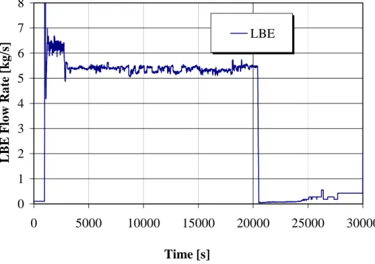
In figure 6 the trend of the HLM flow rate carried out for a natural circulation test is reported. The tests were performed by supplying electrical power to the heater under qualification and circulating coolant in the secondary side of the heat exchanger. During the tests, no gas is injected in the riser, so, the only driving force for fluid circulation in the loop results from thermal buoyancy. After about 2000 seconds a steady state condition is obtained with an estimated flow rate of about 5.5 kg/s.
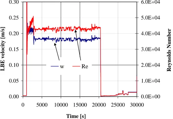
In figure 7 the trend of the inlet and outlet temperature through the heating section is reported, depicting the transients during the natural circulation tests. For the same test, figure 8 reports the value of the Reynolds number and average lead-bismuth velocity through the HS. The cladding temperature trend of the active pin on the matching surface between pin and spacer grid is depicted in the figure 9. Nevertheless the performed test is really severe the temperature is close 500°C. The hot spot factor clearly appear in this figure, being the temperature below the spacer grid higher of about 25°C than the upstream temperature.
3.4GAS ENHANCED CIRCULATION TEST
For what concern the gas enhanced circulation tests, the figure 10 reports the HLM flow rate trend compared with the gas injection flow rate, which promote the LBE circulation along the loop.
Gas enhanced circulation tests were performed by supplying electrical power to the heater starting the argon injection and circulating coolant in the secondary side of the heat exchanger. During the tests, because argon is injected in the riser, the driving force for fluid circulation in the loop results from void buoyancy in the riser.
As reported in figure 10, for the gas enhanced circulation tests the LBE flow rate obtained is higher than the one obtained under natural circulation. With a gas injection of about 5 Nl/min, the liquid metal flow rate falls around 13 kg/s.
In figure 11 the trend of the inlet and outlet temperature through the heating section is reported, depicting the transients during the gas enhanced circulation tests, and highlighting that also in this case a steady state condition is obtained after about 2,000 seconds
For the same test, figure 12 reports the value of the Reynolds number and average liquid metal velocity through the HS; as can be noted the LBE velocity reaches a value of 0.45 m/s, against the 0.18 m/s obtained during the natural
circulation tests, and a Reynolds number of about 100,000, underlining the higher turbulent behaviour of the main stream line in the case of void buoyancy promoted flow. 0 1 2 3 4 5 6 7 8 0 5000 10000 15000 20000 25000 30000 Time [s] LBE Flow R a te [kg/ s] LBE
Figure 6. Heavy Liquid Metal flow rate (NC)
220 240 260 280 300 320 340 360 380 0 5000 10000 15000 20000 25000 30000 Time [s] Tem p era ture [°C] Tin Tout
0.00 0.05 0.10 0.15 0.20 0.25 0.30 0 5000 10000 15000 20000 25000 30000 Time [s] LBE v el o ci ty [ m /s ] 0.0E+00 1.0E+04 2.0E+04 3.0E+04 4.0E+04 5.0E+04 6.0E+04 Reynold s Number w Re
Figure 8. LBE velocity and Reynolds number through the HS (NC)
200 250 300 350 400 450 500 550 0 5000 10000 15000 20000 25000 30000 Time [sec] Temperature [°C ]
Upstream Spacer Grid
Dowstream Spacer Grid Spacer Grid
Figure 9. Cladding temperature trend upstream and downstream the spacer grid. (NC)
0 5 10 15 20 25 30 0 5000 10000 15000 20000 25000 30000 Time [s] LBE F lo w R a te [kg /s ] 0 5 10 15 20 25 30 G a s Flo w Rate [Nl/min] LBE Gas
Figure 10 HLM flow rate and gas injection flow rate (GEC)
260 280 300 320 340 360 0 5000 10000 15000 20000 25000 30000 35000 Time [s] Tem p era ture [°C] Tin Tout
0.0 0.1 0.2 0.3 0.4 0.5 0.6 0.7 0 5000 10000 15000 20000 25000 30000 Time [s] LBE vel o ci ty [m/s ] 0.0E+00 2.0E+04 4.0E+04 6.0E+04 8.0E+04 1.0E+05 1.2E+05 1.4E+05 Re ynolds Numbe r w Re
Figure 12 LBE velocity and Reynolds number through the HS (GEC)
200 250 300 350 400 450 500 0 5000 10000 15000 20000 25000 30000 Time [sec] Temp erature [°C]
Upstream Spacer Grid
Spacer G id
Dowstream Spacer Grid
Figure 13 Cladding temperature trend upstream and downstream the spacer grid. (GEC)
For the gas lift tests, the maximum temperature on the pin is close to 450°C, highlighting that the heat transfer coefficient between the liquid metal and the pin is really increased if compared with the natural circulation tests.
In the figure 13 is depicted the cladding temperature trend upstream and downstream the spacer grid, compared with the trend obtained on the matching surface. Also for this test the hot spot factor clearly appear, and also in this case the temperature below the spacer grid is higher of about 25°C than the upstream temperature.
So, for the experimental test carried out on the NACIE loop, the magnitude of the hot spot factor seems quite independent from the turbulence and liquid metal velocity, at least in the investigated range.
4. ICE ACTIVITY: FIRST EXPERIMENTAL RESULTS
The first and preliminary experimental test performed on the CIRCE facility in the ICE configuration was a steady state full power gas enhanced circulation test.
The test started by the gas injection through the nozzle installed into the bottom of the riser, with an average flow rate of 1.7 Nl/s.
After that a steady state flow rate has been obtained along the primary flow path, the power into the heat source is linearly increased up to 800 kW in 300 s.
When the full power is reached, the heat exchanger is started supplying the cooling water into the manifold.
In figure 14 the trend of the argon flow rate injected into the riser, as well as the promoted primary flow rate through the heat source, is reported. As it can be noted, after about 100 sec from the onset of the gas injection, a liquid metal steady state flow rate of 60 kg/s is obtained, as foreseen in the test specifications.
In the figure 15 the trend of the supplied electrical power to the heat source is reported. As it can be noted, the supplied power is compared with the thermal power extracted by the heat source and the heat exchanger, showing a good agreement among them. Both the HS and HX removed power are calculated by a thermal balance on the LBE stream lines through the inlet and outlet section of the correspondingly components.
During the test, because argon is injected in the riser, the main driving force for fluid circulation in the pool results from void buoyancy in the riser. The driving force available during the test can be estimated measuring the pressure difference through the inlet and outlet section of the riser.
In fact, under the static conditions, the pressure difference along the riser is due to the gravimetric head. During the test, when the circulation is promoted, the pressure difference along the riser is due to three contributes: gravimetric (calculated taking in account the average density of the argon-LBE mixture), acceleration and friction.
Because it has been evaluated that the acceleration and friction contributes are neglected if compared with the gravimetric one [11,13], the measurement of the pressure difference through the riser when the circulation is promoted, allow to make an estimation of the average density into the riser and so an estimation of the average void fraction into the riser. This method is usually defined as manometric method.
In figure 16 the trend of the pressure difference along the riser is depicted. As shown, by the gas injection the gravimetric head into the riser is reduced from 3700 mbar (static head) to 3400 mbar (dynamic head).
Applying the manometric method above described, the average void fraction into the riser during the test is estimated to be about the 4%.
As consequence, it is possible to estimate the driving force available for the LBE circulation [11,13]. The results carried out is depicted in the figure 17, where the pressure head available for the LBE circulation is shown. The estimation takes in account not only the void buoyancy into the riser but also the thermal buoyancy into the heat section evaluated by the Boussinesq approximation [11,13,14].
Figure 14. Trend of the gas injection flow rate and the related LBE flow rate along the ICE test section
Figure 15. Trend of supplied electrical power and the removed thermal power calculated along the heat source and heat exchanger
0 200 400 600 800 1000 1200 0 2000 4000 6000 8000 Time [s] Po w er [ k W ] Eletrical Power Heat Section Heat Exchanger 0 10 20 30 40 50 60 70 80 0 2000 4000 6000 8000 Time [s] F low R a te [ k g/ s] 0.0 0.5 1.0 1.5 2.0 2.5 3.0 3.5 4.0 G a s I n ject io n F low R a te [ N l/ s] LBE Argon
2400 2600 2800 3000 3200 3400 3600 3800 4000 4200 0 2000 4000 6000 8000 Time [s] P res su re [mba r] 0 2 4 6 8 10 12 14 16 18 Void F rac tion DP Riser Void Fraction
Figure 16. Pressure difference measured along the riser during the test and estimated average void fraction into the riser
As it can be noted, the driving force available is about 150 mbar, in good agreement with the value estimated by design.
In the figure 18, the measured thermal difference through the heat section and heat exchanger (LBE side) is reported. As shown the difference falls around 100°C as foreseen by design.
At the inlet of the HS three thermocouples have been installed (TE001, TE002, TE003), placed at different depth into the rod bundle.
As depicted in the figure 19, the temperature profile in the inlet section is really uniform.
The same it has been made at the outlet of the HS, installing three thermocouples (TE004, TE005, TE006) at different depth into the bundle. As shown in figure 19 at the outlet section the temperature fields is not so uniform, highlighting that a certain thermal gradient exist among the involved subchannels of the pin bundle.
Finally figure 19 underlines as the average temperature of the LBE during the full power test falls around 350°C, as required.
The average inlet and outlet temperature trends along the heating section, as well as the inlet and outlet temperature trends through the heat exchanger are shown in the figure 20. As can be noted between the Tout HS and Tin HX a certain difference exists (around 30°C), highlighting a thermal coupling between the fitting volume, riser and the downcomer. The LBE flowing into the fitting volume and then in the riser losses thermal power towards the upper part of the downcomer where the HX is placed.
0 50 100 150 200 250 300 350 400 0 2000 4000 6000 8000 Time [s] P res su re [mba r] Driving Force
Figure 17. Driving force available for the LBE circulation along the ICE flow path
0 20 40 60 80 100 120 140 0 2000 4000 6000 8000 Time [s] Δ T [ °C ] Heat Section Heat Exchanger
Figure 18. Thermal Difference through the inlet and outlet section of the Heat Section and Heat Exchanger (LBE side).
Figure 19. Trend of the temperatures at the inlet (TE001, TE002, TE003) and outlet (TE004, TE005, TE006) of HS. The thermocouples have been installed, both in the inlet than in the outlet, at different depth into the pins bundle, to verify the uniformity of the temperature in the sections.
The same happens for what concern the Tout HX and Tin HS, underlines that the LBE flowing down from the HX is heated into the downcomer before to flow inside the heating section. A thermal coupling exists between the lower part of the downcomer and the test section.
For what concern the liquid metal velocity, one of the main specifications of the experiment was to have an average velocity through the HS of about 1 m/s, as foreseen for the XT-ADS and EFIT concepts. The results carried out shown as also this commitment has been accomplished during the test, as depicted in figure 21. In the same figure the Reynolds number of the LBE stream line inside the rods bundle is reported, equal to 1.1E+5, underlines as the flow is highly turbulent, fully developed.
Again, in the figure 21 the LBE average velocity though the bayonets tubes of the Heat Exchanger is reported. As it can be noted, there the LBE velocity 80% lower than in the rods bundle (0.12 m/s). As consequence also the LBE stream line turbulence is lower, even if the flow remain turbulent being Reynolds equal to 1.8 E+4.
For what concern the water side of the prototypical heat exchanger, as can be noted from the figure 22, for the run of the full power test a water flow rate of 0.57 kg/s has been supplied. The measured pressure loss through the heat exchanger was 1.5 bar. 250 300 350 400 450 0 2000 4000 6000 8000 Time [s] Te m p er at u re [ °C]
TE001 TE002 TE003 TE004 TE005 TE006
Figure 20. Trend of the average inlet and outlet temperature along the HS and inlet and outlet temperature through the HX (LBE side).
0.0 0.2 0.4 0.6 0.8 1.0 1.2 1.4 0 2000 4000 6000 8000 Time [s] V el o ci ty [m/s ] 0.0E+00 2.0E+04 4.0E+04 6.0E+04 8.0E+04 1.0E+05 1.2E+05 1.4E+05 Reynold s Numbe r Velocity (HS) Velocity (HX) Re (HS) Re (HX)
Figure 21. Average LBE velocity through the rods bundle and bayonet tubes of the HX. Reynolds number for the liquid metal stream line inside the HS and HX. Full
power test . 250 270 290 310 330 350 370 390 410 430 450 0 2000 4000 6000 8000 Time [s] Te m p er a tu re [ °C ] Tin HS Tout HS Tin HX Tout HX
Figure 22. Trend of the water flow rate supplied to the HX (test B).The steam quality trend is evaluated starting from the thermal power removed by the heat
exchanger calculated on the LBE side
Figure 23.Inlet and outlet water temperature trend inside the Heat Exchanger. In the figure 22 also an estimation of the steam quality is reported. The estimation has been made starting from the thermal power removed by the heat exchanger calculated on the liquid metal side. As reported, an average steam quality
0 20 40 60 80 100 120 0 2000 4000 6000 8000 Time [s] Te m p er a tu r e [ °C ] Tout Steam Tin Water 0.0 0.2 0.4 0.6 0.8 1.0 1.2 0 2000 4000 6000 8000 Time [s] F low R a te [ k g/ s] 0 0.1 0.2 0.3 0.4 0.5 0.6 St e a m Q u al it y Water Steam Quality
of 45% is calculated, underlines that the discharged vapour in the atmosphere is not superheated.
The same can be observed also in the figure 23, where the inlet water temperature and outlet steam temperature is reported.
As reported above, the steady state preliminary test was successfully completed. After the preliminary analysis of the results carried out, also the transients foreseen will be run, allowing to achieve the goals indicated for the ICE activity.
5. CONLUSIONS
The Integral Circulation Experiment, ICE, has been designed and carried out to reproduce the thermal hydraulic behaviour of a LFR/ADS pool nuclear reactor, adopting LBE as working fluid.
In order to achieve the above mentioned goal, the ICE test section has been designed to be similar, as practicable as possible, to a Heavy Liquid Metal cooled primary system.
In this aim, the ICE test section, to be placed inside the CIRCE multipurpose facility, couples an appropriate heat source, with a heat exchanger.
The heat source was designed to have high thermal performance, similar to the one expected for a ADS/LFR systems. In particular, the envisaged thermal power is 800 kW, the “fuel” power density is 500 W/cm3 and the pin heat flux is 1 MW/m2; all these values are typical of HLM fast reactors.
The reference heat sink designed for the ICE test section is a prototypical LBE-low pressure boiling water heat exchanger made of two walls bayonet tubes.
Finally also a chemistry control system has been implemented. The oxygen control and management has been achieved by means of an appropriate system designed in collaboration with the IPPE (Russia); in this case, it will be the first time that this kind of system will be qualified on a large-scale pool facility.
Thanks to the above mentioned features, the experiment will allow for an in depth investigation of the thermal-hydraulic behaviour of a HLM pool system. By the data to be collected by the ICE activity it will possible to obtain the knowledge necessary to understand the thermal hydraulics behaviour of a HLM pool system. The ICE activity will contribute to the demonstration of the HLM pool-type nuclear reactor feasibility.
The NACIE loop was also designed and built-up to support the ICE test section design. In fact, due to the high thermal performance required for the ICE Heat Source, prototypical pin elements have been realized. The aim of the NACIE loop is to house a high flux bundle, made by prototypical pins and to test and qualify the elements before the installation in the ICE bundle.
The tests were successfully run, both under natural than gas enhanced circulation, showing as the prototypical pins adopted for the ICE bundle well match the needs required for the ICE activity.
The first full power experimental test has been run, allowing to obtain the first results in term of LBE flow rate, thermal coupling of the heating section and heat exchanger, qualification of the chemistry control system and prototypical components as the heat exchanger.
Other tests will be run, and several operational and accidental transients will be simulated, allowing to characterize in depth the thermal hydraulic behaviour of HLM pool system and qualify the DHR-HX proposed for the ELSY reactor.
Moreover, one of the main transient to simulate will be the transition from the forced to natural circulation (unprotected loss of flow), that is one of the key phenomena to address for the licensing of HLM cooled nuclear system.
By the data to be collected by the ICE activity it will possible to obtain the knowledge necessary to understand the thermal hydraulics behaviour of a HLM pool system, allowing to contribute at the demonstration of the HLM pool-type nuclear reactor feasibility.
6. REFERENCES
[1] Turroni P., Cinotti L. ,Corsini G., Mansani L, “The CIRCE Facility”, AccApp’01&ADTTA’01, Nuclear Application in the new Millennium, Reno (Nevada- USA), November 11-15, 2001.
[2] G.Benamati, S. De Grandis, F. Oriolo, M. Tarantino “Natural Circulation in a Liquid Metal One-Dimensional Loop”, Journal of Nuclear Materials 376, 2008, 409-414.
[3] Barbensi A., Corsini G., “ Specification for the EFIT primary system”, Deliverable D. 1.4, DM1 DESIGN, IP-EUROTRANS, 2006.
[4] Giraud B., “Review and justification of the main design options of XT-ADS”, Deliverable D. 1.5, DM1 DESIGN, IP-EUROTRANS, 2006.
[5] Artioli C,“ Specification for the EFIT Core and Fuel Element Design”, Deliverable D. 1.6, DM1 DESIGN, IP-EUROTRANS, 2006.
[6] Van den Eynde G.,“ Specification for the XT-ADS Core and Fuel Element Design”, Deliverable D. 1.7, DM1 DESIGN, IP-EUROTRANS, 2007.
[7] Mansani L.,“ Candidates Materials for XT-ADS and EFIT, Operating Conditions and Testing Requirements”, Deliverable D. 4.1, DM4 DEMETRA, IP-EUROTRANS, 2005.
[8] Benamati G., Foletti C., Forgione N., Oriolo F., Scaddozzo G., Tarantino M., “Experimental study on gas-injection enhanced circulation performed with the CIRCE facility”, Nuclear Engineering and Design, vol. 237, pp. 768-777, Iss. 7, 2007.
[9] W. Ambrosini, F. Forasassi, N. Forgione, F. Oriolo, M. Tarantino, “Experimental study on combined natural and gas-injection enhanced circulation” , Nuclear Engineering and Design, vol. 235, pp. 1179-1188, Iss. 10-12, 2005.
[10] Benamati G., Foletti C., Forgione N., Oriolo F., Scaddozzo G., Tarantino M., “Experimental study on gas-injection enhanced circulation performed with the CIRCE facility”, Nuclear Engineering and Design, vol. 237, pp. 768-777, Iss. 7, 2007.
[11] Tarantino M., Report ENEA HS-F-R-001 “Gas Enhanced Circulation Experiments On Heavy Liquid Metal System”, 2007.
[12] M. Tarantino, G. Coccoluto, P. Gaggini, V. Labanti, W. Ambrosini , N. Forgione, A. Napoli, F. Oriolo, “Heavy Liquid Metal Natural Circulation in a One-Dimensional Loop” 17th International Conference on Nuclear Engineering, Brussels, Belgium, July 12-16, 2009, ICONE 17
[13] Tarantino M., Scaddozzo G., Report ENEA ET-F-S-001, “Test specifications of the Integral Circulation Experiments” Deliverable D. 4.15, DM4 DEMETRA, IP-EUROTRANS, 2006.
[14] N.E. Todreas, M. S. Kazimi, Nuclear System I, Thermal Hydraulic Fundamentals, Taylor&Francis, 1993.