"Experimental and computational approaches to historical masonry structures: A study in the direction of filling the gap"
248
0
0
Testo completo
(2) Experimental and Computational Approaches to Historical Masonry Structures: A study in the direction of filling the gap. Table of contents Table of contents ................................................................................................... 1 Acknowledgements ............................................................................................... 3 Chapter 1: Introduction ......................................................................................... 4 1.1 Motivation and study needs ............................................................................................................... 4 1.2 Scope of the study .............................................................................................................................. 6 1.3 Phases of the study ............................................................................................................................. 8. Chapter 2: Introduction to Masonry Structures ................................................... 10 2.1 Historical introduction to masonry structures ................................................................................. 10 2.2 Mechanical behaviour and properties of masonry structures ........................................................ 11 2.3 The acting actions and failure mechanisms of masonry structures ................................................. 18. Chapter 3: State of Art in Masonry Assessment ................................................... 21 3.1 Assessment for masonry structures ................................................................................................. 21 3.1.1 The importance of historical structures assessment ................................................................. 21 3.1.2 The procedures of masonry structures assessment .................................................................. 22 3.2 Experimental techniques for masonry assessment .......................................................................... 23. Chapter 4: Review of Experimental Techniques for Masonry............................... 26 4.1 Testing techniques for masonry unit ................................................................................................ 27 4.1.1 Compressive strength and modulus of rupture for masonry unit ............................................. 27 4.1.2 Splitting tensile strength for masonry unit ................................................................................ 33 4.1.3 Masonry flexural bond strength by bond wrench test .............................................................. 37 4.1.4 In situ masonry unit strength by using rebound hardness ........................................................ 43 4.2 Testing techniques for mortar .......................................................................................................... 47 4.2.1 Load capacity for in situ mortar joint using penetrometer ....................................................... 48 4.2.2 In situ mortar strength by pull-out test ..................................................................................... 50 4.2.3 Shear strength of masonry mortar joint by single flat-jack ....................................................... 52 4.2.4 Shear strength of masonry mortar joint by hydraulic jack ........................................................ 56 4.2.5 Compressive strength of mortar by double punch test ............................................................. 61 4.2.6 Splitting tensile test on cores with mortar joint ........................................................................ 66 4.2.7 Masonry flexural bond strength by three points loading test ................................................... 71 4.3 Testing techniques for masonry elements........................................................................................ 75 1.
(3) Experimental and Computational Approaches to Historical Masonry Structures: A study in the direction of filling the gap. 4.3.1 Young modulus of masonry elements by pulse velocity tests ................................................... 76 4.3.2 Compressive stress of masonry structures by single flat-jack ................................................... 82 4.3.3 Deformability properties of masonry structures by double flat-jack ........................................ 92 4.3.4 Modulus of deformability of masonry element by dilatometer test ......................................... 97 4.3.5 Masonry residual stresses by hole-drilling test ....................................................................... 101 4.3.6 Compressive strength of masonry prisms ............................................................................... 106 4.3.7 Shear-compression masonry wall test ..................................................................................... 111 4.3.8 Diagonal compression test applied to masonry wall ............................................................... 115. Chapter 5: State of Art in Computational Masonry Approaches ........................ 120 5.1 Overview of computational masonry modelling ............................................................................ 120 5.2 Approaches of structural modelling ............................................................................................... 122 5.2.1 Micro and macro modelling ..................................................................................................... 122 5.2.2 Linear elastic and nonlinear analysis ....................................................................................... 124 5.2.3 Static and dynamic analysis ..................................................................................................... 126. Chapter 6: Comparison of FEM Softwares ......................................................... 129 6.1 Introduction to FEM Softwares ....................................................................................................... 129 6.2 A simple application: comparison between FEMs of a masonry panel .......................................... 153. Chapter 7: Case Studies ..................................................................................... 181 7.1 “Facoltà di Lingue e Letterature Straniere” Building ...................................................................... 181 7.2 Botanica Building ............................................................................................................................ 191 7.3 Palazzina della Viola ........................................................................................................................ 194. Chapter 8: Synthesis .......................................................................................... 215 8.1 Discussion of results........................................................................................................................ 215 8.1.1 Literature review of masonry structures assessment and computational approaches: ......... 216 8.1.2 Review of experimental techniques: ....................................................................................... 217 8.1.3 Comparison of FEM softwares: ................................................................................................ 218 8.1.4 Case studies: ............................................................................................................................ 220. Chapter 9: Conclusions ...................................................................................... 221 9.1 Outcome of work ............................................................................................................................ 221 9.2 Recommendations for further studies............................................................................................ 227. Table of figures .................................................................................................. 228 References ......................................................................................................... 235 2.
(4) Experimental and Computational Approaches to Historical Masonry Structures: A study in the direction of filling the gap. Acknowledgements I would like to show my grateful appreciation to Erasmus Mundus Programme for the 2-year scholarship I was granted and for letting me live this wonderful experience. I offer my sincerest gratitude to my thesis supervisors Prof. Angelo Di Tommaso and Dr. Camilla Colla for the advice, continuous and really constructive guidance throughout my thesis with patience. Finally, to my family: Mum, Dad and my brothers. Thank you for being always strong supporters.. 3.
(5) Experimental and Computational Approaches to Historical Masonry Structures: A study in the direction of filling the gap. Chapter 1. Introduction 1.1 Motivation and study needs The assessment of historical structures is a significant need for the next generations, as historical monuments represent the community’s identity and have an important cultural value to society. Most of historical structures built by using masonry which is one of the oldest and most common construction materials used in the building sector since the ancient time. Also it is considered a complex material, as it is a composition of brick units and mortar, which affects the structural performance of the building by having different mechanical behaviour with respect to different geometry and qualities given by the components. The most advanced national and international guidelines for assessment and risk reduction to cultural heritage constructions (Min. BB CC, 2011), (CIB, 2010) and (ICOMOS, 2002) stress the fundamental role of a knowledge path about the building consideration and proposing a methodology of structural assessment, including the aspects of data acquisition, structural and architectural investigations, field research and laboratory testing, and advanced numerical analysis, in order to have a proper justification of restorations measures, besides a full detailing of the adopted strengthening techniques. The structural assessment has become important as a result of the need to improve existing buildings for new conditions of use. The main aspects of historical structures assessment go through the structural investigations of the building which are subjected to processes of degradation with time, leading a situation in that they become not able to fulfil the purpose for which they were built. Preliminary studies should be conducted to obtain information about the current state of the structure including the geometry, morphology, structural details, material properties, prior interventions, and existing damage. This process creates a conceptual background and indication of the construction methods that have been used for constructing the building. The 4.
(6) Experimental and Computational Approaches to Historical Masonry Structures: A study in the direction of filling the gap. understanding of the structural behaviour and material characteristics is important for any structural assessment related to historical masonry building. The diagnosis of the structure is based on qualitative and quantitative approaches, where the qualitative approach is related to the observation of structural damage and material decay, while the quantitative approach requires a series of experimental in situ and laboratory tests performed to obtain the in-situ strength of masonry materials, mechanical properties of masonry elements, and in some study cases the dynamic response of the building. Additional results could be obtained by using monitoring techniques for measuring displacements, crack’s opening, settlements, internal forces, and humidity, etc..,. The need for structural assessment of historical structures is motivated by many factors, such as: the existence of visible defects in the structure due to a particular event that affects its stability, the change of use of the building. The basic point in considering structural assessment is to establish the performance level to be fulfilled, basically the requirements of structural safety. Through the assessment of historical structures, there are challenges in diagnosis, analysis, monitoring and strengthening stages. That limits the application of structural assessment with respect to the used codes and norms having different approaches to the assessment. Clear difficulties are associated with the practical application of assessing existing masonry buildings, due to the enormous variability of structural shapes and materials that have been used, due to missing the construction drawings and structural design, also because of that the structures were built in absence of design regulations. The definition of material properties, structural analysis, and modelling is an important branch of the structural assessment, where the mechanical characteristics of structural elements are the basic input parameters for performing either analytical or numerical structural analysis. FEM seems to be the most suitable approach for conducting the analysis, due to simulating the actual behaviour of masonry elements, which have a high degree of uncertainty in the structural behaviour especially for nonlinear analysis, so elastic approach for analysis is realistic for historical masonry structures. The obtained information is significantly important for redesign procedure for a historical structure since it gives the opportunity to investigate several scenarios with different strengthening decisions.. 5.
(7) Experimental and Computational Approaches to Historical Masonry Structures: A study in the direction of filling the gap. Hence, in order to develop an appropriate numerical modelling of historical masonry structures, different parameters are needed, which can be obtained by the quantitative approach of structural diagnosis, either by in-situ measurements on the existing structure or by laboratory tests. The obtained data can be used as input parameters for the FEM tools to have the full mechanical characterization of the masonry building. Nonetheless, defining the mechanical properties of masonry is a wide task, and these can change by time and position with respect of the same structure. The assessment of historical structures should control the whole process of investigations and calculations. FEM is usually adopted to achieve the simulations of historical masonry structures as it is capable to predict the structural behaviour from the linear elastic phase, through cracking and softening until the complete failure. The cooperation between experimentalists and analysts has suffered in the last years due to the slow evolution of the experimental techniques compared with the development of numerical methods. This reflects negatively on the level of accuracy with respect to the obtained results. Indeed, the results obtained from the experimental tests are used as input parameters in numerical models, in which structural analyses and studies of mechanical behaviour are conducted at a given state of the structure. Nevertheless, the gap between the basic two stages of the assessment of any historical masonry structure; experimental testing and computational analysis, becomes larger due to the lack of common grounds between the two parties, which cause a misunderstanding in the conceptual principles of processing the results.. 1.2 Scope of the study Historical masonry structures are one of the most valuable cultural assets of mankind, but over the time they suffer from damage due to material degradation, differential settlements, seismic actions and other environmental effects. These damages result in a variety of forms of structural performance decrease that can cause instabilities, failure and collapse (Teomete and Aktaş, 2010). Thus, historical masonry structures need to be periodically assessed so that risk of loss can be reduced and proper maintenance or strengthening action can be taken, if needed. Nonetheless, assessment of historic masonry still remains a complex and difficult task, especially given that in today’s engineers education main attention is focused on more modern construction materials and advanced ones. Historical structures have many challenges in case of diagnosis, analysis and 6.
(8) Experimental and Computational Approaches to Historical Masonry Structures: A study in the direction of filling the gap. rehabilitation, which limits the application of structural assessment with respect to modern codes and building standards. Taking in consideration the gap and lack of communication between analysts and experimentalists, by combining experimental and numerical basis, in order to extend and improve existing structural assessment approaches. The structural assessment requires a survey of the structure and an understanding of its historical process of construction and present state. The basic methodology of the structural assessment moves through data acquisition and diagnosis on both qualitative and quantitative approaches of the structural behaviour. If one of these stages is performed incorrectly, the final decisions will cause a poor results. Thus, the general scope of this study is to stress the role of engineering in the assessment of historical structures in both experimental and numerical evaluations. Where challenges come out because of the complexity of structures geometry, the variability of material properties, and the difference in construction techniques. A complete mechanical characterization of masonry element is needed for performing an accurate numerical modelling, which is considered as fundamental phase of the historical structures assessment (Lourenço et al., 1998). This means all used experimental techniques play an important role in the linear and nonlinear analysis. In the case of masonry structures, the problem is somehow more complicated due to the uncertainty in the structural behaviour of masonry. This study summarises the most recent and used experiential and computational approaches of historical masonry structures assessment. The main scope of this study is to activate and strengthen the interaction between experimental techniques and numerical modelling. Which can be done by:. -. To undertake a literature review for the historical structures assessment, with respect to the experimental techniques and numerical approaches.. -. To provide a catalogue of the available experimental techniques for masonry structures mechanical characterisation, by dividing it into different categories, depending on the tested material, specimens sampling, and the place of the test.. -. To apply in different historical masonry structures and analyse, in situ and laboratory, test possibilities and constraints verifying the obtained results also in view of use for modelling. This part of the work aims to show what can be achieved by using different mechanical characteristics of the masonry elements implemented in the analysis.. 7.
(9) Experimental and Computational Approaches to Historical Masonry Structures: A study in the direction of filling the gap. -. To discuss the theoretical basis of the FEM softwares, with respect to the element libraries, material models, and input parameters.. -. To investigate the needed input parameters for different FEM softwares, in case of linear and nonlinear analysis.. -. To verify the modelling outcome of structural behaviour by comparing different FEM softwares on a masonry element case, using linear and nonlinear analysis.. These objectives are intended to be useful for solving the problems of historical structures assessment and simplify the assessments approaches. A key message is organizing the contribution between the field-work and modelling engineers, who are involved in historical structures assessment.. 1.3 Phases of the study This study presents the basic stages of masonry structural assessment, going through the most used experimental and computational approaches to analyse the historical structures, and it is organized into 9 chapters as follow: -. Chapter I: it contains a general overview of the research and its needs beside the scope of the thesis.. -. Chapter II: it is an introduction to historical masonry structures, introducing the development of the construction techniques and presenting the mechanical behaviour of masonry structures. Also it explains some fundamental aspects concerning masonry as structural material and its mechanical behaviour. A short review of the most frequent actions that could affect masonry structures is presented together with different types of failures.. -. Chapter III: it is a literature review of masonry structural assessment. It explains the importance and the main procedures followed in the assessment.. -. Chapter IV: it introduces the most used experimental techniques for masonry structures. Starting from laboratory and in situ techniques aiming to create a general reference of the experimental techniques, dividing it into different categories, depending on the tested material, specimens sampling, the place of the test, and the degree of destruction of 8.
(10) Experimental and Computational Approaches to Historical Masonry Structures: A study in the direction of filling the gap. masonry element. A general description is included for each test, according to different international codes, such as ASTM, RILEM, and BS, complemented with the limitations and discussion of the expected results for each technique. -. Chapter V: is a literature review of numerical modelling methods, and the implementation for masonry structures, an overview of possible approaches for the numerical modelling of masonry structures is presented. Which includes micro modelling of the units and mortar joints, as well as modelling of masonry as macro element, then going through linear, nonlinear, static, and dynamic approaches.. -. Chapter VI: it discusses the difference between commercial FEM softwares, with respect to the fundamentals and details proposed by the software for modelling masonry structures, beside the theoretical basis of the softwares, element libraries, material models, and input parameters needed to perform a linear and nonlinear analysis. Then an implementation of the proposed model is used to simulate the behaviour response of a masonry wall. As presented in the second part of the chapter, in order to compare different FEM softwares to employ linear and non-linear analysis.. -. Chapter VII: it focuses on in-field experimental studies which took place in three historical structures in Bologna, of different construction ages, by following the in situ and laboratory tests on samples besides analysing the results obtained by each test. The experimental tests were carried out in Botanica Building, Palazzina della Viola, and Facoltà di Lingue e Letterature straniere. For evaluating the conservation state of masonry. Experimental results on compressive strength, shear strength, Young’s modulus, and shear modulus were obtained for both brick and mortar, in order to be implemented in structural model.. -. Chapter VIII & IX: they contain the summary and outlook of the study, and discuss the results and possible future recommendations on masonry structures assessment.. 9.
(11) Experimental and Computational Approaches to Historical Masonry Structures: A study in the direction of filling the gap. Chapter 2. Introduction to Masonry Structures 2.1 Historical introduction to masonry structures The Egyptian Pyramids, the Colosseum in Rome, India's Taj Mahal, the Great Wall of China, some of the world's most significant architectural achievements have been built with masonry. Through civilization, architects and builders have chosen masonry for its beauty, versatility and durability (Decanini, et al., 2004). Masonry units are man's oldest manufactured product. Sun-baked clay bricks were used in the construction of buildings more than 6,000 years ago. In order to prevent distortion and cracking of the clay shapes, chopped straw and grass were added to the clay mixture. The next big step in enhancing brick production occurred about 4,000 B.C. At that time manufactures began producing brick in uniform shapes. Along with the shaping of brick, the move from sunbaking to firing was another important change. This improved the durability of the brick (Islam, 2008). Through the centuries, the methods for producing masonry brick have continued to evolve. As masonry units are composed of shale and clay and is fired in kilns of approximately 2,000 degrees Fahrenheit. The firing process causes the clay particles to bond chemically (Islam, 2008). Masonry brick construction became more elaborate, the use of brick became more sophisticated. This evolution was prompted by the development of cavity walls. When originally developed, cavity walls consisted of two separate brick or stone walls with about a 5 cm air space between them. Cavity walls were developed to reduce the problems associated with water penetration. Water that would seep inside the outer wall would then run down that wall, while the inside wall would remain dry. Cavity walls soon became recognized as the best way to build, not only because they helped reduce problems with water penetration, but because they could support a heavy load 10.
(12) Experimental and Computational Approaches to Historical Masonry Structures: A study in the direction of filling the gap. such as a roof or floor. In 1850 a special block with air cells was developed. Over the years modifications to this product were introduced until the industry arrived at the standardized product we see today (Sanchez, 2005). Masonry is still used today. As you look around you will notice that there are many aspects of society where you will see some form of masonry. Which represents the importance of masonry structures assessment.. 2.2 Mechanical behaviour and properties of masonry structures In masonry construction technique the blocks are compiled one on each other, piece by piece, by either with or without mortar. The blocks are stone or brick, stone usually being natural form or artificially shaped forms. Bricks are adobe or fired clay brick. Mortar is usually made from clay, bitumen or cement. The use of blocks and the mortar in a combination of way as a construction technique is called masonry construction technique (Da Porto, 2003). There are many possibilities for the arrangement and combinations generated by the geometry of the masonry elements with respect to the stone masonry structures (Fig. 2.1) and brick masonry structures (Fig. 2.2). The cross section of the masonry wall can be constructed by different kinds of arrangements, related to the width of the wall itself. The ancient constructions were of small width, stone units could be of the full width. If the walls were very thick, ashlars would only be used for the outer leafs and the inside would be filled with irregular stones or rubble, or more than one leaf of masonry would be used (Lourenço et al., 1998), (Fig.2.3). The possibility of combining masonry elements with different quantities and geometry give masonry a wide range of alternatives with respect to the mechanical behaviour and structural performance. Masonry has a good ability to resist the compressive loads and a poor performance for resisting tensile loads (Andrés and Barraza, 2012).. 11.
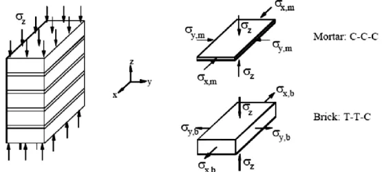
(13) Experimental and Computational Approaches to Historical Masonry Structures: A study in the direction of filling the gap. Figure 2.1: The possible arrangement for stone masonry: (a) rubble masonry; (b) ashlar masonry; (c) coursed ashlar masonry (Lourenço et al., 1998).. Figure 2.2: Different arrangements for brick masonry: (a) American bond; (b) English bond; (c) Flemish bond; (d) stack bond; (e) stretcher bond (Lourenço et al., 1998).. Figure 2.3: Cross section arrangement of masonry walls (Lourenço et al., 1998).. The behaviour of brick and mortar is different from each other. Mortar usually is much softer than brick units. This composite nature and complex geometry of masonry leads to a very complex structural behaviour. Unfortunately, the strength and stiffness properties of the constituent materials do not reflect the structural and stiffness properties of the masonry structure itself (Felix, 1999). This different strain characteristic of composing materials of masonry causes a different 12.
(14) Experimental and Computational Approaches to Historical Masonry Structures: A study in the direction of filling the gap. character in terms of stresses. Under uniaxial compressive loading, the mortar tries to expand laterally more than the stone or brick units. However, because of the continuity between the units and the mortar, combined by cohesion and friction, the mortar is confined laterally by the units. Because of this reason, in a prism under compressive loading normal to bed joints, shear stresses develop at the mortar-brick interface that causes triaxial compression in the mortar and bilateral tension couple with uniaxial compression in the unit (Oliveira, 2009), (Fig.2.4).. Figure 2.4: Masonry prism under compressive loading normal to bed joints and stress states for brick and mortar elements (C: compression, T: tension) (Oliveira, 2009).. Masonry elements (bricks and mortar) have a strong non-linear response as high loads are applied. The mechanical behaviour of bricks is not necessarily homogeneous and isotropic. This means that the properties are not the same in different directions. Also the behaviour changes with respect to tension or compression loads. Generally, the behaviour of bricks is described as elastic-brittle (Hossain et al., 1997). The stress-strain curve of the brick can be obtained, with respect to the direction of the applied load and measured deformation, and characteristic compression strength can be measured (Kaushik et al., 2007). A typical stress-strain curve for bricks in compression is shown in (Fig.2.5). In order to evaluate the bricks module of elasticity (𝐸𝑏 ), (Kaushik et al., 2007) states that the recommended range depends on the compression strength of the brick (𝑓𝑏 ): 150𝑓𝑏 < 𝐸𝑏 < 500𝑓𝑏 Which it can be expressed graphically (Fig.2.6).. 13.
(15) Experimental and Computational Approaches to Historical Masonry Structures: A study in the direction of filling the gap. Figure 2.5: Stress-strain curve for bricks in compression (Kaushik et al., 2007).. Figure 2.6: Variation of modulus of elasticity of brick (Kaushik et al., 2007).. On the other hand, the stress strain curve of new mortar and a characteristic compression strength are obtained by using a simple compression test (Fig.2.7). In order to evaluate the mortar module of elasticity (𝐸𝑚 ), (Kaushik et al., 2007) states that the recommended range depends on the compression strength of the mortar (𝑓𝑚 ) (Fig.2.8): 100𝑓𝑚 < 𝐸𝑚 < 400𝑓𝑚. 14.
(16) Experimental and Computational Approaches to Historical Masonry Structures: A study in the direction of filling the gap. Strain Figure 2.7: stress-strain curve for mortar in compression. (Kaushik et al., 2007). Figure 2.8: Variation of modulus of elasticity of new mortar (Kaushik et al., 2007).. From theory of elasticity (Gere & Timoshenko, 1986), the shear module of elasticity (G) is given as: 𝐺𝑚 =. 𝐸 2(1 + 𝑣). where, 𝑣 = the Poisson’s ratio. The numerical analysis of the historical masonry structures requires the material mechanical properties like axial compression strength. It is not always possible to perform compression test on masonry to obtain the actual strength, although this is the basic structural property for analyzing masonry structures (Christy, 2013). On the other hand, the compressive strength of brick (𝑓𝑏 ) and mortar (𝑓𝑚 ) can be evaluated by standard tests. As stated by (Christy, 2013), the axial strength of 15.
(17) Experimental and Computational Approaches to Historical Masonry Structures: A study in the direction of filling the gap. the unreinforced brick masonry can be predicted from the obtained results of the brick and mortar strength and the strength. The predicted values were compared with the data reported by (Hemant et al., 2007) which included Bennet‘s equation and Dayaratnam‘s equation. While Bennet has given a relationship between the strength of the brick masonry and the strength of the brick and the mortar as: Masonry strength = 0.63𝑓𝑏 0.49 𝑓𝑚 0.32 and Dayaratnam has given a relationship between the strength of brick masonry and the strength of the brick and the mortar as: Masonry strength = 0.275𝑓𝑏 0.5 𝑓𝑚 0.5 the generalized equation proposed by (Christy, 2013) for estimating the axial strength of the brick masonry is: Masonry strength = 0.35𝑓𝑏 𝛼 𝑓𝑚 𝛽 where, 𝛼 and 𝛽 = constants 𝑓𝑏 = strength of brick in MPa 𝑓𝑚 = strength of mortar in MPa generally, the brick strength is greater than the mortar strength, so ‘𝛼’ must be greater than ‘𝛽’ as stated by (Hemant et al., 2007), which are suggested to be: 𝛼 = 0.65, 𝛽 = 0.25. Through the general mechanical behaviour of masonry elements, it appears an important aspect related with the stress-strain curve, which is represented by the softening. It can be defined as the gradual decrease in the mechanical resistance under a continuous increase of the applied load upon the masonry structure. It is a salient feature due to a process of progressive internal crack growth. Such mechanical behaviour is commonly attributed to the heterogeneity of the material, due to the presence of different phases and material defects (Lourenço et al., 1998). This phenomenon is identified by both compressive and tensile failures where it has been observed as degradation of the cohesion in Coulomb friction models. Softening behaviour is highly dependent upon the boundary conditions in the experiments and the size of the specimen (Lourenço et al., 1998). (Fig.2.9) and (Fig.2.10) show characteristic stress-displacement diagrams for quasi-brittle materials in uniaxial compression and tension. The inelastic behaviour for both. 16.
(18) Experimental and Computational Approaches to Historical Masonry Structures: A study in the direction of filling the gap. compression and tension can be described by the integral of the stress-strain diagram, which is represented by the fracture energy Gf.. Figure 2.9: Typical behavior of quasi-brittle materials under uniaxial compression (Lourenço et al., 1998).. Figure 2.10: Typical behavior of quasi-brittle materials under uniaxial tension (Lourenço et al., 1998).. 17.
(19) Experimental and Computational Approaches to Historical Masonry Structures: A study in the direction of filling the gap. 2.3 The acting actions and failure mechanisms of masonry structures In the design and analysis of masonry structures, load intensities are obtained by structural design codes. However, this method is not applicable for old structures since there were no design guidelines at the time of the construction. Hence, the load estimations and their combination is based on historical documents, observations, past experiences and engineering judgment (Özen, 2006). The most common expected loads on a historic structure are: • Self weight of the structure. • Seismic actions. • Differential settlements of supports. • Soil pressure and ground movement. • Creep. • Thermal loads. • Snow loads and ice pressure. • Impact loads. • Surcharge on walls. Self-weight of the structure includes the weight of the structural elements, weight of the architectural elements etc. Since masonry is very strong under compression forces, the masonry structures are usually very resistant to gravity loads. On the other hand, seismic actions and differential settlements of supports are usually the main reasons for the damage or collapse of masonry structures (Mele, 2003). Damage due to support settlement is less common with respect to earthquake damage, since the soil and structure has reached equilibrium with time. However, construction in urban areas can cause the ground profile to change and this may cause support settlement problems.. 18.
(20) Experimental and Computational Approaches to Historical Masonry Structures: A study in the direction of filling the gap. Earthquakes are always the number one enemy of masonry structures erected in highly active seismic zones. In other words, masonry structures are highly vulnerable to earthquakes. The high seismic vulnerability of masonry structures is due to (Mele, 2003): • Highly nonlinear behaviour. • Very small tensile strength. • Uncertain arrangement of blocks and mortar joints. • Significant scatter of mechanical properties throughout the building. • Composite geometry and morphology. • Extreme mass. Determination and application of seismic actions to the analysis model is also a difficult process. Since the lifetime of a historical structure is much longer than that of a contemporary one, the usage of design spectrums derived by using recently registered earthquake data may not be valid for historical structures. Application of seismic actions by the lumped mass assumption is not valid for masonry structures either, since the mass of such kind of buildings is uniformly distributed through the structure (Grillo, 2003).. Types of Failure In the general case of masonry structures, there are three main failure mechanisms (Decanini et al., 2004): a) In-plane failure In-plane resistance of masonry walls is based on mortar strength and brick proportions. If the forces are strong enough to exceed the in-plane strength capacity of the wall, a shear failure will occur. This failure mode is characterized by brittle tensile cracking through the mortar and the masonry unit and a sudden loss of lateral load capacity. b) Out-of-plane failure Seismic or wind loadings induce out-of-plane bending of walls between the restraining floors. Analysis of the failure modes must take into account many different factors, such as boundary conditions, wall compressive strengths, joint tensile strengths, wall stiffness, and applied loadings. 19.
(21) Experimental and Computational Approaches to Historical Masonry Structures: A study in the direction of filling the gap. Walls will typically remain stable under dead load and after cracking if they are within the specified height-to-thickness ratio. If the slenderness ratio is exceeded, the wall needs bracing by either a horizontal brace or vertical columns. Parapets, chimneys, and similar elements extending above the topmost line of restraint are most vulnerable to out of plane forces. c) Connections Out of plane loads cause walls to push against and pull away from the floors that they are connected to. Failure to have a secure connection between the two elements can cause failure by falling brick as well as floor collapse. This type of problem can be corrected and work can be performed while the building is occupied.. Figure 2.1: Basic damage modes of a masonry building (Decanini et al., 2004).. 20.
(22) Experimental and Computational Approaches to Historical Masonry Structures: A study in the direction of filling the gap. Chapter 3. State of Art in Masonry Assessment 3.1 Assessment for masonry structures The preservation of historical structures is important to keep it save through the upcoming future. The historical masonry structures need to be assessed and evaluated in a way to determine and figure out the most risky primary failure mechanisms and provide a strategy for rehabilitation. So in order to have a fully structural assessment, it is needed to have: measurement survey, material tests, soil survey, long-term observations, and structural tests (Teomete and Aktaş, 2010). Finite element models and structural analyses of the historical structures were developed by using the data obtained from destructive and non-destructive tests to characterize the materials of the structure (Binda et al., 2000). Studying the behaviour of the masonry structures is the base of the structural assessment, where several practical structural analyses techniques such as force polygon and the chain rule have been used to determine the reasons for structural damage in various masonry structures (Teomete and Aktaş, 2010), also long-term monitoring helps to increase the knowledge of the real behaviour of the structure and in the planning of maintenance intervention. In the long term, static monitoring requires accurate and very stable systems, able to relate measurements often spaced over long periods of time.. 3.1.1 The importance of historical structures assessment Historical masonry structures were built on ancient times when no appropriate theory and good knowledge were available, where it have been built according to the available knowledge and experience. So many buildings which still exist do not satisfy the present guidelines. Also the recent worldwide earthquakes make people more conscious about the safety of life and property. 21.
(23) Experimental and Computational Approaches to Historical Masonry Structures: A study in the direction of filling the gap. Some of the famous building which becomes valuable in terms of culture and history demand longer service life (Carini and Genna, 2012). So lot of reasons may be claimed for historical structure assessment. It is summarized as follows: -. To eliminate structural problems or distress which results from unusual loading or exposure conditions, inadequate design, or poor construction practices. Distress may be caused by overloads, fire, flood, foundation settlement, deterioration resulting from abrasion, fatigue effects, chemical attack, weathering, inadequate maintenance, etc.. -. To be conform to current codes and standards.. -. To allow the feasibility of changing the use of a structure to accommodate a different use from the present one.. -. Durability problems due to poor or inappropriate construction materials.. -. Design or construction errors.. -. Aggressive environments not properly understood during the design stages.. -. Increased life-span demands made on ageing infrastructure.. -. Exceptional or accidental loading.. -. Varying life span of different structural or non-structural components.. 3.1.2 The procedures of masonry structures assessment The historical structures assessment comprises, in general, the following phases/actions: -. Acquisition of documented data about the building.. -. Detailed survey of the existing condition of the building.. -. Elaboration of the diagnosis (eventually, with the carrying of tests).. -. Assessment of the structural safety.. -. Design of the solutions for the intervention.. -. Execution of the intervention.. These phases/actions depend on the actual conditions of the structure and on the objectives to be fulfilled by the assessment, where it can be by different forms, going from the non-invasive (with the imposition or not of restrictions of use), passing through different kinds of works of repair and/or strengthening, until, eventually, partial demolition followed by reconstruction. The 22.
(24) Experimental and Computational Approaches to Historical Masonry Structures: A study in the direction of filling the gap. decisions about the solutions to be adopted on the intervention will still be submitted to a costbenefit analysis, in which all the relevant aspects will be considered, namely, the compatibility of the structural safety with respect to the cultural value of the building, and the cost to be as low as possible (CIB Commission, 2010).. 3.2 Experimental techniques for masonry assessment Large number of monuments are located in seismic areas, where it is needed to be controlled and investigated in order to keep it save and stable. The methodological approach to analyse the existing historical masonry structures requires a series of preliminary investigations by using experimental techniques which provide details of the structure's mechanical characteristics and define the structural behaviour of the monument. There are many challenges can be found during the analysis of historical structures, due to the complexity of its geometry, the variability of the properties of different materials, and the construction techniques have been used. Masonry structures evaluation techniques can involve varying levels of damage or deconstruction of the masonry. Especially in historic structures, even relatively minor damage can result in expensive and difficult repairs. The use of non-destructive methods helps limit the damage caused by the testing. Additionally, gathering information about the existing masonry provides designers with confidence that they understand the current conditions and the potential causes of any distress. This knowledge and confidence typically lead to better planning and more effective designs, ultimately minimizing modifications and additions to the historic structure. (Donald, 2010) The techniques are used in the diagnosing the historical structures are divided into destructive, semi-destructive and non-destructive methods. Destructive tests can be applied to samples and natural-scale structural elements. Both are completely destroyed during the tests. For this reason only a few representative natural-scale elements are subjected to such tests. Semi-destructive tests are also applied to samples and natural-scale elements and structures but they involve a small intrusion into the structure of the material, resulting local loss of service properties and requiring repair. There is no such intrusion in the case of non-destructive tests which are applied to mainly natural-scale elements and structures. Moreover, non-destructive tests can be applied to the same elements and structures many times and at different times whereby such methods are suitable for. 23.
(25) Experimental and Computational Approaches to Historical Masonry Structures: A study in the direction of filling the gap. the diagnostic testing of building structures during both their construction and many years of their service life (Rossi, 1990). NDT has increasingly become a major part of masonry field work. As many of the historical masonry buildings are aging and need to maintenance and repair, also it is a viable alternative to evaluate their condition and strength instead of using techniques which would limit their use or cause destruction of the buildings. On the other hand can be used to evaluate structures stability against all the external actions. The information obtained by NDT is necessary to determine the mechanical parameters for the analysis of the historical monuments and comprehension of its structural behaviour, (Akbulut and Akoz, 2004). The assessment process presented in the chart below summarises the whole phases of this study, it can be considered as a synthesis of all investigation process which play an important role in the diagnosis and analysis of historical structures. This flow chart does not present something new but it is an attempt to indicate logical steps in the assessment with respect to the experimental and computational approaches. The assessment of structures starts from the observation of any failure that indicate the presence of structural defect which cause a condition of instability. Then it develops to deal with analysing all the causes’ possibilities which may somehow be related to the defect itself. The analysis of the defect that may be found in the structure is a significant stage in the assessment process, based on accurate experimental tools and analytical surveys, where the obtained data lead to a number of possible diagnosis hypothesis. These are characterized by some degree of uncertainty. The presence of different possible reasons must be considered at the assessment process supported by operative tools.. 24.
(26) Experimental and Computational Approaches to Historical Masonry Structures: A study in the direction of filling the gap. The Assessment process physical structure failure. performance failure Visual check; Color photographs with standard chromatic scales; Infra-red photographs; Stereo-photographs; Dimensional survey with metric tools. Pre-assessment. Analysis. Detailed inspection. List of defects. Defects observation; Specific bibliographies; Study of building materials and components technology, etc.; Historical analysis of: building technologies used at time of building construction; construction technology used for the building component Diagnostic tree. pre-assessment analysis. check list of causes. experimental / analytical survey. Assessment. The Assessment tools. diagnostic analysis. the results of diagnosis process. cause identification and Safety evaluation. 25. Quantative/qualitative non-destructive methods for on-site tests; Quantative/qualitative destructive methods for on-site tests; Researches with sample extraction for laboratory analysis; simulation on scale model Analysis of the experimental survey results by physical/mathematical methods; Fault tree; Diagnostic tree; numerical methods and FEM models; Analysis of : components design process, components construction process, components assembling process, external contextual data, use patterns of inner environment, maintenance interventions performed during building life cycle.
(27) Experimental and Computational Approaches to Historical Masonry Structures: A study in the direction of filling the gap. Chapter 4. Review of Experimental Techniques for Masonry. Experimental determination of material properties The properties of masonry structures are influenced by many factors, such as; the construction technique, type of mortar, physical properties of the materials used for the mortar, and state of masonry units before casting. Where it can be deduced that in the experimental determination of mechanical properties of masonry structures, a large number of variables can be considered. As known that the structural analysis requires the material properties, for example, the modulus of elasticity of masonry is required for the linear static analysis. Stress-strain curves of masonry are required for detailed non-linear analysis of masonry structures. So There are many ways for obtaining the mechanical properties of masonry structures which are divided into destructive, semi destructive, and none destructive techniques. Which can be done in situ or in the laboratory, where it follows by many standards, such as ASTM (American Society for Testing and Materials), RILEM (The International Union of Laboratories and Experts in Construction Materials), and BS (British Standards), which are mainly used to describe the experimental techniques in this chapter.. 26.
(28) Experimental and Computational Approaches to Historical Masonry Structures: A study in the direction of filling the gap. 4.1 Testing techniques for masonry unit These test techniques provide various testing procedures commonly used for evaluating mechanical characteristics of masonry units (Fig. 4.01).. Mechanical characteristics of masonry UNIT. Laboratory testing. In-situ testing. Non destructive tests. Semi destructive tests. Unit compressive strength by using rebound hammer. Testing on specimens made of new materials. Unit shear strength using hydraulic jack Unit shear strength using flat-jacks. Testing on walls from site sampling. Compressive strength, modulus of rupture for unit Bond strength of unit using bond wrench. Splitting tensile strength using site- cores Compressive strength, modulus of elasticity, and poisson's ratio using site- cores. Splitting tensile strength of units Figure 4.01: techniques for determining the mechanical properties of masonry units.. 4.1.1 Compressive strength and modulus of rupture for masonry. unit Scope This test covers the procedures for sampling and testing masonry units; it includes Young’s modulus, compressive strength, and Poisson’s ratio, for both brick units and masonry core specimens.. 27.
(29) Experimental and Computational Approaches to Historical Masonry Structures: A study in the direction of filling the gap. Apparatus -. Compression Loading Device: The loading device shall be of sufficient capacity to apply load at a rate conforming to the test requirements. The loading device may be equipped with a displacement transducer that can be used to advance the loading at a specified rate.. -. Bearing Surfaces: Two steel plates are used to transmit the axial load to the ends of the specimen.. -. Strain/Deformation Measuring Devices: Deformations or strains may be determined from data obtained by electrical resistance strain gages, compress meters, linear variable differential transformers (LVDTs), or other suitable means. 1. Determination of Axial Strain: The design of the measuring device shall be such that the average of at least two axial strain measurements can be determined. Measuring positions shall be equally spaced around the circumference of the specimen, close to mid-height. The gauge length over which the axial strains are determined shall be at least ten grain diameters in magnitude. 2. Determination of Lateral Strain: The lateral deformations or strains may be measured by any of the methods. Either circumferential or diametric deformations (or strains) may be measured. A single transducer that wraps around the specimen can be used to measure the change in circumference. At least two diametric deformation sensors shall be used if diametric deformations are measured. These sensors shall be equally spaced around the circumference of the specimen close to mid-height. The average deformation (or strain) from the diametric sensors shall be recorded. (ASTM D7012, 2013). Procedure Sampling: -. Selection of Specimens: solid masonry units shall be selected representative of the lot of units from which they are selected and shall include specimen’s representative of the. 28.
(30) Experimental and Computational Approaches to Historical Masonry Structures: A study in the direction of filling the gap. complete range of colours, textures, and sizes. Specimens shall be free of or brushed to remove dirt, mud, mortar, or other foreign materials -. The specimens for each sample shall be selected from cores representing a valid average of the type of masonry under consideration. This can be achieved by visual observations of the structure.. -. Desirable specimen length to diameter ratios are between 2:1 and 2.5:1. Specimen length to diameter ratios of less than 2:1 are unacceptable.. -. The number of specimens required to obtain a specific level of statistically results.. Modulus of Rupture (Flexure Test): -. The test specimens shall consist of whole full-size units. At least five specimens shall be tested.. -. Support the test specimen flatwise, apply the load in the direction of the depth of the unit to the upper surface through a steel bearing plate.. -. The rate of loading shall not exceed (8896 N)/min.. Compressive Strength test: -. Test brick specimens flatwise, the load shall be applied perpendicular to the bed surface of the brick with the brick in the stretcher position.. -. The upper bearing shall be a spherically seated, hardened metal block firmly attached at the centre of the upper head of the machine. The centre of the sphere shall lie at the centre of the surface of the block in contact with the specimen. The block shall be closely held in its spherical seat, but shall be free to turn in any direction.. -. Apply the load, up to one half of the expected maximum load, at any convenient rate, after which, adjust the controls of the machine so that the remaining load is applied at a uniform rate in not less than 1 nor more than 2 min.. Strain/ Deformations test: -. The spherical seat shall rotate freely in its socket before each test. Where the lower platen shall be placed on the base or actuator rod of the loading device. The bearing faces of the upper and lower platens and of the test specimen shall be wiped clean, and the test specimen 29.
(31) Experimental and Computational Approaches to Historical Masonry Structures: A study in the direction of filling the gap. shall be placed on the lower platen. The upper platen shall be placed on the specimen and aligned properly. -. The axial load shall be applied continuously and without shock until the load becomes constant, is reduced, or a predetermined amount of strain is achieved.. -. Readings of deformation shall be observed and recorded at a minimum of ten load levels that are evenly spaced over the load range. (ASTM D7012, 2013). Data Analysis -. the modulus of rupture of each unit can be calculated as given in (NCMARDL, 1993): 𝑆=. 𝑙 3𝑊(2 − 𝑥) 𝑏𝑑 2. where: S = modulus of rupture of the specimen at the plane of failure, Pa W = maximum load indicated by the testing machine, N l = distance between the supports, mm b = net width of the specimen at the plane of failure, mm d = depth of the specimen at the plane of failure, mm x = average distance from the mid-span of the specimen to the plane of failure measured in the direction of the span along the centreline of the bed surface subjected to tension, mm -. compressive strength of each unit can be calculated as given in (ASTM C67, 2013): 𝐶=. 𝑊 𝐴. where: C = compressive strength of the specimen, Pa W = maximum load, N A = average of the gross areas of the upper and lower bearing surfaces of the specimen, m2, -. the relation between the shear and bulk moduli and Young’s modulus and Poisson’s ratio are: 𝐺=. 𝐸 2(1 + 𝑣) 30.
(32) Experimental and Computational Approaches to Historical Masonry Structures: A study in the direction of filling the gap. 𝐾=. 𝐸 3(1 − 2𝑣). where: G = shear modulus, K = bulk modulus, E = Young’s modulus, v = Poisson’s ratio. -. Axial strain, εa can be calculated as follows: 𝜀𝑎 =. ∆𝐿 𝐿. where: L = original un-deformed axial gauge length, mm ΔL = change in measured axial gauge length, mm -. Lateral strain, εl can be calculated as follows: 𝜀𝑙 =. ∆𝐷 𝐷. where: D = original un-deformed diameter, mm ΔD = change in diameter (positive for increase in diameter), mm -. The stress-versus-strain curves can be plotted for the axial and lateral directions. The complete curve gives the best description of the deformation behaviour of masonry unit having nonlinear stress-strain relationships at low- and high stress levels.. -. Tangent modulus at a stress level that is some fixed percentage (usually 50 %) of the maximum strength.. -. Average slope of the more-or-less straight-line portion of the stress-strain curve. The average slope shall be calculated either by dividing the change in stress by the change in strain or by making a linear least squares fit to the stress-strain data in the straight-line portion of the curve.. 31.
(33) Experimental and Computational Approaches to Historical Masonry Structures: A study in the direction of filling the gap. -. Secant modulus, usually from zero stress to some fixed percentage of maximum strength.. -. The value of Poisson’s ratio, υ, is greatly affected by nonlinearities at low-stress levels in the axial and lateral stress-strain curves. It is desirable that Poisson’s ratio shall be calculated from the following equation: 𝑣=−. slope of axial curve E = − slope of lateral curve slope of lateral curve. Figure 4.02: Stress-strain plot obtained by the technique (ASTM D7012, 2013).. Conclusion Masonry stress–strain properties are required in the nonlinear analyses of structures. However, compressive stress–strain relationships for masonry are determined by testing masonry prism. Masonry is typically a nonelastic, nonhomogeneous, and anisotropic material composed of two materials of quite different properties: stiffer bricks and relatively softer mortar. Under lateral loads, masonry does not behave elastically even in the range of small deformations. Masonry is very weak in tension because it is composed of two different materials distributed at regular intervals and the bond between them is weak. Therefore, masonry is normally provided and expected to resist only the compressive forces, during compression of masonry prisms constructed with stronger and stiffer bricks, mortar of the bed joint has a tendency to expand laterally more than the bricks because of lesser stiffness. However, mortar is confined laterally at the brick– mortar interface by the bricks because of the. 32.
(34) Experimental and Computational Approaches to Historical Masonry Structures: A study in the direction of filling the gap. bond between them; therefore, shear stresses at the brick-mortar interface result in an internal state of stress which consists of triaxial compression in mortar and bilateral tension coupled with axial compression in bricks. This state of stress initiates vertical splitting cracks in bricks that lead to the failure of the prisms.. References ASTM C67 −13a. (2013). Standard Test Methods for Sampling and Testing Brick and Structural Clay Tile. ASTM standards, 13. ASTM D7012 − 13. (2013). Standard Test Methods for Compressive Strength and Elastic Moduli of Intact Rock Core Specimens under Varying States of Stress and Temperatures. ASTM standards, 9. GARCÍA, D., SAN-JOSÉ, J., GARMENDIA, L., & LARRINAGA, P. (2011). "Comparison between experimental values and standards on natural stone masonry mechanical properties." Construction and Building Materials 28: 444-449. NCMARDL. (1993). Evolution Of Compressive Strength Of In Situ Masonry. USA: National Concrete Masonry Association Research and Development Laboratory, 75. HOSSAIN, MD., ALI, SK., & RAHMAN, M. (1997). "Properties Of Masonry Constitute." Journal of Civil Engineering, 21. BINDA, L., SAISI, A., & TIRABOSCHI, C. (2000). "Investigation procedures for the diagnosis of historic masonries." Construction And Building Materials 14: 199-233. BINDAL, L., MODENA, C., BARONIAL, G., & ABBANEO, S. (1997). "Repair And Investigation Techniques For Stone Masonry Walls." Construction and Building Marerinls 11 (3): 133-142.. 4.1.2 Splitting tensile strength for masonry unit Scope In this test a line load produced along surface of the masonry specimen. The compressive load applied to the masonry unit samples, imposed by means of bearing rods, results in a tensile stress distributed over the height of the specimen for it’s the split length. This loading induces tensile stresses on the plane containing the applied load and relatively high compressive stresses in the area immediately around the applied load. This test method can be conducted with the rod oriented either in the longitudinal direction or in the transverse direction of the bed face.. 33.
(35) Experimental and Computational Approaches to Historical Masonry Structures: A study in the direction of filling the gap. Apparatus . Bearing Rods: paired steel bearing rods with diameters within 1 ⁄8 to 1⁄12 of the specimen height, of a length greater than the length of the intended test area, and of straightness within 0.5 % of the specimen length shall be provided for each unit. Bearing rods that meet the straightness requirement can be reused.. . Supplemental Bearing Bar or Plate: If the diameter or largest dimension of the upper bearing face or lower bearing block is less than the length of the specimen to be tested, a supplementary bearing bar or plate shall be used. The contact surfaces of the bar or plate shall be machined to within 0.05 % of planeness as measured on any line of contact of the bearing area. The bearing bar or plate shall have a width of at least 51 mm, and a thickness not less than the distance from the edge of the spherical or rectangular bearing block to the end of the specimen. The bar or plate shall be used in such a manner that the load will be uniformly applied over the entire intended split length of the specimen.. . Testing Machine: The upper, hardened metal bearing face shall be spherically seated and attached at the centre of the upper head of the machine. The centre of the sphere shall lie at the centre of the surface of the plate in contact with the specimen.. Procedure Laboratory Samples as states in (ASTM C1006, 2007): -. Positioning Bearing Rods: mark the intended location of the split surface on either faces, stretcher or normally exposed faces for transverse splitting, and end faces for longitudinal splitting. Spread a gypsum capping compound. -. The bearing rods shall be positioned no closer to a free edge than one half the specimen height.. -. Test Alignment: Align the rods with the centreline of the plates, and centre the rods in the transverse direction. Support the specimen on compressible rods or tubes that are 1.6 mm smaller in diameter than the bearing rods. Remove the compressible rods when the specimen is held in vertical orientation by the testing-machine platens. 34.
(36) Experimental and Computational Approaches to Historical Masonry Structures: A study in the direction of filling the gap. -. Rate of Loading: Apply the load without impact and load continuously at a rate less than 8900 N/min.. -. Measurement: Determine the height of the specimen to the nearest 2.5 mm by averaging three heights measured near the ends and the middle and on a plane perpendicular to the bed surface. Determine the split length of the specimen to the nearest 2.5 mm by averaging at least two measurements taken on the plane of the bearing rods. The split length is the actual net length of the failure plane of the bearing rods and is equal to the gross length of the unit minus the length of any voids along this plane.. Site-Cores Samples as states in (ASTM C1006, 2007): -. Draw diametric lines on each end of the specimen using a suitable device that will ensure that they are in the same axial plane.. -. Determine the diameter of the test specimen to the nearest 0.25 mm by averaging three diameters measured near the ends and the middle of the specimen and lying in the plane containing the lines marked on the two ends. Determine the length of the specimen to the nearest 2 mm by averaging at least two length measurements taken in the plane containing the lines marked on the two ends.. -. Positioning Using Marked Diametric Lines: Centre one of the plywood strips along the centre of the lower bearing block. Place the specimen on the plywood strip and align so that the lines marked on the ends of the specimen are vertical and cantered over the plywood strip. Place a second plywood strip lengthwise on the cylinder, cantered on the lines marked on the ends of the cylinder. The supplementary bearing bar or plate, when used, and the centre of the specimen are directly beneath the centre of thrust of the spherical bearing block.. -. Positioning by Use of Aligning Jig: Position the bearing strips, test cylinder, and supplementary bearing bar by means of the aligning jig and centre the jig so that the supplementary bearing bar and the centre of the specimen are directly beneath the centre of thrust of the spherical bearing block.. -. Rate of Loading: Apply the load continuously and without shock, at a constant rate within the range 0.7 to 1.4 MPa/min splitting tensile stress until failure of the 35.
(37) Experimental and Computational Approaches to Historical Masonry Structures: A study in the direction of filling the gap. specimen. Record the maximum applied load indicated by the testing machine at failure. Note the type of failure and the appearance of the masonry core.. Figure 4.03: Masonry unit testing setup (ASTM C1006, 2007).. Figure 4.04: masonry site-core samples (Mazzotti and Sassoni, 2013).. Figure 4.05: Specimen Positioned in the testing machine (ASTM C1006 ,2007).. 36.
(38) Experimental and Computational Approaches to Historical Masonry Structures: A study in the direction of filling the gap. Data Analysis -. the splitting tensile strength of the specimens can be calculated as follows: 𝑓𝑡 =. 2𝑃 𝜋𝐿𝐻. where: ft = splitting tensile strength, kPa P = maximum applied load indicated by the testing machine, kN L = split length, mm, gross length minus the length of any voids along the failure plane of the bearing rods. H = distance between rods, mm Conclusion Splitting tensile strength is generally greater than direct tensile strength and lower than flexural strength (modulus of rupture). Where it is used in the design of masonry structural and evaluate the shear resistance. Tensile failure occurs rather than compressive failure because the areas of load application are in a state of triaxial compression, thereby allowing them to withstand much higher compressive stresses than would be indicated by a uniaxial compressive strength test result.. References ASTM C1006 − 07. (2007). Standard Test Method for Splitting Tensile Strength of Masonry Units. ASTM standards, 3. MAZZOTTI, C., SASSONI, E., & PAGLIAI, G. (2013). "Determination of shear strength of historic masonries by moderately destructive testing of masonry cores." Construction and Building Materials 54: 421–431.. 4.1.3 Masonry flexural bond strength by bond wrench test Scope Bond strength between mortar and masonry unit is a significant factor in the performance of a masonry system. This test evaluates the flexural bond strength for masonry mortar bed joint, both in situ and laboratory prepared samples. In which It is possible to check the quality of mortar under a given conditions.. 37.
(39) Experimental and Computational Approaches to Historical Masonry Structures: A study in the direction of filling the gap. Apparatus -. Tools for sample preparation: 1. Prism alignment jig. 2. Mortar joint template 3. Mechanical paddle-type mortar mixer 4. Flow table, flow mold, and caliper 5. Cone penetrometer, unit measure, straightedge, spatula, tapping stick, and spoon.. -. Bond strength test apparatus:. A bond wrench is a lever that can be clamped to the top unit of a prism and is of such mass and proportion that the stresses imposed by the bond wrench at the start of a test do not exceed 0.1 N/mm2 in either flexural compressive stress or flexural tensile stress. Load may be applied in a number of different ways. Four typical methods are as follows: 1. By filling a container hanging from the moment arm of the wrench with lead shot or an alternative material, delivered in a steady stream. The amount delivered should be assessed by weighing on a balance accurate to within ±25g. 2. By driving a mass out along the moment arm at a steady rate and in such a way as not to cause shock or other disturbance. 3. By operation of a hydraulic ram of a suitable capacity attached to a point along the moment arm via a steel wire or articulated tie. 4. By manual application of force via a measuring device such as a load cell. Other methods of load application may also be satisfactory provided the accuracy is comparable. In fact when the re-pointing and the jointing are weak the failure of the bond can be very sudden; in that case the load rate can be kept as low as possible by substituting the lead shots with a constant water. (Fig. 4.06) illustrates the principle of the bond wrench applied to re-pointing. (Binda et al., 2005) -. clamping device:. Clamping device is required which can firmly clamp the unit one down from the top of the prism whilst not applying any significant bending moment to the joints below. In order to calibrate the equipment determine the mass of the wrench to ±10g, the distance from the inside edge of the 38.
(40) Experimental and Computational Approaches to Historical Masonry Structures: A study in the direction of filling the gap. outer clamp face to the loading notch to within ±2 mm and the distance from the inside edge of the outer clamp face to the centre of gravity of the wrench to within ±2 mm. The type with the driven mass will require the measurements to be made with the mass in the start position. Where a container is used it should be in place but empty; if a jack is used the wire should be attached to the arm but slack. -. Displacement measurement:. To enable the monitoring of the strength of pointing when its bond strength is very low, 4 displacement transducers can be applied on the clamping devices near the area where the highest tensile stresses are applied corresponding to the most external point of the pointing and at the end of jointing so that the displacements of these two important points can be measured.. Figure 4.06: Bond Wrench Testing Apparatus (ASTM C1072, 2013).. Figure 4.07: Basic principle of bond wrench test a) before and b) after the loading (Park, 2013). 39.
(41) Experimental and Computational Approaches to Historical Masonry Structures: A study in the direction of filling the gap. Procedure -. Specimens Sampling:. In situ specimens 1. The sample shall have at least five bed joints, and contains one or more prisms. 2. Where mortar fins and extrusions project from the specimen to the extent that they may interfere with the attachment of the bond wrench, they shall be removed without causing damage to the specimen. Remove only enough material to enable proper attachment of the bond wrench. Laboratory specimens 1. Fabricate a set of stack-bonded test prisms containing a total of not less than 15 mortar joints. Each prism shall have no more than 5 joints. 2. Proportion mortar materials by weights equivalent to volume proportions to be used in prism construction. Then mix mortar in a mechanical paddle-type mortar mixer. 3. Fabricate prism specimens. 4. Cure prism specimens. Test Procedures: The procedures according to (ASTM C1072, 2013) as follows: 1. Place the prism vertically in the support, and clamp firmly into a locked position using the lower clamping bracket. Orient the prism so that the face of the joint intended to be subjected to flexural tension is on the same side of the specimen as the clamping bolts. The prism shall be positioned at the required elevation that results in a single brick projecting above the lower clamping bracket as shown in (Fig.4.08). 2. Attach the upper clamping bracket to the top unit. Tighten each clamping bolt using a torque not greater than 5.7 N·m. 3. Lower base support away from the bottom of the prism so that no contact occurs during testing. 4. Apply the load at a uniform rate so that the total load is applied in not less than 1 min or more than 3 min. Measure load to an accuracy of 62 % with maximum error of 22 N.. 40.
(42) Experimental and Computational Approaches to Historical Masonry Structures: A study in the direction of filling the gap. Figure 4.08: Bond Wrench test, loading stage with displacements measurements transducers (Binda et al., 2005).. Figure 4.09: Bond Wrench test, failure after reaching the ultimate bond strength (Binda et al., 2005).. Data Analysis -. the flexural strength as given by (Park, 2013): 𝐹𝑔 =. 6(𝑃𝐿 + 𝑃𝐼 𝐿𝐼 ) (𝑃 + 𝑃𝐼 ) − 𝑏𝑑 2 𝑏𝑑. where: 𝐹𝑔 = Flexural tensile strength, MPa 𝑃 = Maximum applied load, N 𝑃𝐼 = Weight of loading arm, N 𝐿 = Distance from center of prism to loading point, mm 𝐿𝐼 = Distance from center of prism to centroid of loading arm, mm 41.
Figura


+7


Documenti correlati
Italia e nel Diritto Privato Europeo” – Ciclo XXII. - TESI DI
In the past decades, the need to study gender has for many people become self-evident. We have learned to see that, on the one hand, all known societies have
è fondamentale, durante ogni momento del lavoro, non reprimere nei bimbi e nei disabili quelle emozioni, che convenzionalmente tendiamo a definire come “brutte” (come la tristezza
Nel momento in cui il regno di Napoli perdeva la propria indipendenza travolto dall'imperialismo franco-spagnolo d'inizio Cinquecento, la repubblica di Venezia
In the following, we derive a model for access requests and service operation in the cell, and show how to compute network utilization, access delay, and in general how to assess
7: critical state line and normal compression lines in different planes (modified from Atkinson and Bransby, 1978). The m echanical behaviou r of over-consolid ated clays is qu ite
The complex modulus properties of viscoelastic materials depend strongly on temperature, in ways particular to the composition of the material. Each viscoelastic material has
Purtroppo è così, siamo spinti dalla grande curiosità, dalla frenesia di poter disporre rapidamente di quel che si può (un po’ anche perché la stessa tecnologia non sta ad
