Angelica Lo Duca
Towards
a Secure Cooperation Mechanism
for Challenging Networks
Anno 2012
UNIVERSITÀ DI PISA
Scuola di Dottorato in Ingegneria “Leonardo da Vinci”
Corso di Dottorato di Ricerca in
Ingegneria dell’Informazione
Informatica, Elettronica, Telecomunicazione
Tesi di Dottorato di Ricerca
Sommario
Una Challenging Network (CN) `e un paradigma di rete che si adatta ai problemi dell’ambiente, al fine di garantire la comuni-cazione tra i nodi. Uno dei problemi pi`u importanti di una CN `e quello di garantire la cooperazione sicura tra i nodi. In questo lavoro descrivo il problema della cooperazione sicura in tre tipi di CNs: le Underwater Acoustic Networks (UANs), le Delay Tolerant Networks (DTNs) e le Publish/Subscribe Networks (PSNs). Una UAN `e un paradigma che permette la comunicazione tra nodi sub-acquei equipaggiati con modem acustici. Poich`e il canale acustico per sua natura `e un canale aperto, un avversario, sufficientemente equipaggiato, potrebbe intercettare i messaggi che attraversano la rete. In questo lavoro descrivo una suite crittografica, in grado di proteggere la comunicazione tra i nodi acustici. Una DTN `e un paradigma di rete che garantisce la consegna dei messaggi anche in presenza di partizioni della rete. Una DTN si basa sull’assunzione implicita che i nodi cooperino per il routing dei messaggi. Co-munque, questa assunzione non pu`o essere soddisfatta quando sono presenti nella rete nodi maliziosi che agiscono da blackholes in modo da attrarre o cestinare volontariamente i messaggi. In questo la-voro propongo un protocollo basato sul concetto di reputazione al fine di contrastare i nodi blackholes. Una PSN e’ un paradigma di rete che permette la comunicazione da nodi publishers a nodi subscribers, attraverso una infrastruttura chiamata Dispatcher. In questo lavoro presento una PSN sicura in grado di supportare la cooperazione tra le organizzazioni. Il servizio `e basato sulla nozione di gruppo di sicurezza, composto da un insieme di brokers che rap-presentano le organizzazioni e che garantiscono la confidenzialit`a e l’integrit`a nella consegna dei messaggi.
Abstract
A Challenging Network (CN) is a network paradigm adapting to the many issues of the environment in order to guarantee the com-munication among nodes. One of the most important issues of a CN is the problem of secure cooperation among nodes. In fact, an attacker, either internal or external, may constitute a threat for the network. In this work I investigate the problem of secure cooperation in three kinds of CNs: the Underwater Acoustic Net-works (UANs), the Delay Tolerant NetNet-works (DTNs) and the Pub-lish/Subscribe Networks (PSNs). A UAN is a network paradigm allowing communication among underwater nodes equipped with acoustic modems. Since the acoustic channel is an open medium, an attacker conveniently equipped could intercept the messages traversing the network. In this work I describe a cryptographic suite, aimed at protecting the communication among underwa-ter acoustic nodes. A DTN is a network paradigm guaranteeing message delivery even in presence of network partitions. A DTN relies on the implicit assumption that nodes cooperate towards message forwarding. However, this assumption cannot be satisfied when there are malicious nodes acting as blackholes and voluntar-ily attracting and dropping messages. In this work I propose a reputation-based protocol for contrasting blackholes. A PSN is a network paradigm allowing communication from publishers to sub-scribers by means of an infrastructure, called Dispatcher. In this work I present a secure PSN conceived to support cooperation be-tween organizations. The service is based on the notion of security group, an overlay composed of brokers representing organizations that guarantees confidentiality and integrity in end-to-end delivery of messages and supports clients mobility.
Acknowledgments
This thesis has been prepared while I was working at the Dipar-timento di Ingegneria della Informazione, of University of Pisa. I would like to thank my advisor, prof. Gianluca Dini, for his sup-port, his high expertise and humanity and for his helpful comments during the last years. I would like to thank also prof. Andrea Caiti and his stu↵ for their cooperation with my work. A big thank you to my family for having encouraged me in all situations. I would like to thank also Andrea, for his loving support and his patience during the last years. Last but not least, I would like to thank God, because every day He gives me the strength to walk across this journey of the life.
Grazie di cuore a tutti!
Contents
1 Introduction 17 1.1 Introduction . . . 17 1.2 Security Issues . . . 18 1.3 Evaluation Criteria . . . 19 1.3.1 Security Requirements . . . 19 1.3.2 Attacks E↵ects . . . 20 1.4 Static Networks . . . 20 1.4.1 Security Requirements . . . 21 1.4.2 Attacks E↵ects . . . 21 1.5 Dynamic Networks . . . 22 1.5.1 Security Requirements . . . 22 1.5.2 Attacks E↵ects . . . 23 1.6 Mixed Networks . . . 24 1.6.1 Security Requirements . . . 25 1.6.2 Attacks E↵ects . . . 26 1.7 Discussion . . . 26 1.8 Conclusions . . . 272 Underwater Acoustic Networks 29 2.1 Introduction . . . 29
2.2 System Model . . . 32
2.3 Threat Model . . . 35
2.4 The Cryptographic Suite . . . 36
2.4.1 Confidentiality . . . 36
2.4.2 Authenticity . . . 37
2.4.3 Group Key Management . . . 38
2.4.4 Experimental tests . . . 41 9
10 CONTENTS
2.5 Small-medium scale system . . . 43
2.6 Large Scale System . . . 43
2.6.1 FLOOD . . . 44
2.6.2 SeFLOOD . . . 48
2.6.3 Performance evaluation . . . 54
2.7 Security Analysis . . . 58
2.7.1 Spoofing-based attack against integrity . . . 59
2.7.2 Spoofing-based Denial of Service (DoS) attack 59 2.7.3 Node compromision . . . 59
2.8 Conclusions . . . 60
3 Delay Tolerant Networks 61 3.1 Introduction . . . 61
3.2 Related Work . . . 64
3.3 System Model . . . 66
3.3.1 Adversary Model . . . 67
3.4 RCAR . . . 68
3.4.1 The concept of Reputation . . . 68
3.4.2 The Reputation Update Protocol . . . 71
3.4.3 The aging mechanism . . . 74
3.5 Performance Evaluation . . . 76
3.5.1 Node List Length . . . 78
3.5.2 Delivery Ratio . . . 79
3.5.3 Attraction Ratio . . . 82
3.5.4 Average Delay . . . 84
3.5.5 Total number of sent messages . . . 85
3.6 Conclusions . . . 87
4 Publish/Subscribe Systems 89 4.1 Introduction . . . 89
4.2 Security Requirements . . . 91
4.3 Secure Pub-Sub System . . . 92
4.3.1 Keys and Certificates . . . 93
4.3.2 The group admission protocol . . . 94
4.3.3 Management of clients . . . 97
4.3.4 Communication between Security Groups . . 97
CONTENTS 11
4.4.1 The SSLTransport . . . 99
4.4.2 The Group Manager . . . 99
4.4.3 The ExtendedDispatchingService . . . 100
4.5 Related Works . . . 101
List of Tables
1.1 Comparison of challenging networks requirements
and attacks countermeasures. . . 24
2.1 Configuration parameters for Scenario L. . . 41
2.2 Simulation parameters. . . 56
3.1 Configuration parameters. . . 77
List of Figures
1.1 A UAN. . . 21
1.2 A DTN. . . 23
1.3 A Pub/sub network. . . 25
2.1 The surveillance network. . . 33
2.2 The point-to-point communication model. . . 34
2.3 The one-to-many communication model. . . 34
2.4 Key Chain. . . 38
2.5 Key Tree. . . 40
2.6 The tested scenario. . . 41
2.7 Average Delivery Ratio with security and without security. . . 42
2.8 An example of topology. . . 44
2.9 The FLOOD protocol. . . 46
2.10 A DoS attack. . . 47
2.11 The CKDP applied to FLOOD. . . 50
2.12 . . . 55
2.13 Discovery Messages in Sparse and Dense Scenarios. 57 2.14 Discovery Bits, Add Bits and Del Bits in Sparse and Dense Scenarios. . . 57
3.1 Flow Diagram of the RCAR algorithm. . . 70
3.2 Nodes List Length Distribution. . . 79
3.3 Delivery Ratio vs Network Area Size. . . 79
3.4 Delivery Ratio Increase vs Network Area Size. . . . 80
3.5 Delivery Ratio vs Number of malicious nodes. . . . 80 3.6 Delivery Ratio Increase vs Number of malicious nodes. 81
16 LIST OF FIGURES
3.7 Attraction Ratio vs Network Area. . . 82
3.8 Attraction Ratio Increase vs Network Area. . . 82
3.9 Attraction Ratio vs Number of malicious nodes. . . 83
3.10 Attraction Ratio Increase vs Number of malicious nodes. . . 83
3.11 Average Delay vs Network Area. . . 85
3.12 AverageDelay vs Number of Blackholes. . . 85
3.13 Total number of sent messages vs Network Area Size. 86 3.14 Total number of sent messages vs Number of mali-cious nodes. . . 86
4.1 A Security Group. . . 92
4.2 Group admission protocol. . . 95
Chapter 1
Introduction
Cominciate col fare ci`o che `e necessario, poi ci`o che `e possibile. E all’improvviso vi sorprenderete a fare l’impossibile.
Francesco d’Assisi (1182–1226)
1.1
Introduction
A Challenging Network (CN) is a network which is able to adapt to the specificity of the environment. An example of CN is the Underwater Acoustic Network (UAN) [1], which is characterized by long delays, high packet loss and low bandwidth. Another example of CN can be considered the Delay Tolerant Network (DTN) [2], which is a partitioned network, where the connectiv-ity among nodes is not guaranteed. As a further example of CN, we have the Publish/Subscribe Network (PSN) [3], which is char-acterized by the presence of many clients, acting one independently on the others.
Each CN presents issues depending on the specificity of the environment. However, we can classify them in three families: a) static networks, b) dynamic networks, c) mixed networks.
In the static networks, all the nodes are well known before the network deployment and usually they do not change during the
18 CHAPTER 1. INTRODUCTION network lifetime. An example of static networks is the UAN, which has a limited number of nodes, as they are very expensive.
In the dynamic networks, the nodes are not known before the network deployment, because they can add to the network or re-move from it dynamically during the network lifetime. An example of dynamic network is the DTN, which is composed of di↵erent types of nodes (e.g. smartphones, laptops).
Finally, in the mixed networks there are some nodes that are known before the network deployment and some other nodes which change during the network lifetime. An example of mixed network is the PSN, which is composed of an infrastructure of brokers, act-ing as dispatcher for the messages, and many clients. The brokers usually are static, while the clients change dynamically.
Since it is not possible to discuss all the problems related to a CN in this work, we focus only on the problems related to the secure cooperation among nodes. In particular, this property must be guaranteed even in presence of one or many attackers, either external or internal to the network.
In this chapter we discuss the requirements of each family of CN in order to guarantee the secure cooperation among nodes. Furthermore, we analyze the e↵ects of an external or internal attack on the network.
The chapter is organized as follows: in Section 1.2 we describe the security issues, then in Section 1.3 we give some evaluation criteria for the networks comparison. Sections 1.4, 1.5 and 1.6 describe the static networks, the dynamic networks and the mixed networks, respectively. In Section 1.7 we compare all the families. Finally in Section 1.8 we give our conclusions.
1.2
Security Issues
A challenging network may be subjected to many threats and ma-licious attacks [4–7]. In this work we consider only attacks acting against the cooperation among nodes. We define the secure co-operation among nodes as the property of the network, according to which: a) a message sent from a sender to a destination is not
1.3. EVALUATION CRITERIA 19 altered or dropped during the routing process, b) a message from the sender to a destination is not read during the routing process by unauthorized sources.
An attack against the secure cooperation can be performed by two types of adversaries:
• external attacker: the adversary does not belong to the net-work, but he has access to the communication channel, which generally is open.
• internal attacker: the adversary is a node of the network. In this case he has access to the messages which receives for routing. He can also access to all the other information shared by the nodes (e.g. shared keys).
In order to protect the network from an external attacker, it is sufficient to protect the communication channel for example by means of a cryptographic suite which encrypts and authenti-cates messages. If we want to protect the network from an inter-nal attacker, instead, the problem is much more complicated, be-cause it needs a mechanism guaranteeing that nodes behaves as ex-pected. This mechanism may include additional software or hard-ware which a node must be equipped with or an external trusted entity acting as a watchdog for the network.
1.3
Evaluation Criteria
In order to compare the challenging networks, we define the fol-lowing metrics, aimed at evaluating their performance.
1.3.1
Security Requirements
This metric specifies what are the external structures used by the network to guarantee the secure cooperation. The security require-ments include:
• Infrastructure. This metric specifies whether the network needs an infrastructure or not.
20 CHAPTER 1. INTRODUCTION • Additional Hardware. This metric specifies whether every node of the network needs an additional hardware, such as a Trusted Platform Module (TPM), able to perform the remote attestation of nodes [8–10].
• Additional Software. This metric specifies whether every node of the network needs an additional software, such as a Watch-dog mechanism, able to monitor the nodes behavior and ex-clude from the network malicious nodes [11].
1.3.2
Attacks E↵ects
This metric specifies what kind of e↵ect an attack may produce on the network. It includes:
• External Attacks E↵ects. This metric specifies what kind of e↵ect an external attack may produce on the network. • Internal Attacks E↵ects. This metric specifies what kind of
e↵ect an internal attack may produce on the network.
1.4
Static Networks
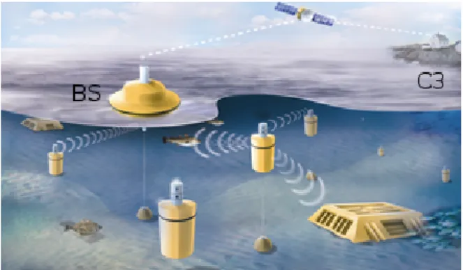
A Static Network (SN) is a network paradigm where: a) nodes are well known before the network deployment, b) the number of nodes is constant. An example of SN is the Underwater Acoustic Network (UAN), which is a network paradigm allowing communi-cation among underwater nodes equipped with acoustic modems. A UAN can be used for many purposes such as ocean sampling, en-vironment monitoring, undersea explorations, tactical surveillance and disaster prevention. Figure 2.1 shows an example of a UAN. The Figure shows a Base Station (BS), able to communicate both with a Command and Control Centre (C3), located in the land, and many underwater acoustic nodes.
1.4. STATIC NETWORKS 21
Figure 1.1: A UAN.
1.4.1
Security Requirements
Due to its nature, generally a SN is an infrastructured network. The presence of an infrastructure allows the nodes to efficiently communicate and exchange information.
In order to guarantee the secure cooperation among nodes, the infrastructure can be exploited. For example, there could be a central base station playing the role of authenticating all the nodes of the network or acting as a Watchdog for the network. This means that it is not needed that nodes are equipped with additional hardware in order to support secure cooperation, although each node could be equipped with a TPM.
In order to exchange messages with the base station (e.g. for the authentication), the software of each node must be extended with algorithms and protocols supporting that.
1.4.2
Attacks E↵ects
Let us assume that the network has a mechanism which authen-ticates all the nodes. Since the nodes are well known before the network deployment and there is a mechanism for nodes authenti-cation, for an attacker it is difficult to add himself to the network as an additional node. This means that he can act only in the fol-lowing ways: a) as an external attacker, b) compromise an existing node.
22 CHAPTER 1. INTRODUCTION In the first case, he has access only to the communication, but not to the nodes. However, if the messages are protected through a cryptographic suite guaranteeing integrity and confidentiality of messages, the attacker cannot perform the external attack.
In the second case, the attacker must be sufficiently equipped in order to compromise an existing node. Once compromised a node, the attacker has full access to the information it stores (e.g. encryption and authentication keys). The e↵ects of this attack could be very destructive, because the attacker can send bogus messages, modify the existing ones or behave into an unpredictable way. In order to protect the network from such an attack, an Intrusion Detection System (IDS) [12] can be added to the network. The IDS can be deployed as a part of the infrastructure. It monitors if the nodes behave as expected; if they do not, it excludes them from the network. However, the adversary is able to control the compromised node until the IDS does not discover it. This means that the protection of the network depends on the efficiency of the IDS to discover a compromised node.
1.5
Dynamic Networks
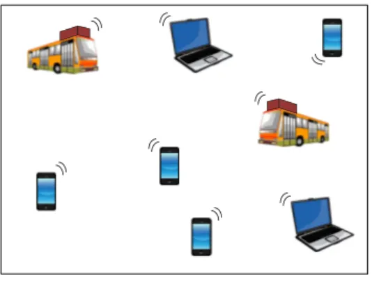
A Dynamic Network (DN) is a network paradigm where: a) nodes change during the network lifetime, b) the number of nodes change during the network lifetime, c) the position of nodes is known only at runtime, d) the nodes are not homogeneous. An example of DN is the Delay Tolerant Network (DTN), which is a network paradigm allowing communication among nodes even in presence of network partitions. Figure 1.2 shows an example of DTN. It is composed of many smartphones, laptops and buses equipped with special routers.
1.5.1
Security Requirements
Generally, a DN does not need an infrastructure, because nodes connect each other by means of the ad-hoc mechanism. However, in some cases the infrastructure is present in order to coordinate
1.5. DYNAMIC NETWORKS 23
Figure 1.2: A DTN. the nodes.
An engineer wanting to design a DN guaranteeing the secure cooperation among nodes should take into account that it does not require an infrastructure natively so that he should not introduce it to the network. A well designed DN, instead, should exploit the network features, such as upgrade the nodes capabilities. For example, each node could be equipped with additional hardware (e.g. TPM), allowing it to verify whether the software stack of the other nodes has been compromised or not. Furthermore, the software a node is equipped with could be extended with additional algorithms and protocols (e.g. a Watchdog), allowing a node to verify whether the other nodes behaves as expected or not.
1.5.2
Attacks E↵ects
Since in a DN the nodes change dynamically during the network lifetime, an attacker can join the network as a standard node. This means that he does not need an additional equipment for example to compromise a node, because it is sufficient that he has a node.
The attacker can launch both an external or internal attack. In the first case, the network can be protected from the attack through a cryptographic suite, guaranteeing both confidentiality and integrity of messages. In the second case, instead, the
at-24 CHAPTER 1. INTRODUCTION
SN DN MN
Infrastructure YES NO YES
Additional Hardware NO YES YES
Additional Software YES YES YES
External Attack message confidentiality
message integrity
TPM IDS
Internal Attack IDS Watchdog TPM
Watchdog
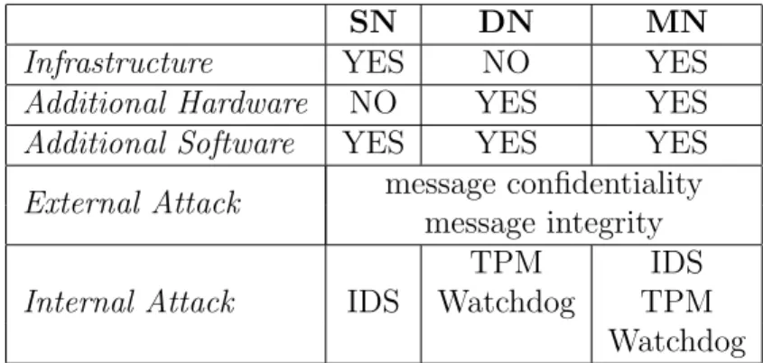
Table 1.1: Comparison of challenging networks requirements and attacks countermeasures.
tack may be destructive, because the malicious node can behave into an unpredictable way. The best solution to this problem is to force each node to be equipped with an additional hardware (i.e. a TPM), which allows all the other nodes to perform a remote attes-tation of the correctness of its software. The TPM should be able to attest that the software has not been altered by the adversary. Furthermore, it should also be able to perform the semantic remote attestation [13].
Another solution to the problem could be extend each node with an additional software (i.e. a Watchdog), which monitors the behavior of the other nodes. If a node does not behave as espected, the Watchdog of all the other nodes, should recognize it and exclude it from the network.
1.6
Mixed Networks
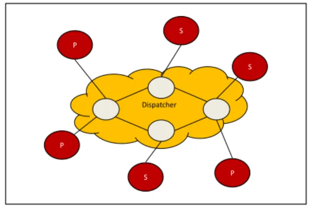
A Mixed Network (MN) is a network paradigm where: a) some nodes do not change during the network lifetime but other nodes do, b) the number of nodes is not constant, c) the position of nodes is known only at runtime, d) the nodes are not homogeneous. An example of MN is the Publish/Subscribe Network (PSN), which is a communication paradigm that supports dynamic, asynchronous, many-to-many communication in a distributed system [3]. In a
1.6. MIXED NETWORKS 25 Dispatcher S S P S P P
Figure 1.3: A Pub/sub network.
PSN a network of brokers is responsible for routing messages from publishers to subscribers. In practice, they act as a dispatcher for the network. Messages are routed based on their topics, an information descriptor contained in the messages themselves. Sub-scribers have to declare their interests in specific topics by issuing subscriptions to brokers. The network of brokers does not change during the network lifetime, while publishers and subscribers change dynamically. Figure 1.3 shows an example of PSN. The nodes in-side the cloud represent the network of brokers, while the other nodes represent the publishers (P) and the subscribers (S).
1.6.1
Security Requirements
A MS is a semi-infrastructured network, in the sense that some nodes communicate through an ad-hoc mechanism, while some others are connected through an infrastructure. For example, in a PSN, the brokers are connected through the ad-hoc mechanism, but at the same time, they act as the infrastructure for the clients of the network.
In order to guarantee the secure cooperation among nodes, a combination of the techniques described for SNs and DNs can be used. In practice, for nodes supported by the infrastructure, the
26 CHAPTER 1. INTRODUCTION mechanisms described for SNs can be exploited, while for nodes not supported by the infrastructure, we can use the mechanisms described for DNs. It is important to notice that the two mech-anisms must be integrated each other in order to avoid that the network is subjected to new vulnerabilities.
1.6.2
Attacks E↵ects
An adversary wanting to perform an attack to a MN, can act in two di↵erent ways: a) attack the infrastructured nodes, b) attack the ad-hoc nodes. In the first case, the attacker can perform one of the attacks described in Section 1.4.2, while in the second case he can perform one the attacks described in Section 1.5.2.
In the case of the PSN, if the attacker breaks the network of brokers (i.e. performs an attack against the ad-hoc nodes), then he has broken the infrastructure too.
1.7
Discussion
In this section we resume the previous described CNs according to the evaluation criteria described in Section 1.3. Table 1.1 resumes security requirements and attacks countermeasures for each family of CN.
The SNs and MNs are infrastructured, while the DN is not. In order to protect the network from an external attack, all the families must provide message encryption and message integrity. In the case of an internal attack, the best solution for a SN is to extend the infrastructure with an IDS. For a DN the protection against an internal attack can be achieved by equipping each node with additional hardware (i.e. a TPM) or software (i.e. Watch-dog). Finally, a MN can contrast an internal attack by extending the infrastructure with an IDS and by equipping each node with additional hardware (TPM) and software (Watchdog).
1.8. CONCLUSIONS 27
1.8
Conclusions
In this chapter we have presented the problem of secure coopera-tion in CNs. We have classified the CNs in three families: static, dynamic and mixed, according to the type of nodes. We have also shown that the requirements for guaranteeing the secure cooper-ation change according to the nature of the CN. Furthermore we have analyzed the e↵ects of the external and internal attacks on the di↵erent families of CN.
Chapter 2
Underwater Acoustic
Networks
Chi lavora con le mani `e un operaio,
chi lavora con le mani e la testa `e un artigiano, chi lavora con le mani, la testa e il cuore `e un artista.
Francesco d’Assisi (1182–1226)
2.1
Introduction
An Underwater Acoustic Network (UAN) is a network paradigm al-lowing communication among acoustic underwater nodes. A UAN can be used for many purposes such as ocean sampling, environ-ment monitoring, undersea explorations, tactical surveillance and disaster prevention.
The communication among the underwater nodes is made pos-sible by exploiting the acoustic modems which nodes are equipped with. Since the acoustic channel is an open medium, an attacker conveniently equipped could intercept the messages traversing the network. This could be very dangerous in a tactical surveillance network where messages must be secret. Furthermore, the attacker could also modify or inject fake messages in the network. This could compromise the correctness of data used for the environ-ment monitoring. All these considerations show the urgency of
30 CHAPTER 2. UNDERWATER ACOUSTIC NETWORKS protecting the underwater acoustic channel and establish a secure channel among the underwater nodes.
The problem of secure cooperation among underwater nodes has been investigated in [14], in which the author presents a sur-vey of vulnerabilities and security requirements of a UAN. Aky-ildiz et al. in [15] also present a survey on research challenges for UANs, including security requirements. They think that the best solution for protecting a UAN is a cross layer approach, in which security traverses all the layers. Dong et al. in [16] make a tax-onomy of the attacks against a UAN. They classify the attacks into three categories: a) physical attacks against nodes, b) attacks against the network, c) attacks against the protocols. They give some guidelines to contrast such attacks, but they do not propose any concrete solution. The same authors in [17, 18] propose some mechanisms for nodes re-organizations, when one or more nodes get destroyed. However, at the best of our knowledge, there is not any work proposing a concrete architecture providing a secure cooperation among underwater acoustic nodes.
In this paper we focus on the problem of secure cooperation of a team of underwater acoustic nodes within surveillance appli-cations and we propose an architecture guaranteeing the secure cooperation among the nodes. The main mission goal is that of protecting an asset (e.g. a critical infrastructure such as a power plant placed on the shore or directly in the water) using detection sonars mounted on each node. We assume that nodes cooperate according to the cooperation algorithm described in [19].
In order to provide a secure communication among nodes, we propose a cryptographic suite which takes into account the pecu-liarities of the underwater channel. With respect to a terrestrial network, in a UAN communication bandwidth is limited, propaga-tion delays are very long, and underwater nodes have limited energy resources as they are battery operated. It follows that standard cryptographic protocols adopted for terrestrial networks must be revisited for the underwater environment. Traditional techniques such as ciphers, digests and digital signatures make message expand so introducing an amount of overhead that is often comparable to or, even, larger than the payload itself. For these reasons, we
pro-2.1. INTRODUCTION 31 pose the use of a cryptographic suite that protects the communica-tion among nodes while keeping at minimum message expansion. The cryptographic suite has been tested during real experiments made in the sea.
We propose two architectures employing the cryptographic suite: a) a short-medium scale system, in which all the nodes are into a unique broadcast domain, b) a large scale system, in which many broadcast domains exist. In the first case, the cryptographic suite maps directly to the data link layer, while in the second case a routing protocol is needed in order to provide multihop. As rout-ing protocol, we use FLOOD [20], a routrout-ing protocol for UANs. FLOOD consists in two phases: the network discovery and the network reconfiguration. During the network discovery phase each vehicle, fixed or mobile, discovers its neighbors and routing tables are built, while during the network reconfiguration phase a mobile vehicle moves. Before starting to move, a mobile node temporarily leaves the system. While moving, a mobile node is not reachable by the other node. When the mobile node reaches its new desti-nation, it joins again the system. The network discovery phase is executed only once, when the system is deployed, while the network reconfiguration phase is executed whenever a mobile node moves.
The network discovery phase of FLOOD is subjected to the spoofing-based Denial of Service (DoS) attack, in the sense that an attacker can continuously trigger the discovery phase of FLOOD and never terminate it. In this paper we extend FLOOD with the cryptographic suite and with a mechanism acting against the spoofing-based DoS attack. The resulting protocol is called Se-FLOOD. In SeFLOOD, every node discovers and authenticates its neighbors and oganizes them in a cluster by distributing them a cluster key. Once clusters have been built, routes can be securely established as in FLOOD. Furthermore, mobile nodes are authen-ticated before adding to the network.
The chapter is organized as follows. Section 2.2 describes the system model, while Section 2.3 the threat model. In Sections 2.4 we describe our cryptographic suite. Section 2.5 describes the short-medium scale. In Section 2.6 we describe the large scale system with reference to FLOOD (Section 2.6.1) and SeFLOOD
32 CHAPTER 2. UNDERWATER ACOUSTIC NETWORKS (Section 2.6.2). Section 2.7 describes the security analysis. Finally in Section 2.8 we give our conclusions and future work.
2.2
System Model
We consider an underwater acoustic surveillance network aimed at protecting a critical asset by means of a set of underwater nodes. The main task of the network is to detect the presence of physical underwater intruders. The research presented has been carried out in the framework of the European project “Underwater Acoustic Network” (UAN) [1].
From a logical point of view, we consider a system composed of a networked set of underwater nodes, each equipped with sensing, computing and acoustic communication facilities. Every underwa-ter node has computational resources comparable to those of a low-budget personal computer—e.g.,. an Intel Atom processor (also for power saving) or a PC104 embedded standard computer—and it is able to run a commodity operating system such as Windows XP or Linux. However, underwater nodes are battery operated and thus have limited energy resources.
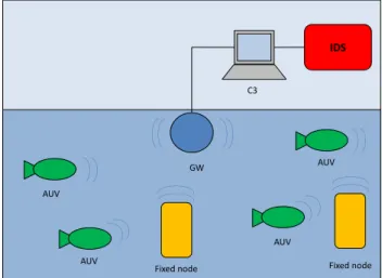
Every node is equipped with a number of sensors that allows it to sense both the state of surrounding sea and the presence of a possible target in the neighbourhood. Of course, a node may only achieve a local partial view of the system. For this reason, a number of underwater nodes are deployed around the critical asset and each of them reports the sensed data to a Command and Control Center (C3) station. Such a station collects sensed data from underwater nodes, achieves a global view of the system, and performs an intrusion detection algorithm.
Nodes may be both fixed and mobile. Mobile underwater nodes are unmanned and for this reason we call them autonomous un-derwater vehicles (AUVs). AUVs are crucial components in the surveillance system. The surveillance system strives to cover the largest connected area. Due to the changing sea conditions, fixed nodes alone would be hardly able to guarantee this requirement all the time. For this reason, the system employs AUVs that
dynam-2.2. SYSTEM MODEL 33 AUV AUV Fixed node C3 GW AUV AUV IDS Fixed node
Figure 2.1: The surveillance network.
ically change their position in order to fulfil the requirement [19]. AUVs move to locations in response to specific commands from the C3 station. Upon reaching its target location, an AUV dynami-cally adjusts its position according to the changed sea conditions in order to both maintain communication connectivity with the other AUVs and guarantee the largest connected detection area.
From the logical model, we can derive two di↵erent communica-tion models that the surveillance system has to support. One model is a point-to-point communication model between and underwa-ter node and the C3. The other is a one-to-many communication model between AUVs. Given the peculiarities of an underwater communication system, we support these models by means of the network architecture depicted in Figure 2.1. The gateway (GW) is a powerful underwater acoustic node, located under the asset, equipped both with a radio antenna, emerging from the water and an acoustic modem. It communicates with the C3 through the ra-dio antenna and with the underwater nodes through the acoustic modem. In practice, the GW acts as a gateway between the C3 and the underwater nodes. Although the GW is located in the sea, it is not energy-constrained because it is connected to the asset through a power cable.
34 CHAPTER 2. UNDERWATER ACOUSTIC NETWORKS
AUV AUV Fixed nodes C3 GW
1
2
(a)
AUV AUV Fixed nodes C3 GW
2
1
(b)
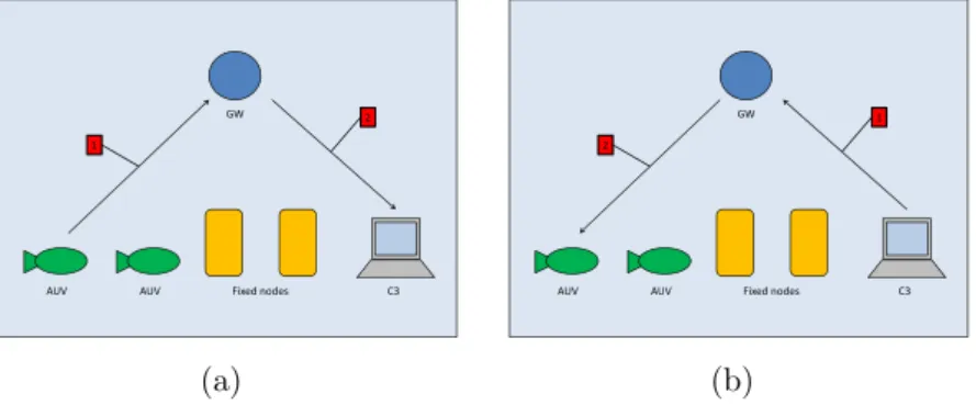
Figure 2.2: The point-to-point communication model.
AUV AUV Fixed node C3 GW
1 2
AUV AUV
Figure 2.3: The one-to-many communication model.
Figure 2.2 shows how the point-to-point communication model is supported by the UAN network architecture. The point-to-point communication can be of two types: a) from the node to the C3, b) from the C3 to an AUV. In the first case (Figure 2.2 a), a node reports sensed information or other useful information (e.g. its position) to the C3. In order to achieve that, it sends the message to the GW (1), which relays it to the C3 (2). In the second case (Figure 2.2 b), the C3 sends a command to an AUV (e.g. move from a specific location to another of the area). In order to achieve that, the C3 sends the message to the GW (1), which relays it to the AUV (2).
Figure 2.3 shows how the one-to-many communication model is supported by the UAN network architecture. In order to send a message to the other AUVs, AUVs could exploit the broadcast
2.3. THREAT MODEL 35 underwater acoustic medium, an thus broadcast a message with sufficient energy to reach all the AUVs, as needed. However, the necessary power would be very large and thus AUVs would drain their battery quickly. As the power needed to send a message de-cays with powers greater than two of the distance [15, 21], direct link communication between AUVs may not be the most energy efficient solution. For this reason, we assume that when an AUV wants to broadcast a message, it sends the message to the GW (message 1 in the Figure 2.3), which acts as a relay for the mes-sage and broadcasts it to the other AUVs (mesmes-sage 2 in the same Figure). The GW can broadcast the message using all the power it is necessary, because it is not resource constrained.
The above communication models can be implemented in un-derwater environments having di↵erent geographical sizes. We con-sider small-medium scale a system composed of a single underwater acoustic broadcast domain, and large scale one which instead re-quires a multi-hop network. In the former case, the logical model of communication maps directly to the real structure of the net-work and there is no need for a routing protocol, while in the latter case a routing protocol is needed. In this paper we focus on FLOOD [20], a routing protocol for underwater acoustic net-works. FLOOD builds a tree according to the Dijkstra algorithm with the GW as root. Then, unicast and multicast messages are routed along the tree.
2.3
Threat Model
The described application scenario may be subjected to several threats and attacks [5]. We assume that the adversary, equipped with an acoustic modem, has full access to communication. Fur-thermore we assume that when the network is deployed, it is not compromised. However, after the network deploying, the adversary can compromise a node.
In particular, we assume that the adversary can perform the following attacks:
imper-36 CHAPTER 2. UNDERWATER ACOUSTIC NETWORKS sonates an existing node by injecting wrong measures, statis-tics or wrong routing information. This could lead to the production of wrong routing tables or wrong results, which potentially can be dangerous,
• spoofing-based Denial of Service (DoS) attacks [22]. The ad-versary can impersonate an existing node and compromize the network integrity with the aim of reducing the network availability. This attack is particularly dangerous because it is difficult to distinguish it from the standard protocol exe-cution,
• node compromision. The adversary can compromise a node, accessing to all the information contained in it.
2.4
The Cryptographic Suite
In order to protect the system from the spoofing-based attack against integrity, we organize the GW and the nodes in order to form a secure group G. Each node ni belonging to the group shares a link key Kig with the GW. This key is used to secure the communica-tion between the GW and each node. Furthermore, all the nodes and the GW share a group key Kg which is used to secure the broadcast messages sent by the GW to all the nodes.
In the remainder of the section, we describe a cryptographic suite providing confidentiality, authenticity of messages and a key management protocol to distribute a new key whenever needed. Implementing these services in a UAN is challenging due to the severe limitations of the networking environment in terms of very high message propagation delay, very low bandwidth, and high energy consumption for communication. Limitation in the message size is hence of paramount importance in order to reduce battery consumption in AUVs.
2.4. THE CRYPTOGRAPHIC SUITE 37
2.4.1
Confidentiality
Confidentiality of messages is achieved by encrypting messages. In this paper we use the symmetric encryption technique. Encryption is achieved by splitting cleartext in blocks of fixed, predefined bit-length and encrypting each single block. In the most general case, cleartext length is not multiple of the block length. Thus padding is necessary. However, padding has the negative e↵ect that the ci-phertext may result up to one block longer than the corresponding cleartext. This e↵ect is called ciphertext expansion. While cipher-text expansion is negligible in a traditional network, it becomes relevant in wireless sensor networks and, in particular, underwater acoustic networks. In these networks, communication and energy limitations require to keep a message size small and ciphertext ex-pansion may introduce an overhead that is not negligible anymore. In order to completely avoid the ciphertext expansion problem, we use the CipherText Stealing (CTS) technique that alters the pro-cessing of the last two blocks of plaintext, resulting in a reordered transmission of the last two blocks of ciphertext and no ciphertext expansion [23].
2.4.2
Authenticity
Encryption without authentication is insecure [24]. For example, an adversary may flip bits in unauthenticated ciphertext and cause predictable changes in the plaintext that receivers are not able to detect. To address this vulnerability, the system always authen-ticates messages. Security of hash functions is directly related to the length of the digest. However, as a digest is appended to the message, it becomes another source of message expansion and con-sequent communication overhead. UAN features a trade-o↵ be-tween security and performance by using 4 bytes digests resulting from truncating the real hash function value. Using such a short hash function value is not detrimental to security [25]. An adver-sary has 1 in 232 chances to blindly forge a digest. If an adversary repeatedly tries to forge it, he/she needs at maximum 231 trials. However, the adversary cannot perform trials o↵-line. This means
38 CHAPTER 2. UNDERWATER ACOUSTIC NETWORKS
K(n) K(n-1) K(i) K(1) K(0)
K(i-1)= h(K(i)), i = n,…,1
revealed creation
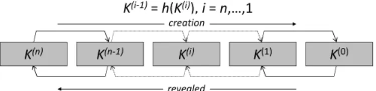
Figure 2.4: Key Chain.
that the adversary has to validate a given forgery only by sending it to an authorized receiver. This implies that the adversary has to send 231 messages in order to successfully forge a single mali-cious message. In a conventional network this number of trials is not large enough. However, in a underwater acoustic network this may provide an adequate level of security. An adversary can try to flood the network with forgeries, but on a 500 bps channel with 184-bit messages, he/she can only send about 2.71 attempts for sec-ond. Thus, sending 231 messages requires around 306 months, i.e., about 25 years. Battery-operated vehicles have not enough energy to receive that many messages. Furthermore, the integrity attack would translate into a denial of service attack since the adversary needs to occupy the acoustic channel for a long time. Fortunately, it is feasible to detect when such a attack is underway. UAN uses a simple heuristic: vehicles could signal the base station when the rate of digest/MAC failures exceeds some predetermined threshold.
2.4.3
Group Key Management
Each time a node leaves the system, the GW generates and dis-tributes a new group key Kg. This is done to avoid that an old node is able to read new messages. As to rekeying protocol, we choose S2RP, a secure and scalable rekeying protocol for resource-constrained devices [26]. S2RP is particularly suitable for UAN for two reasons. First of all, S2RP provides a very efficient proof of key authenticity. Actually, S2RP verifies the authenticity of a key by computing a hash function. So, verification is very
com-2.4. THE CRYPTOGRAPHIC SUITE 39 puting efficient and does not require any additional information, e.g., MACs or digital signatures, which would cause message ex-pansion. Secondly, S2RP requires a number of rekeying messages that is logarithmic in the number of nodes so making the key dis-tribution phase highly scalable. In short, the key authentication mechanism levers on key-chain, a technique based on the Lamport one-time passwords. A key-chain is a set of symmetric keys so that each key is the hash pre-image of the previous one (see Figure 2.4). Hence, given a key K(i) in the key-chain, anybody can compute all the previous keys K(j), j i, however nobody, but the key-chain creator, can compute any of the next keys K(j), j > i. Keys are revealed in the reversed order with respect to creation order. Given an authenticated key in the key-chain, anybody can authenticate the next revealed keys by simply applying an hash function. For example, if K(i)is an authenticated key, than anyone can verify the authenticity of K(i+1)by verifying that K(i) = h(K(i+1)). To reduce the communication overhead, the GW maintains a logical key tree (see Figure 2.5) each internal node contains a key-chain, whereas each leaf is associated with a node and contains the node-key, i.e., the secret key that the node shares with GW. We call current key of a key-chain the last revealed key of the key-chain and next key the hash pre-image of that key. Furthermore, we denote by Ki and Ki+ respectively the current and next key of the key-chain associated to tree node i. Notice that Ki = h(Ki+). Each node maintains a key-ring that contains every key Ki such that the sub-tree rooted at node i contains the leaf associated with the node-key. Hence, with reference to Figure 2.5, the key-ring of node v4 is K1, K2, K5. As it turns out, key K1, associated to the key tree root, is shared by all nodes and acts as the group-key. Let us now suppose that node v4 leaves the group. All keys in its key ring are considered compromised and KMS has to broadcast the respective next keys K1+, K2+, K5+ by means of the following rekeying messages:
1. GW ! n3: EKv3(K5+) 2. GW ! n3: EK5+(K2+) 3. GW ! n1, n2: EK4(K
+ 2)
40 CHAPTER 2. UNDERWATER ACOUSTIC NETWORKS K1 K2 K3 K2 K3 K4 K5 K6 K7 n1 n2 n3 n4 n5 n6 n7 n8
Figure 2.5: Key Tree. 4. GW ! n1, n2, n3: EK2+(K1+)
5. GW ! n5, n6, n7, n8: EK3(K + 1 )
Upon receiving a rekeying message, after it has been properly decrypted, the authenticity of the next key therein contained is verified by computing its hash and comparing the result to the corresponding current key. For instance, upon receiving rekeying message 5, n6 decrypts the message by means of K3 and verifies the authenticity of K1+ by ascertaining that K1 = h(K1+). As it turns out the rekeying protocol requires O(logNn) rekeying mes-sages, where Nn is the number of nodes. Furthermore, given the key-chain authentication mechanism, every rekeying message needs to carry only the next key (in its encrypted format). No additional information proving key authenticity is thus required. Notice that this is a great advantage in terms of communication overhead with respect to using digital signatures, for example. Let us suppose that group keys are 128-bit long and we use ECC-180 digital sig-nature to authenticate them. ECC-180 is nowadays considered as secure as RSA-1024. In ECC-180 a digital signature is 360 bits and thus a rekeying message would be 488bits, i.e., 3.8125 times longer than in the approach proposed here.
2.4. THE CRYPTOGRAPHIC SUITE 41 FLG1 C3 GW FLG2 FN2 FN1
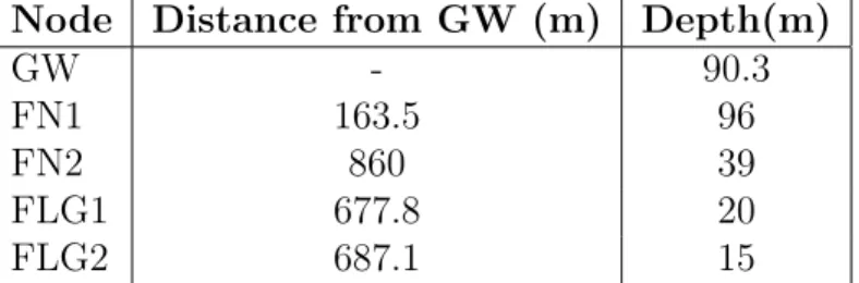
Figure 2.6: The tested scenario.
Node Distance from GW (m) Depth(m)
GW - 90.3
FN1 163.5 96
FN2 860 39
FLG1 677.8 20
FLG2 687.1 15
Table 2.1: Configuration parameters for Scenario L.
2.4.4
Experimental tests
In this section we analyze performance of our system through ex-perimental tests. We have performed exex-perimental tests during the UAN experiments performed on May 2011 in Norway. For ma-jor details about water conditions, winds, temperatures and so on, please see [1]. Figure 2.6 shows the topology of the network which has been tested during the experiments. There are the GW, two fixed nodes (FN1 and FN2), but the FN1 is only a relay node. The network is composed also of two mobile nodes (FLG1 and FLG2). As mobile nodes, we have used the Folaga, deployed by GraalTech [27].
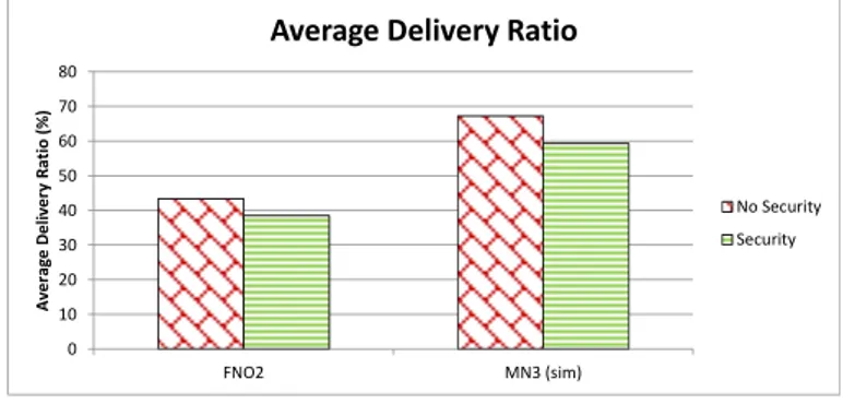
42 CHAPTER 2. UNDERWATER ACOUSTIC NETWORKS 0 10 20 30 40 50 60 70 80 FNO2 MN3 (sim) Av e ra ge D e liv e ry R at io ( % )
Average Delivery Ratio
No Security Security
Figure 2.7: Average Delivery Ratio with security and without se-curity.
placed at a depth of 96m, while FN1 and FN2 at a depth of 96m and 39m, respectively, with a distance from the GW of 163.5m and 860m respectively. The nodes FLG1 and FLG2 are placed at a depth of 20m and 15m respectively, with an initial position of 677.8m and 687.1m far from the GW, respectively.
We have measured the Average Delivery Ratio (ADR), in order to verify whether the nodes are still able to communicate even in presence of the overhead added by security. The ADR is the average ratio between the number of received messages and the number of sent messages, both calculated at the application layer. In practice, it measures the fraction of messages the network is able to deliver. Ideally the delivery ratio should be equal to 1. The ADR has been tested with the cryptographic suite enabled (C-ON) and disabled (C-OFF).
Figure 2.7 shows the ADR of nodes FN2 and FLG2. The other nodes are not shown because of lack of data. We note that the ADR without security is greater than that with security in both nodes. We can explain this in the following way. Each message is associated a CRC, which is calculated at the data link layer. When the CRC verification fails, the message is dropped. Furthermore, when the message size increases, also the packet loss for that mes-sage increases so that the probability that the mesmes-sage is corrupted and dropped increases. When the security is enabled, the message
2.5. SMALL-MEDIUM SCALE SYSTEM 43 size is increased of 4 bytes (due to the digest appended to the mes-sage) with respect to the message without security. This causes the ADR increase when the security is enabled.
2.5
Small-medium scale system
The small-medium scale system is given when all the nodes fall into a unique broadcast domain. In this case a routing layer is not needed so that the logical models described in section 2.2 can be mapped directly to the data link layer. Both the GW and the nodes can send their messages by exploiting the broadcast acoustic channel. Since the messages sent from a node to the GW should be unicast, but the medium is broadcast, we protect such messages through the cryptographic suite described in section 2.4.
2.6
Large Scale System
The large scale system is given when all the nodes do not fall into a unique broadcast domain so that a multihop network is needed. As routing protocol we use FLOOD [20]. FLOOD has the advan-tage that has been developed and tested in a real UAN. However, it does not provide any mechanism to protect messages from the attacks described in section 2.3. For this reason, we extend it with the cryptographic suite described in section 2.4. In practice, each message exchanged to build routing tables or containing data is en-crypted and authenticated through the cryptographic suite. The resulting protocol is called SeFLOOD.
In its original version, the FLOOD protocol does not support the broadcast communication. In order to support the key distri-bution, we map the S2RP protocol to FLOOD by using the relay mechanism: each message is sent only once on a given communica-tion link. Assume that we have a network with the topology shown in Figure 2.8 and the key three for this topology is that shown in Figure 2.5. Furthermore, assume that the node n4 leaves the net-work. In this case the keys K1, K2 and K5 must be renewed. The key K1 must be sent to all the nodes. The GW sends it to n1
44 CHAPTER 2. UNDERWATER ACOUSTIC NETWORKS GW n3 n2 n1 n8 n7 n6 n5 n4
Figure 2.8: An example of topology.
and n5. Then n1 and n5 relay it to n2 and n6 and n7 respectively. Finally, n2 and n7 relay it to n3 and n8, respectively. The key K2 must be sent to n1, n2 and n3, while the key K5 must be sent only to n3. As the messages containing the keys K2 and K5 must follow the same path, they can be aggregated so that the GW sends the aggregated message to n1, which relays it to n2, which relays it to n3.
The relay mechanism can be used also when a node wants to broadcast a message to the other nodes (one-to-many communica-tion model). It firstly sends it to the GW, which relays it to the other nodes. The point-to-point communication model, instead, can exploit the sandard unicast routing mechanism supported by FLOOD.
In the remainder of the section we describe firstly FLOOD, then SeFLOOD and finally we compare them through simulation performance analysis.
2.6.1
FLOOD
During the network discovery phase, the FLOOD protocol is based on the flooding principle. The protocol relies on the idea that a node broadcasts a received message until it receives the same
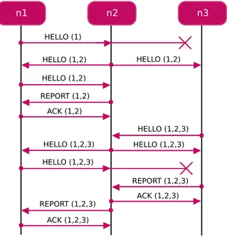
mes-2.6. LARGE SCALE SYSTEM 45 sage it has sent. Figure 2.9 shows an execution instance of the FLOOD protocol. Suppose that the network is composed of three nodes. Furthermore, suppose that the transmission range of the GW (n1) covers only the node n2, but the node n2 is able to reach both n1 and n3. Node n3 is able to reach only n2. The protocol is initiated by the GW which broadcasts a HELLO(n1), including its identifier and the time ti at which the message is sent. Upon receiv-ing the hello message, the node n2 adds to the message its identifier and other information, including the quality of the link (e.g. sig-nal attenuation). Then n2 relays the messasge HELLO(n1,n2) by broadcasting it after a randomized delay. When n1 receives the message, it re-broadcasts it. When n2 receives the new message, it sends to n1 a REPORT(n1,n2) unicast message. The GW acknowl-edges n2 by sending it a ACK(n1,n2) unicast message. With the ack message, the protocol between n1 and n2 is completed. However, also the node n3 receives the HELLO(n1,n2) message. Suppose that n3 receives it after that n2 receives ACK(n1,n2). The node n3 adds to the message its identifier and information about link quality. Then it broadcasts HELLO(n1,n2,n3). Upon receiving this message, the node n2 re-broadcasts it. The message is received both by the GW n1 and the node n3. Upon receiving the message, the node n3 builds a report message REPORT(n1,n2,n3). When n2 receives the report message from n3, it sends it the ACK(n1,n2,n3) unicast message so that the protocol between n2 and n3is complete. When the GW receives the message HELLO(n1,n2,n3) it re-broadcasts it. Upon receiving the message the node n2 builds a report message REPORT(n1,n2,n3). When n1 receives the report message from n2, it sends it the ACK(n1,n2,n3) unicast message so that the protocol between n1 and n2 is complete.
Network Reconfiguration
When the network discovery phase is completed, FLOOD allows the network to dynamically reconfigure. In order to support the network reconfiguration phase, it makes the following assumptions: a) each mobile node knows when it is going to move and when it has reached its new location; b) each mobile node does not send/receive
46 CHAPTER 2. UNDERWATER ACOUSTIC NETWORKS
2.6. LARGE SCALE SYSTEM 47
Figure 2.10: A DoS attack. messages while moving.
Before starting to move, a mobile node nm sends a DEL(nm) message to the GW in order to be removed from the routing tables. Upon receiving the message, the GW updates routing tables by considering only the remaining nodes. Then the GW sends a BEST message to each node for which the routing table is changed. The BEST message is unicast. The message includes also information about the new next hop to reach the GW.
Assume now that the mobile node has reached its new loca-tion so that it broadcasts an ADD(nm) message. Upon receiving the ADD(nm) message, each node sends back it a ADD-ACK mes-sage containing information about link quality. The mobile node acknowledges all the received ADD-ACK messages by sending back unicast ADD-ACK messages, containing information about link qual-ity. Finally, the mobile node sends an ADD-REPORT message to the GW so that the GW can update the routing table and distribute to all the interested nodes the new table by sending a ADD-BEST message.
48 CHAPTER 2. UNDERWATER ACOUSTIC NETWORKS The spoofing-based DoS attack
The FLOOD protocol is subjected to the spoofing-based DoS at-tack. Figure 2.10 shows an example of how an attacker can perform a spoofing-based DoS attack in a network composed of three nodes. Whenever the attacker receives a HELLO message, it can add a new fake node and broadcast the message to the other vechicles. In this way the protocol never completes. In order to avoid this kind of attack, each node could be deployed with the list of all the nodes identifiers belonging to the system. Thus, if the attacker tries to add a new fake node to the network, each node rejects it, because the fake node is not contained in that list. However, due to the underwater conditions and to the high distances among nodes, it may happen that a node n1 is not able to directly contact nodes n2 and n3 belonging to the system. The attacker could exploit this situation in order to use n2 and n3 identifier to perform a DoS attack.
2.6.2
SeFLOOD
In order to protect the FLOOD protocol from the threats described in section 3.3.1, we have extended it with the cryptographic suite described in section 2.4. The resulting protocol, SeFLOOD, en-crypts and authenticates all the messages by using the crypto-graphic suite. Furthermore, SeFLOOD extends FLOOD with a mechanism contrasting the DoS attack. This mechanism is based on the Cluster Key Distribution Protocol (CKDP).
In order to improve security, we organize nodes in clusters, such that if an adversary compromises a node, he is able to compromize only the cluster which the node belongs to and not all the network. Each cluster is associated to a Cluster Key, which is used to secure communication among nodes belonging to the same cluster. As the number of nodes in the network is low, all the nodes could be pre-deployed with all the possible Cluster Keys. This will be discussed later in the paper. In the reminder of the section, we firstly describe the CKDP, which dynamically distributes a Cluster Key only to nodes belonging to that cluster. Then we describe a particular
2.6. LARGE SCALE SYSTEM 49 application scenario where the Cluster Keys can be predeployed in the nodes.
The Cluster Key Distribution Protocol
We consider the network as connected graph G = (V, E) with ver-texes V representing nodes and edges E their connections. Each connection has a cost C, given by the channel quality (e.g. signal attenuation). We assume that each pair of nodes (ni, nj), i 6= j in the network shares a key, called Link Key Kij, which is used to protect unicast messages between ni and nj. In order to dis-tribute the link keys, a well known key agreement protocol can be used such as Elliptic curve Diffie-Hellman [28] or the Blundo scheme [29]. However, for simplicity, each node can be deployed with a table, called Link Key Table (LKT), containing all its Link Keys. This solution is indicated for a UAN because the number of nodes is low and each node has enough memory to store all the LKT. For example, with a Link Key of 128 bits and a network of 1024 nodes, the LKT is 16 Kbytes. If we consider that a node is equipped with a memory of 2 GBytes, for a network of 1024 nodes, the LKT wastes only 0.78% of memory.
We split the graph G into N subgraphs G1,G2, ..GN such that each subgraph Gn, 0 n N constitutes a cluster. A cluster is made of a subset of nodes contained into a unique broadcast domain.
In order to securely and efficiently broadcast messages into a cluster, each node ni generates a Cluster Key Ki and distributes it to all the members of its cluster. Thus each node maintains a Cluster Key for each node of the cluster. The Cluster Key Table (CKT) of node ni stores all the Cluster Keys of the members of the cluster which ni belongs to. In general, the number of entries of the CKT is less than the number of entries of the LKT. However if all the nodes fall into a unique broadcast domain, the number of entries in CKT is equal to that of LKT. This means that also the memory wasted by CKT is negligible.
In order to distribute all the Cluster Keys, the following Cluster Key Distribution protocol is executed:
50 CHAPTER 2. UNDERWATER ACOUSTIC NETWORKS
Figure 2.11: The CKDP applied to FLOOD. 1. ni ! ⇤ : ni, Ti
2. nj ! ni : nj, EKij(Kj, Ti)
The protocol is composed of two phases, the discovery phase (1) and the key distribution phase (2). During the discovery phase each node ni generates a fresh quantity Ti and broadcasts it together with its identifier ni. Upon receiving the message (1), each node nj sends niits cluster key Kj, its identifier nj and the fresh quantity nj, all encrypted with the key Kij (2). Upon receiving the message from nj, the node ni verifies its freshness and stores the received cluster key Kj.
The CKDP is executed before FLOOD, in order to allow only authorized nodes to trigger the FLOOD protocol. In fact, an ad-versary performing the DoS attack can only replay the first message of the protocol, but he cannot trigger all the FLOOD protocol.
2.6. LARGE SCALE SYSTEM 51 Figure 2.11 shows an instance of CKDP. Assume that the net-work is composed of three nodes, the GW n1 and the nodes n2 and n3. Furthermore, suppose that the transmission range of n1 covers only the node n2, but the node n2 is able to reach both n1 and n3. node n3 is able to reach only n2. Each node broadcasts its identi-fier and a fresh quantity. As the medium access is CSMA like, a single node per time can transmit. Assume that at the beginning the node n1 broadcasts the message [n1, T1]. Upon receiving the message, the node n2 encrypts its cluster key K2 and the received T1 with the link key K12. Then n2 appends to the message its iden-tifier n2 and sends the message back to n1. As the medium is not busy, the node n2 now can broadcast the message [n2, T2]. Both n1 and n3 receive it so that they can encrypt their cluster keys, K1 and K3 respectively and the fresh quantity T2, received from n2 with the link ley K12 and K13 respectively. Finally they send the message back to n2, specifying also their identifier. Eventually, n3 broadcasts the message [n3, T3]. Upon receiving it, n2 encrypts the fresh quantity T3 and cluster key K2, with the link key K23, and sends the message back to n3. At the end of the protocol three clusters are built, C1 = (n1, n2), C2 = (n1, n2, n3), C3 = (n2, n3) with cluster keys K1, K2 and K3, respectively.
Secure Network Reconfiguration
SeFLOOD supports also mobile nodes, without adding overhead in terms of number of messages. In fact it exploits FLOOD messages sent by a mobile node in order to distribute the cluster keys. We assume that nodes have loosely synchronized clocks. This hypotesis is reasonable because the system is centralized so that the master can periodically send a synchronization messages to all the nodes of the network.
Assume that nm is a mobile node. If nm wants to delete from the network, it triggers the following protocol:
1. nm ! GW : DEL, nm, Tm, Egm(Tm, nm) 2. GW ! ni: BEST, Egi(Tg, nm)
52 CHAPTER 2. UNDERWATER ACOUSTIC NETWORKS Firstly, nm generates a fresh quantity Tm and encrypts it and its identifier nm with the Link Key Kgm. Then it sends the GW the message (1), containing the previous authenticated Tm, its identi-fier nm and the request to be deleted from the network (DEL). Upon receiving the message (1), the GW , deletes nm from the routing tables, updates the routing tables, generates a fresh quantity Tg and informs every node ni which the routing table must be up-dated for, by sending it the unicast message (2). The message (2) contains the FLOOD BEST message, the identifier of node nm and the fresh quantity Tg, both encrypted with the link key Kgi, shared by the GW and ni. Upon receiving the message (2), each node ni updates its routing table.
Assume now that the mobile node nm wants to add again the network. The node nm triggers the following protocol:
1. nm ! ⇤: ADD, nm, Tm
2. ni ! nm: ADD-ACK, Eim(Tm, Ti, Ki) 3. nm ! ni: ADD-ACK, Eim(Ti, Km)
4. nm ! GW : ADD-REPORT, {E1m(|| < ni, Ti >8ni 2 Cm)} 5. GW ! ni: ADD-BEST Egi(Ti)
At the beginning, the mobile node nmgenerates a fresh quantity Tm and broadcasts the ADD message appending the fresh quantity Tm to it (1). Upon receiving the message (1), every node ni gen-erates a fresh quantity Ti and appends to the ADD-ACK message its cluster key Ki, the fresh quantity Ti and the received Tm, all encrypted with the link key Kim. Finally it sends the obtaneid message to nm (2). When nm receives the message (2) from the node ni, it appends to the ADD-ACK message its cluster key Km and Ti, all encryptedwith the link key Kim. Finally it sends the message to the node ni (3). The node nm sends the message (3) to every node ni which it received the message (2) from. Eventu-ally nm appends to the ADD-REPORT message all the received fresh quantities Ti. The symbol || indicates the append operation. In practice, nm sends to the GW the list of all the fresh quantities Ti
2.6. LARGE SCALE SYSTEM 53 and the nodes ni which it received the message (2), i.e. the nodes belonging to its cluster Cm. Before sending the message (4), nm encrypts all the couples < ni, Ti > with the link key Kgm.
Key Refreshing
Each node ni shares with the GW a key, called Private Key Pi, which is used by the GW to authenticate specific messages sent from the GW to ni. In particular, whenever the GW detects a compromised node nc, it informs all the nodes having nc in their cluster to refresh their Cluster Key and distribute it to all the nodes of the cluster, except for nc. The GW sends to the interested nodes the following unicast REFRESH message:
• GW ! ni: EPj(REFRESH, nc), REFRESH, nc
where nc indicates the node to be excluded from the next key distribution. Once received the REFRESH message, each node ni triggers again the key distribution phase of the CKDP, excluding the node nc.
This Key Refreshing mechanism allows a compromised node to perform attacks only until a new cluster key is distributed. The time it can remain active in the network depends on the capability of the IDS to detect quickly an adversary. However, once detected, the adversary can be easily excluded from the cluster and more in general from the network.
Key Predeployment
In the Section 2.6.2 we have described the CKDP, which allows each node to distribute its Cluster Key to the other nodes belong-ing to its cluster. However, sometimes, it may happen that when the network is deployed, each node is initially located into a well known position so that it knows in advance its potential neighbors. A potential neighbor i for node j is a node which is located in the transmission range of j, but it could be not acoustically reachable by j because of the sea conditions. This means that i and j become
54 CHAPTER 2. UNDERWATER ACOUSTIC NETWORKS e↵ective neighbors only if the conditions of the sea (e.g. tempera-ture, salinity) allow the acoustic communication between the two nodes.
If a node knows in advance its potential neighbors, the first phase of the CKDP (i.e. the discovery phase) can be completely avoided, because a node can assume as neighbors its ppotential neighbors. However, during the key distribution phase, the node is able to recognize its e↵ective neighbors.
Note that the assumption that each node can know in advance its potential neighbors cannot be applied into Wireless Sensor Net-works (WSNs), because, due to the high number of nodes, nodes are randomly deployed in the area. In a UAN, instead, the number of the nodes is low and they can be deployed into a well known position.
2.6.3
Performance evaluation
In order to test how much overhead the security adds to FLOOD, we have compared SeFLOOD with FLOOD by using the SimPy simulator [30]. We have used realistic results obtained during some experimental tests done in sea [1]. They showed that the average Round Trip Time of the network was about 19 sec., while the max-imum transmission rate of the acoustic modems was 500 bits/sec.
We have considered a network composed of 7 fixed nodes, the GW and 1 mobile node. We have split the simulation duration in two phases: the network discovery phase, which is executed when the simulation starts, and the reconfiguration phase, during which the mobile node moves from a point to another of the network. In particular, firstly it deletes from the network and then adds again to it.
We have simulated two scenarios aimed at studying the perfor-mance with di↵erent topologies: a Sparse Scenario and a Dense Scenario. Figure 2.12 shows Sparse Scenario and Dense Scenario respectively. In the Sparse Scenario each fixed node is able to com-municate with 2 neighbors, while in the Dense Scenario each node is able to communicate with 5 neighbors.
2.6. LARGE SCALE SYSTEM 55
Leave Join
M M
GW
(a) Sparse Scenario.
Leave Join
M M
GW
(b) Dense Scenario.