UNIVERSITÀ DI PISA
Scuola di Dottorato in Ingegneria “Leornado da Vinci”
Corso di Dottorato di Ricerca in
INGEGNERIA DELL’INFORMAZIONE
Tesi di Dottorato di Ricerca
Intelligent Network Infrastructures:
New Functional Perspectives on
Leveraging Future Internet Services
Autore:
Luiz Gustavo Zuliani
Relatori:
Prof. Stefano Giordano Prof. Franco Russo
Anno 2011 SSD ING-INF/03
Ai miei genitori Aos meus pais
Sommario
La rete Internet del 21° secolo è molto diversa da quella dei primi anni 80. Essa nel tempo si è adattata, diventando una piattaforma di business di grande successo su scala globale. Come ogni tecnologia di successo, ha subito un processo naturale di ossificazione. Negli ultimi 30 anni, per poter far fronte a nuove applicazioni emergenti si è cercato di aggiungere nuove funzionalità, estendendo i protocolli esistenti, creando reti overlay, oppure ricorrendo all’utilizzo di collegamenti a banda sempre più elevata. Purtroppo, questo approccio non è idoneo per un’ampia gamma di nuove applicazioni che per poter essere utilizzate richiedono alla rete funzionalità cosi avanzate che lo stack TCP/IP e i suoi derivati non possono fornire. A tal proposito, le reti delle prossima generazione (next generation networks, oppure semplicemente NGN) sono pensate proprio per supportare i futuri servizi Internet. Questa tesi contribuisce con tre proposte a questo ambizioso obiettivo.
La prima proposta presenta un’architettura preliminare che permette alle NGN di richiedere in modo trasparente servizi avanzati a livello 1, come per esempio la QoS e i circuiti punto-multipunto. Questa architettura è basata su tecniche di virtualizzazione applicate al livello 1 che mascherano alle NGN tutte le complessità che riguardano la fornitura di circuiti inter-dominio. Sono stati considerati anche gli aspetti economici, rendendo l’architettura appetibile ai carrier.
Il secondo contributo riguarda un framework per lo sviluppo di una rete DiffServ-MPLS basata esclusivamente su software open source e comuni PC. Inoltre, un software router DiffServ-MPLS è stato progettato per consentire la prototipazione di NGN che, come elemento iniziale di sviluppo, fanno uso di pseudo circuiti virtuali e qualità del servizio garantita.
Infine, si propongono algoritmi per il routing e l’assegnamento delle lunghezze d’onda (routing and wavelength assignment) nelle reti fotoniche. Tali algoritmi tengono conto delle restrizioni a livello fisico per garantire al 100% il profilo di QoS richiesto anche in caso di un guasto nella rete. Nuove tecniche sono state introdotte in modo da garantire una probabilità di blocco minore rispetto agli algoritmi che rappresentano lo stato dell’arte, senza tuttavia peggiorare il tempo di setup.
Parole chiave: servizi dell’Internet del futuro, reti di prossima generazione, infrastrutture di rete intelligente, virtualizzazione, reti fotoniche.
Abstract
The Internet experience of the 21st century is by far very different from that of the early ’80s. The Internet has adapted itself to become what it really is today, a very successful business platform of global scale. As every highly successful technology, the Internet has suffered from a natural process of ossification. Over the last 30 years, the technical solutions adopted to leverage emerging applications can be divided in two categories. First, the addition of new functionalities either patching existing protocols or adding new upper layers. Second, accommodating traffic grow with higher bandwidth links. Unfortunately, this approach is not suitable to provide the proper ground for a wide gamma of new applications. To be deployed, these future Internet applications require from the network layer advanced capabilities that the TCP/IP stack and its derived protocols can not provide by design in a robust, scalable fashion. NGNs (Next Generation Networks) on top of intelligent telecommunication infrastructures are being envisioned to support future Internet Services. This thesis contributes with three proposals to achieve this ambitious goal.
The first proposal presents a preliminary architecture to allow NGNs to seamlessly request advanced services from layer 1 transport networks, such as QoS guaranteed point-to-multipoint circuits. This architecture is based on virtualization techniques applied to layer 1 networks, and hides from NGNs all complexities of interdomain provisioning. Moreover, the economic aspects involved were also considered, making the architecture attractive to carriers. The second contribution regards a framework to develop DiffServ-MPLS capable networks based exclusively on open source software and commodity PCs. The developed DiffServ-MPLS flexible software router was designed to allow NGN prototyping, that make use of pseudo virtual circuits and assured QoS as a starting point of development.
The third proposal presents a state of the art routing and wavelength assignment algorithm for photonic networks. This algorithm considers physical layer impairments to 100% guarantee the requested QoS profile, even in case of single network failures. A number of novel techniques were applied to offer lower blocking probability when compared with recent proposed algorithms, without impacting on setup delay time.
Keywords: future Internet services, next generation networks, intelligent network infrastructures, virtualization, photonic networks.
Ringraziamenti
Vorrei esprimere la mia piena gratitudine:
Ai miei tutori Prof. Stefano Giordano e Prof. Franco Russo, per l’orientamento e le opportunità concessemi.
All’Ing. Davide Adami, con il quale ho avuto la fortuna di lavorare da vicino sin dall’inizio. Sempre disposto a darmi una mano, anche sugli argomenti al di là della ricerca. Senza i suoi numerosi contributi, questa tesi non sarebbe stata possibile. Più di un collega d’ufficio, un caro amico.
Al Prof. Michele Pagano e all’Ing. Rosario Garroppo, per i numerosi consigli, suggerimenti e aiuti vari.
A tutti i miei colleghi di dipartimento, in particolare agli amici Gianni Antichi e Davide Iacono con i quali è stato un piacere lavorare nel corso di questi anni. Ai miei tesisti Enrico Gloria, Gianluca Epifano, Luigi Li Calzi e Marcello Gollinucci. Spero che il nostro periodo di collaborazione sia stato per voi proficuo come lo è stato per me.
Ai dipendenti della Portineria e della Segreteria del dipartimento, in special modo a Simone Kovatz, Maura Pancanti, Donatella Giorgi e Rosana Le Rose: siete stati sempre pazienti e gentilissime, perfino quando le mie domande erano già troppe. Alla mia famiglia, per il supporto illimitato e incondizionato.
Al Cav. Walter Ricciluca la cui serietà e integrità costituiscono un riferimento costante per me.
Contents
List of Figures XIII
List of Tables XV
Papers Published by the Author XVII
1 Introduction 1 1.1 Motivations . . . 5 1.2 Contributions . . . 6 1.3 Text Organization . . . 6 2 Background 7 2.1 Photonic Networks . . . 7 2.1.1 Optical Fibers . . . 8
2.1.2 Optical Transmitters and Receivers . . . 8
2.1.3 Physical Impairments and Regenerators . . . 9
2.1.4 Optical Amplifiers . . . 10
2.1.5 WRPNs . . . 10
2.1.6 RWA . . . 12
2.2 Internet and QoS . . . 14
2.2.1 IntServ . . . 15 2.2.2 DiffServ . . . 16 2.3 MPLS Switching . . . 19 2.4 DS and MPLS integration . . . 21 2.5 GMPLS Architecture . . . 22 2.5.1 LMP . . . 23 2.5.2 OSPF-TE . . . 24 2.5.3 RSVP-TE . . . 25
2.5.4 PCE and PCEP . . . 26
3 Transport Network Virtual Environments 31
3.1 Related Works and TNVE presentation . . . 31
3.2 Internet and TNVE Business models . . . 33
3.3 Application Scenario . . . 36
3.4 FIE Architecture . . . 37
3.5 Case Study . . . 44
4 Open Framework for Service Software Routers 49 4.1 Preamble . . . 49
4.2 Related Works . . . 50
4.3 Framework Architecture and Features . . . 52
4.3.1 Data Plane . . . 55
4.3.2 Control Plane . . . 61
4.4 Open Framework Live Distributions . . . 68
5 QoT-Assured Survivable LP Provisioning 73 5.1 State of the Art . . . 73
5.1.1 Network Impairment Models . . . 74
5.1.2 Resilience . . . 75
5.1.3 Methods for solving the RWA problem . . . 76
5.1.4 Performance Evaluation Metrics . . . 76
5.2 Proposed Algorithms . . . 77 5.2.1 MCP-RWA . . . 77 5.2.2 MCP-D2 . . . 89 5.2.3 MCP-S . . . 89 6 Conclusion 99 References 113 List of Acronyms 115
A Manual Configuration of a Software Router DP 121
B TED Description 129
List of Figures
2.1 A PXC formed byM fibers, each one carringK wavelengths. . . . 11
2.2 An IP network on top of a WRPN. . . 12
2.3 The TOS octet, part of the IP header. . . 14
2.4 The DS Field structure (redefinition of the TOS octet of the IP header). 17 2.5 Functional flowchart of the DiffServ Model. . . 18
2.6 Link layer and network protocols that can be integrated by the MPLS standard. . . 19
2.7 Shim header between the link layer and network headers. . . 20
2.8 A TLV triple. . . 25
3.1 Internet business model. . . 34
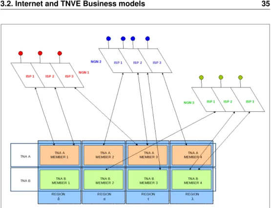
3.2 TNVE business model. . . 35
3.3 TNVE scenario. . . 38
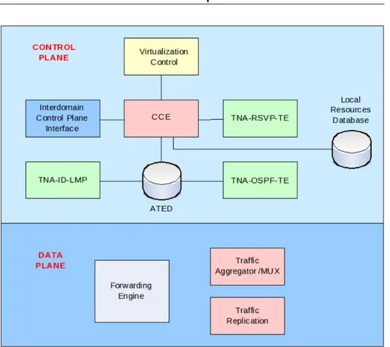
3.4 FIE architecture. . . 40
3.5 A slice space. . . 40
3.6 P2MP circuit provisioning. . . 43
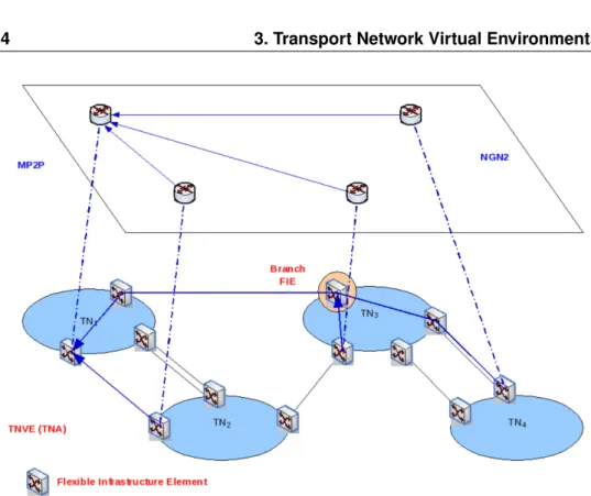
3.7 MP2P circuit provisioning. . . 44
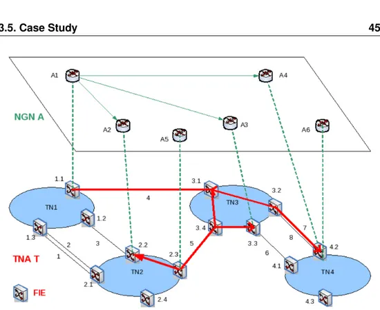
3.8 Case study scenario. . . 45
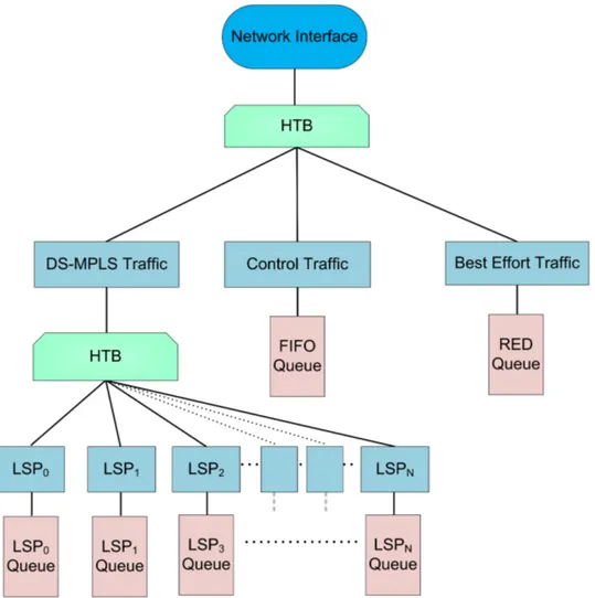
4.1 DS-MPLS Open Framework architecture. . . 54
4.2 Hierarchical scheduler tree. . . 59
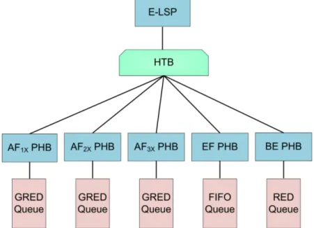
4.3 E-LSP scheduler subtree. . . 60
4.4 L-LSP scheduler subtrees for AF and EF traffics. . . 60
4.5 Collaboration diagram for the centralized LSP setup procedure. . . 63
4.6 Collaboration diagram for the centralized LSP teardown procedure. 64 4.7 LCS internal components and the PCE interaction. . . 65
4.8 LSP setup request sequence diagrams. . . 66
4.9 LSP teardown request sequence diagrams. . . 67
4.10 Packet trace containing PATH and RESV messages. . . 68
4.11 One of the DS-MPLS live distribution boot splash screen. . . 69
5.1 MCP-RWA macro-level flowchart. . . 78
5.2 Cascading of amplifiers. . . 82
5.3 MCP-RWA detailed flowchart. . . 83
5.4 Cost function comparison. . . 85
5.5 Criticality threshold comparison. . . 86
5.6 MCP-RWA mean blocking probability. . . 87
5.7 Confidence intervals for MCP-RWA mean blocking probability. . . . 88
5.8 MCP-RWA processing time. . . 88
5.9 MCP-D2detailed flowchart. . . 90
5.10 MCP-S detailed flowchart. . . 91
5.11 Survivable IA-RWA grid topology blocking probability. . . 93
5.12 Survivable IA-RWA NSFNET topology blocking probability. . . 93
5.13 Survivable IA-RWA Italian topology blocking probability. . . 94
5.14 Survivable IA-RWA American topology blocking probability. . . 94
5.15 Survivable IA-RWA grid topology processing time. . . 95
5.16 Survivable IA-RWA NSFNET topology processing time. . . 95
5.17 Survivable IA-RWA Italian topology processing time. . . 96
List of Tables
2.1 DSCP values for all AF X classes and Y drop precedences. . . 18
3.1 Association between NGNEs and FIEs. . . 45
3.2 TNA Members Characteristics. . . 46
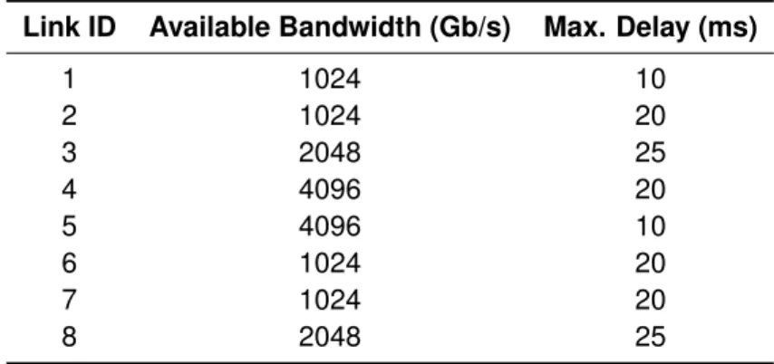
3.3 Interconnection Links TE Properties. . . 46
4.1 Association between DSCP and EXP fields used to setup E-LSPs . 56 4.2 Example of association between FECs and LSPs . . . 57
Papers Published by the Author
†
Journal articles
1. D. Adami, S. Giordano, M. Pagano, L. G. Zuliani, “Multidomain Layer 1 Infrastructure Virtualization as a Future Internet Services-enabling Paradigm,” Journal of Internet Engineering (JIE), Vol. 4, N. 1, pp. 251–259, Dec. 2010. 2. G. S. Pavani, L. G. Zuliani, H. Waldman, M. Magalhães, “Distributed Approaches
for Impairment-aware Routing and Wavelength Assignment algorithms in GMPLS Networks,” Computer Networks (COMNET), Vol. 52, N. 10, pp. 1905–1915, July 2008.
Conference proceedings papers
3. D. Adami, S. Giordano, M. Pagano, L. G. Zuliani, “Online Lightpath Provisioning and Critical Services: A new IA-RWA algorithm to Assure QoT and Survivability,” IEEE International Conference on High Performance Switching and Routing (HPSR 2011), Cartagena, Spain, to appear.
4. D. Adami, S. Giordano, M. Pagano, L. G. Zuliani, “MCP-RWA: A Novel Algorithm for QoT-guaranteed Online Provisioning in Photonic Networks,” International Congress on Ultra Modern Telecommunications and Control Systems (ICUMT 2010), Moscow, Russia, Oct. 2010.
5. D. Adami, S. Giordano, M. Pagano, L. G. Zuliani, “Lightpath Survivability with QoT Guarantees: Developing and Evaluating a New Algorithm,” Int. Symposium on Performance Evaluation of Computer and Telecommunication Systems (SPECTS 2010), Ottawa, Canada, July 2010.
6. D. Adami, S. Giordano, M. Pagano, L. G. Zuliani, “Lightpath Survivability with QoT Guarantees: Key Issues in Wavelength-Routed Photonic Networks,” Int. Conference on Optical Communication Systems (OPTICS 2010), Athens, Greece, July 2010.
7. D. Adami, S. Giordano, M. Pagano, L. G. Zuliani, “On Leveraging Future Internet Services Through Multidomain Layer 1 Virtualization,” IEEE 3rd Workshop on Enabling the Future Service-Oriented Internet (EFSOI’09), Honolulu, USA, Dec. 2009.
8. D. Adami, S. Giordano, M. Pagano, L. G. Zuliani, “A Flexible Software Router based Framework to Enable a DS-MPLS Transport Network,” IEEE 14th Int. Workshop on Computer Aided Modeling and Design of Communication Links and Networks (CAMAD’09), Pisa, Italy, June 2009.
†
The list of authors of all papers exclusively written by TLCNETGRP members are sorted by surname. The author of this thesis acknowledges to be the corresponding author of paper n. 1 and papers n. 3 through 9.
9. D. Adami, S. Giordano, F. Russo, L. G. Zuliani, “A New Framework for the Development and Deployment of Multi-purpose Service Specific Overlay Networks,” Italian Networking Workshop, Cortina d’Ampezzo, Italy, Jan. 2009.
Previously published papers
10. L. G. Zuliani, M. Savasini, G. S. Pavani, R. Pasquini, F. L. Verdi, and M. Magalhães, “An implementation of an OSPF-TE to support GMPLS-controlled All-Optical WDM Networks,” VI International Telecommunications Symposium (ITS2006), Fortaleza, Brazil, Sept. 2006.
11. R. Pasquini, F. L. Verdi, L. G. Zuliani, M. Magalhães, and S. Rossi, “An Optical UNI Architecture for the GIGA Project Testbed Network,” VI International Telecommunications Symposium (ITS2006), Fortaleza, Brazil, Sept. 2006.
Chapter 1
Introduction
Since its creation, the Internet has evolved from an experimental, packet-switched research network to a public, global telecommunication infrastructure that supports applications in all areas of knowledge. As well known, the Internet is a “network of networks”, i.e. a conglomerate of networks mainly owned by large corporations, government and research institutions, universities and ISPs (Internet Service Providers). These administrative domains operate their networks in an independent way, using specific technologies and customized settings (ranging from transport devices to routing and access policies) to best fit their purposes. Nowadays, Internet is composed of thousands of such interconnected networks that are organized as ASes (Autonomous Systems). As described in [1], the IANA (Internet Assigned Numbers Authority ) has begun to assign 32 bits AS numbers, due to the near exhaustion of the old 16 bits format pool. Interoperability among ASes is still based on the original TCP/IP protocol architecture, which was conceived to deliver data in a connectionless, best-effort fashion. Therefore, globally offered Internet services must rely exclusively on the TCP/IP stack of protocols. The main concern by the time of TCP/IP creation was to effectively provide reachability between applications running on different hosts. By the early ’80s, TCP/IP was successful on supporting the applications of that time, namely rsh, telnet, ftp and e-mail.
From the beginning, Internet itself can be seen as a data overlay network on top of a telecommunication infrastructure. Leased lines were deployed to interconnect networks in metro and long-haul (cross-country and overseas) areas, using data-link control protocols like HDLC (High-level Data Link Control). Later on, access was also provided using POTS (Plain Old Telephone Service) and SLIP (Serial Line Internet Protocol), among others. As in any overlay, the upper layer benefits from the under layer resources in transparent or quasi-transparent manner. The Internet overlay was - and still is - no exception to this rule: IP routers have little or no information at all regarding the number and the operational status
of the L1 (Layer 1) circuits that compose interconnection IP links. This was a design feature: TCP/IP would deal with malformed and missing packets, while applications would just have to use the (newly available) sockets API (Application Programming Interface) to reliably transmit information across two end hosts. Internet applications have changed drastically in the last fifteen years. On-demand multimedia delivery, content exchange, videoconferencing, massive multiplayer entertainment, social networks and virtual realities are now part of our daily lives. Two main factors have made possible the emergence of such applications: the tremendous increase of CPU power and network capacity at affordable prices, and the huge effort put by the academic and industry communities to add to the Internet the network functionalities requested by today’s applications. The latter was realized using the so called incremental approach, that can be summarized with the development of new IP-based protocols and extensions of the existing ones, and also with the creation of new overlay solutions on top of the Internet. As the IP network layer has no visibility of its underlayers, i.e. the telecommunication transport infrastructure, solutions have to rely on simple monitoring tools (like ping or traceroute) and/or complex probabilistic algorithms in order to minimize service disruption and maximize the QoE (Quality of Experience) of users. Therefore, the Internet as it is today can globally offer, under the best conditions, just better-than-best-effort services [2,3].
Considering the same period of the last fifteen years, a wide range of network challenges were overcome with innovative solutions, specially in the field of seamless mobile and QoS-guaranteed (Quality of Service) communications. These advances, however, have seen little to none deployment on the Internet at large. Unfortunately, the Internet has suffer from a natural evolutionary process that any successful technology is subjected to. This stagnation process is called ossification, and poses a severe obstacle to the continuing evolution (and even the survival) of the Internet [4]. The ICANN (Internet Corporation for Assigned Names and Numbers) made an official communication on February 3rd, 2011 stating that the IPv4 address pool is already depleted [5]. By the time of this writing, it is predicted that all IPv4 address still not allocated by ICANN-affiliated regional organizations will be over in the next months. Even facing this critical situation, the global deployment of IPv6 [6] (the next version of IP, that uses 128 bits of addressing space instead 32 bits of IPv4) is still not a reality. So far, incremental approach solutions were convenient. In fact, the potential service disruption caused by the adoption of new, non IP-compatible protocols could lead to catastrophic financial consequences, to say the least.
A whole myriad of innovative, highly profitable services is being predicted for the future Internet, driven by a number of factors such as quality and cheap ubiquitous access (anywhere, at any time, and from any device), the proliferation of user-generated content, and the new advances in human-computer interaction. These new services will require new (or higher levels of) capabilities concerning
3
seamless access, mobility and multi-homing, content- and context-awareness, privacy, anonymity, security, identity and trust management, accounting, and QoS [7]. These future Internet services simply can not be leveraged by just adding new functionalities to end systems, leaving the network core untouched. Moreover, many (if not all) network functionalities essential to future Internet services can not be achieved by IP-based protocols, at least without facing scalability issues [8]. Between all of these functional requirements, one of the most delicate is Internet QoS. IP QoS is complex, expensive and not straight-forward to implement even in small scale scenarios. It is much simpler and cheaper to workaround QoS-related problems with overprovisioning. As stated in [3], “... trying to introduce QoS in IP routed and connectionless networks is indeed a Utopian idea. This is like trying to introduce fine cuisine, gourmet dishes, and a la carte menus in fast food restaurants. In other words, IP QoS is not the right approach for Internet QoS.”. To circumvent current Internet limitations and to provide the proper ground to leverage advanced future Internet services, new network architectures and protocols suites are being envisioned. Proposals for networks that incorporate such pioneer elements are commonly called NGNs (Next Generation Networks). It is worth to note that the term NGN in this thesis do not intend to make reference to any specific network solution, unless when explicitly cited. So far, the available NGN proposals are very heterogeneous (ranging from sub-IP protocols to complete clean slate designs [9]), and usually are data transmission technology independent. It is still unclear how NGNs will be realized, but a number of paradigm-shifts already have been defined. While current Internet is based on best-effort service provisioning, NGNs will feature assured provisioning. Instead of providing communication capabilities between end-hosts, connectivity services will be provided by NGNs upon application request. On-request service invocation will be replaced by on-demand service invocation. Finally, the vertically-oriented, application-specific approach will give place to a horizontally-integrated, multi-service network [10].
There appear to be a consensus that, while focusing on user services, NGNs should keep the interaction with the underlay infrastructure as transparent as possible. Indeed, the wide variety of data hauling technologies and the intricacy of their organizational structure would pose a huge obstacle to the development of NGNs, if managed with full visibility. Some questions arise from this observation: will it be possible to meet future applications requirements -specially QoS related ones - without visibility of the underlay infrastructure? If so, how could it be achieved? The answer could rely on network virtualization. By this principle, multiple, specialized NGNs could share a single physical substrate, without compromising flexibility, manageability, fault tolerance, security and privacy [11]. In the future Internet scenario, the physical substrate is the telecommunication infrastructure that provides backbone and long haul L1 optical circuits. It is expected that this infrastructure will be primary composed by WRPNs
(Wavelength Routed Photonic Networks) controlled by the GMPLS (Generalized MultiProtocol Label Switching) [12] suite of protocols [13]. Therefore, the control entities of the virtualized physical substrate must orchestrate multiple GMPLS L1 networks in order to offer infrastructure services at a global scale. In other words, the virtualization control must cope with interdomain provisioning among independent carriers. As stated in [11], “... virtual networks embedding across multiple infrastructure providers is still a virtually untouched problem.”.
Since the dawn of modern telecommunications, there are only two cases of success concerning interdomain CP (Control Plane) standardization: SS7 (Signaling System No. 7 ) [14] and BGP (Border Gateway Protocol) [15]. No matter GMPLS is being successfully deployed today to offer automatic provisioning of circuits in intradomain scenarios, it completely fails to provide interdomain provisioning so far [16]. One key aspect that has turned SS7 and BGP into successful technologies is the ability of these solutions to satisfy commercial agreements, without compromising internal network manageability or disclosing critical information regarding the network operational status. Indeed, the BGP policy-driven routing mechanism restricts the full exploitation of the underlying topology, as physical connectivity between ASes does not imply reachability [17]. The GMPLS standardization process main concern regards the technical aspects of provisioning control. Commercial relations between carriers and the economic aspects of those relations were completely ignored by GMPLS. GMPLS-controlled WRPNs are already being deployed commercially. However, the available circuit provisioning techniques still can not fully exploit the potential of WRPNs. L1 optical circuits, better known as LPs (Lightpaths), are calculated by RWA (Routing and Wavelength Assignment) algorithms. In a GMPLS-controlled WRPN, one or more RWA algorithms are implemented in PCEs (Path Computation Elements) [18]. RWA algorithms are very complex to design, and the quality of results are proportional to the network DP (Data Plane) status information (made available by the CP) and by the time available to calculation. Over the last fifteen years, the RWA problem has been extensively researched. Despite all advances in the field, the state of the art RWA algorithms still do not deliver the desired performance levels for WRPNs on support of future Internet services. In this case, LPs tend to have shorter duration, may be sensible to setup delay and, most important, may required assured QoS even in case of network failures. Current RWA algorithms can not offer a reasonable trade-off balance between speed and blocking probability, considering the available data from GMPLS CPs and all-optical monitoring devices.
Clearly, the future of the Internet relies in the successful development and deployment of NGNs. And NGNs, to succeed in their mission, must be supported by intelligent, global network infrastructures that will bring to the game new functional capabilities. In order to make these intelligent infrastructures a reality,
1.1. Motivations 5
two challenges must first be overcome: how to organize multiple L1 carriers to render them capable to provide, at an intradomain level, the same service levels that can be achieved internally to each transport network; and also, how RWA algorithms can be enhanced to fully exploit all the potential of WRPNs. This thesis describes three works aimed to address these questions.
The first proposal presents a preliminary architecture to manage and control the services and resources of a set of L1 transport networks, allowing many NGNs to contemporaneously benefit from the multidomain physical infrastructure, seamless and effortlessly. By using network virtualization techniques, NGNs are able to interact with the physical underlayer as it was a dedicated, single domain infrastructure. All L1 infrastructure group members have a strong business relationship between them, and exchange a limited amount of information (including monetary cost of resource allocation) that is enough to provide advanced services such as QoS guaranteed point-to-multipoint circuits.
The second contribution regards the development of a framework that enables the creation of pseudo virtual circuits with assured QoS, using exclusively open source software and commodity PC hardware. The framework is not a simple collection of network tools that are bundled together, but a highly integrated set of systems that performs well-defined tasks. An embedded CP permits the automatic provisioning of circuits, yet offering a great amount of flexibility. The framework is available as live distributions, allowing the configuration of a physical router or even an entire virtual network in few minutes. It is designed to serve as a QoS platform to allow rapid NGN prototyping, and also as an advanced learning tool for graduate networking courses.
The third proposal consists in the development of advanced, survivable RWA algorithms for WRPNs. The main goal of the proposed algorithms is to provide absolute levels of QoS, and guarantee that no service disruption will occur even in the event of single network failures. The proposed RWA algorithms use a highly parallelizable path computation engine and simple heuristics in order to be fast and maximize the resource utilization, therefore minimizing the blocking probability of future LP setup requests.
1.1
Motivations
• The current inability of the GMPLS architecture to fulfill the requirements of interdomain LP provisioning, due to, among other reasons, the intrinsic lack of economic aspects support and commercial agreements considerations. • The nonexistence of virtualization architectures that allow a substrate to be
composed of multiple domains.
software and commodity PCs to provide pseudo virtual circuits and QoS. • The incapacity of state of the art RWA algorithms to satisfy the demanding
requirements of future Internet services, when concerning LP provisioning.
1.2
Contributions
• A preliminary architecture to enable advanced, future Internet services through L1 multidomain virtualization techniques.
• The development of an open DS-MPLS framework and a flexible software router to aid NGN prototyping, that could also be used as a tool for advaced networking learning.
• The creation of three new RWA algorithms, that introduce novel techniques to perform better than state of the art RWA algorithms, considering processing time and blocking probability as performance metrics.
1.3
Text Organization
Chapter2 discusses the technology background involving the works introduced in this thesis. Chapter 3 introduces the TNVE architecture; related works in the area along with current and future business models are also presented. Chapter 4 details the open DS-MPLS framework and the developed DS-MPLS router. Chapter5introduces the novel RWA algorithms specifically envisioned to WRPNs in support of future Internet services. The state of the art RWA algorithms are initially depicted, followed by detailed descriptions of the proposed algorithms and the evaluation process. Finally, in Chapter6conclusions are drawn.
Chapter 2
Background
This chapter presents an overview of the main concepts and technologies involved in this work, in order to provide the appropriate basis to a deep comprehension of the proposals presented in this thesis. The first section reviews the optical transmission systems and introduces the cutting-edge, all-optical networks. The second section discusses two of the most important attempts to introduce QoS in the Internet, namely IntServ and Diffserv. Next, the third section introduces the MPLS switching, while section four discusses integration models for DiffServ and MPLS. The fifth section overviews the GMPLS architecture and its main protocols, and finally the sixth section briefly introduces some network virtualization concepts.
2.1
Photonic Networks
In the early ’70s, the first optical transmission systems started to be deployed commercially. At that time, optical networks were formed by point-to-point links which transported only one signal (for example SONET/SDH) per optical fiber, modulated in only one wavelength (usually referred by the Greek letterλ). To cope with the rapidly increasing demand for bandwidth, a whole set of strategies to boost the bulk transmission capacity of optical telecommunication systems were proposed. The solutions ranged from simple deployment of new fibers to more intricate ones, such as increasing the bit rate of TDM (Time Division Multiplexing) channels. These were not practical solutions, considering the costs associated with fiber deployment and the technical difficulties regarding increasing the transmission capacity of optical carriers. This scenario has motivated the development of the WDM (Wavelength Division Multiplexing) technology. In a WDM optical network multiple channels modulated in different wavelengths are multiplexed and then contemporaneously transmitted in a single fiber. The WDM principle is analogue to FDM (Frequency Division Multiplexing), that allows the
contemporary transmission of a number of signals modulated in different carriers without overlapping. Therefore, the original transmission capacity of every single fiber is multiplied by the number of channels supported by the WDM system [19]. The main components of WDM systems are discussed in the following subsections.
2.1.1
Optical Fibers
Fiber optics are used to guide wavelengths between optical network devices with a minimum level of attenuation (signal loss), which varies with fiber quality and length. Fibers are formed by (at least) two layers of different type of silica glass, named core and cladding. Doping techniques are used during the manufacturing phase of modern fibers, in order to considerably alter the index of refraction of silica glass. Due to the lower index of refraction of the cladding, the optical signal is transmitted in the interior of the core at 2/3 of its velocity in vacuum, by the
principle of total internal reflection.
Fibers can be divided in two categories: multimode and monomode. WDM systems use monomode fibers, due to the huge bulk transport capacity and intrinsic low loss of these fibers. Monomode fibers are careful designed and crafted to the specific use of certain regions of the optical spectrum that present the lowest levels of attenuation. These regions are called windows. Nowadays, the windows more commonly used by WDM systems are the S-band (1460 to 1530 nm) and the C-band (1530 to 1565 nm) [20]. The L-band (1565 to 1625 nm) is of particular interest to cutting-edge DWDM (Dense Wavelength Division Multiplexing) systems.
2.1.2
Optical Transmitters and Receivers
Light emitters and detectors are active devices that are found in opposing extremities of optical transmissions systems. Light emitters are transmitters that convert electric signals in light pulses. On the other hand, light detectors do exactly the opposite, i.e., transform received light pulses in electric signals. Two classes of light emitting devices are used in optical transmission systems: LEDs (Light Emitting Diode) and semiconductor lasers. WDM systems are designed with semiconductor lasers, due to the precise wavelength tuning, narrow band spectrum, high optical power and chirp control (signal frequency variation over time). Depending of the type of the semiconductor laser used, wavelengths of optical signals must first be adjusted before being injected in fiber links. This task is performed by an optical device called transponder.
At the reception end, it is necessary to recover the information carried in the electrical domain before being hauled by WDM transmission lines.
2.1. Photonic Networks 9
Photodetectors are employed for this task. Two types of photodetectors are vastly used: PIN (Positive-Intrinsic-Negative) photodiodes and APD (Avalanche PhotoDiode). While PINs are cheap and robust, APDs have greater precision and reception sensibility.
2.1.3
Physical Impairments and Regenerators
Optical signals traversing the network through optical fibers and devices are subject to QoT (Quality of Transmission) degradation by a number of physical layer (or transmission) impairments. Among those, the most relevant factors are chromatic dispersion, PMD (Polarization Mode Dispersion), ASE (Amplified Spontaneous Emission) and the so called nonlinear effects.
Chromatic dispersion [21] is not an issue in modern WDM systems anymore. It can be compensated on a per-link basis, during the WDM network design phase. PMD compensation [22] in turn is very difficult to perform, and is the principal challenge in the deployment of cutting edge 40 Gb/s and beyond systems. In today’s production networks, PMD effects over QoT are usually avoided by setting up an upper bound for the length of LPs, although it is far from optimal. However, the maximum allowed LP length constraint tends to be relaxed, due to quality enhancements in optical fibers (smaller PMD parameters) and late advances in all-optical PMD compensation [23].
ASE degrades the OSNR (Optical Signal to Noise Ratio), and is one of the dominant impairments at any bit rate. ASE noise accumulates as the optical signal traverses a path, and saturation effects may disturb the effectiveness of signal amplification, influencing the BER at the receiver. De-multiplexing filters can strengthen the ASE noise leading to linear crosstalking as well. ASE noise can be acquired either by approximate calculation (using information directly from network elements such as optical input power and losses) or by measuring. In the later case, the WDM network must be equipped with OPM (Optical Performance Monitoring) devices [24].
Nonlinear impairments [25] strictly depend on optical power and are the most difficult ones to be treated. Examples are stimulated Raman and Brillouin scattering, four-wave mixing, self phase and cross phase modulation. They can substantially affect the performance of very dense DWDM systems due to nonlinear crosstalking.
To compensate the degradation of light pulses, regenerators are traditionally placed along fiber links. Regenerators are devices formed by optical and electronic components, capable of reamplifying, reshaping and retiming optical signals. This operations is called 3R (Reamplification, Reshaping and Retiming) regeneration. Each single wavelength is regenerated individually, involving OEO conversion. Usually, optical signals can be transmitted up to 120 km without amplification. For distances greater than 600 km amplified signals become noisy
and distorted, thus they must be reshaped and retimed [26].
2.1.4
Optical Amplifiers
The technology breakthrough that made WDM transmission lines a reality was the optical amplification advent. Optical amplifiers are devices that, diversely from regenerators, amplify all wavelengths at once, without conversion to the electrical domain. By far, the most used type of optical amplifiers is EDFA (Erbium Doped Fiber Amplifier ). Using a pump laser, a light pulse is injected in the erbium doped fiber.This light pulse stimulates the erbium atoms to release photons in wavelengths around 1550 nm.
The main performance parameters of optical amplifiers are the optical gain, the noise level and the saturation power.
2.1.5
WRPNs
Traditionally, optical networks are formed by WDM transmission lines and OLTs (Optical Line Terminals), that perform (de)multiplexing and OEO conversion at each hop in order to add, drop or forward data. These types of networks are known as opaque networks. All the complexities of the optical layer are dealt during the design and deployment stages, and they are not taken into account during provisioning. However, such networks have issues with cost and power efficiency, and cannot leverage modern applications due to slow provisioning time (days, even weeks). Moreover, OEO conversion is the bottleneck for routing at the optical layer. Indeed, the electronic switching matrix of opaque network elements do not have enough processing power to electronically route data hauled by modern WDM systems, that can carry dozens of channels in a single fiber at speeds up to 40 Gb/s per channel.
WRPNs are slowly been adopted to circumvent the limitations of opaque networks [27]. WRPNs are composed of PXCs (Photonic Cross-Connects, also known as All-Optical Cross-Connects) that are able to perform OCS (Optical Circuit Switching) entirely in the optical domain, without the need of OEO conversions. A PXC can be basically divided in two parts: an all-optical switching matrix and a port complex, as illustrated in Figure2.1. The switching matrix is responsible to route incoming wavelengths from the PXC input interfaces to the output interfaces. These interfaces form the port complex, whith connects the PXC to other network elements using optical fibers. Border PXCs are equipped with OADM (Optical Add/Drop Multiplexers) to allow vertical data exchange between the optical cloud and the clients of the optical layer. Data about to be carried by a WRPN are converted to the optical domain at the ingress PXC, and remain in the form of an optical signal while traversing the network.
2.1. Photonic Networks 11 ... 2 λ λK 1 λ λ1 K λ ... 2 λ λK 1 λ λ1 K λ ... 2 λ λK 1 λ λ1 K λ ... 2 λ λK 1 λ 1 λ K λ ... 2 λ λK 1 λ 1 λ K λ ... 2 λ λK 1 λ 1 λ K λ
Input
Fibers
Output
Fibers
Mux
Upper Layer Network Element
λ
Demux
λ
1 .. ... . 2.
..
M ... ... ... 2 1...
M ...All−Optical Switching Matrix
Add / Drop
Figure 2.1: A PXC formed byM fibers, each one carringK wavelengths.
The main advantages and drawbacks of WRPNs come from the same reason: the absence of OEO conversion. Data are carried at high throughput transparently by LPs, thus they can have any format or rate. On the other hand, optical signals are not regenerated in WRPNs. Therefore, optical transmission impairments [28] are accumulated while wavelengths traverse the network. These physical layer impairments degrade the optical signal quality and indirectly affect the BER of traffic being carried. While opaque networks usually have point-to-point or ring topologies, WRPNs tend to be meshed, with longer links and larger number of nodes. In this scenario, a given LP may not be eligible to haul traffic due to poor QoT, even if there are abundant available resources.
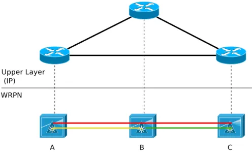
The set of LPs established in a WRPN reflects the topology of the client networks of the WRPN. Figure2.2shows an IP network on top of a WRPN. In this scenario, three LP were previously setup (A-B, A-C and B-C). The LP topology formed by these circuits is in fact the upper layer IP topology (where all routers are adjacent), that is different from the WRPN one (a line topology). Thus, the LP topology is also known as the virtual topology.
Figure 2.2: An IP network on top of a WRPN.
2.1.6
RWA
In order to establish a LP in a WRPN, it is necessary to select not only a path between the ingress and egress PXCs, but also a wavelength to modulate the optical signal on that path. This problem is known as RWA . RWA algorithms can be divided in two main categories:
Static RWA
RWA algorithms of this class are useful when the traffic matrix is known before the WRPN becomes operational. Hence, the static RWA problem is solved by offline algorithms. Usually, their goal is to minimize the number of wavelengths necessary in order to establish a certain set of LPs, given a WRPN with a known topology. Another alternative is to maximize the number of LPs that can be setup, considering a fixed number of wavelengths.
Dynamic RWA
In this case, the traffic matrix is not known a priori. LP setup and/or teardown requests arrive in an (usually) unpredictable fashion. Thus, dynamic RWA problem is solved by online algorithms. The objective of these algorithms is to satisfy the incoming requests, and if possible to minimize the blocking probability of future requests.
The RWA problem is subject to a number of constraints that do not affect the routing process in packet networks. As a result, it is possible that a LP setup
2.1. Photonic Networks 13
request is blocked even if there are unused network resources. These additional restrictions can be sorted in three groups:
Wavelength-continuity constraint
Data being carried by a LP in a WRPN remain in the optical domain all the time. As the all-optical wavelength conversion (without electronic processing) is still an immature technology, the same wavelength must be assigned to all links that together form the LP path.
Diversity constraint
This restriction is taken into account only by survivable RWA, i.e., when the LP to be setup is intended to carry protected data. Two or more LPs are called “diverse” if they are not subjected to be disrupted simultaneously by a network failure. In most of the cases, LP diversity means link-disjoint paths. Physical layer impairments
As optical signals are not regenerated anymore, the physical impairments discussed in subsection3.4can not be ignored when establishing LPs in WRPNs. Algorithms that consider physical layer impairments in order to provide LPs with QoT are known as IA-RWA (Impairment Aware Routing and Wavelength Assignment).
To achieve optimal solution, the RWA problem is formulated using MILP (Mixed-Integer Linear Programming), which requires a high computational power even for not so complex topologies. MILP techniques are used to solve offline the static RWA problem, considering that time is not a hard constraint. Online RWA algorithms, on the other hand, must have a total run time as short as possible, as the time necessary to satisfy a LP setup request in a WRPN can be as low as some tens of seconds. To accomplish this task, traditionally the RWA is divided in two sub-problems. The routing and the wavelength assignments are solved independently, using heuristics that provide sub-optimal results in feasible times. The most important wavelength assignment heuristics today are FF (First-Fit), LF (Last-Fit), BF (Best-Fit), MU (Most-Used ) and RP (Random-Pick ). The routing subproblem can be solved using SPF (Shortest Path First) algorithms, such as the Dijkstra algorithm. Some approaches calculate routes offline for every possible source-destination pair, leaving only the wavelength assignment to be carried out after a request for LP setup has arrived. When only one path for every source-destination pair is calculated, the heuristic is called FR (Fixed Routing). When more than one path (three is a common value) is precomputed for all source-destination pairs, this approach is known as FAR (Fixed-Alternated Routing) [29,30].
2.2
Internet and QoS
The Internet was conceived to deliver packets according to the BE (Best Effort) forwarding paradigm. BE Internet service delivery can be defined as FIFO (First-In First-Out) queuing and LIFD (Last-In First-Drop) tail-first dropping. The QoS (in terms of packet delivery delays and drops due to buffer overflow) of BE service depends not only on the network actions (which the network can control), but also on the offered load (which the network cannot control). Thus, in BE service, the network tries to forward all packets as soon as possible, but cannot make any quantitative assurances about the QoS delivered [31].
The first attempt to offer some sort of relative QoS provisioning is described in the original “DARPA Internet Program Protocol Specification” [32], later updated in [33]. These documents respectively introduce and redefine the TOS (Type Of Service) octet of the IP header, which guide the selection of the actual service parameters when transmitting a datagram through a particular network. The TOS octet is shown in Figure2.3.
1 2 3 4 5 6 7 8
TOS MBZ
0
PRECEDENCE
Figure 2.3: The TOS octet, part of the IP header. The TOS octet is composed by three fields, namely
Precedence
Denotes the “importance” of the datagram, and specifies seven priority levels: • Routine • Priority • Immediate • Flash • Flash Override • CRITIC/ECP • Internetwork Control • Network Control
2.2. Internet and QoS 15
TOS
Denotes how routers should treat the IP packet, making tradeoffs between throughput, delay, reliability, and cost. Five values (out of the sixteen allowed by 4 bits) have been defined:
• Normal Service
• Minimize Monetary cost • Maximize Reliability • Maximize Throughput • Minimize Delay MBZ (Must Be Zero)
Unused field, must always be set to zero.
No matter that [33] defines in detail the scope and properties of the TOS octet, it does not specify how routers should enforce traffic prioritization. Indeed, the TOS facility never has been really adopted in large scale. Even when the TOS field of IP packets was filled by hosts (only Unix systems by that time), the vast majority of routers completely ignore it during the routing process.
As new QoS-sensitive Internet applications (like multimedia content delivery) started to appear, the need for a QoS-aware Internet arose. During the last two decades the industry and academic communities have proposed a number of solutions, with different levels of success, to render the Internet a better platform to leverage QoS-sensitive applications. Two of these proposals are briefly described in the next subsections.
2.2.1
IntServ
The Integrated Services model, or simply IntServ [34], aimed to provide end-to-end QoS between host applications using reservation techniques. It extends the original Internet architecture introducing new components and functionalities, without compromising the standard BE forwarding of IP networks. IntServ defines methods for identifying traffic flows, and controls the end-to-end packet delay on a per-flow basis. This is achieved by a mechanism called controlled link-sharing. The IntServ model introduces the following services: Guaranteed Service
Used by applications that are sensitive to delay and jitter, thus requiring real-time service delivery. Each router in the path must reserve network resources in order to guarantee absolute QoS levels for the requested service.
Controlled-Load Service
Used by applications that are not strictly delay sensitive, but can not perform well in overload conditions. Controlled-load offer low queueing delay and low packets loss services to application, without implementing complex per-flow control mechanisms.
The IntServ architecture introduces the building blocks later used by many QoS frameworks for IP networks. The four main components of the IntServ architecture are:
Scheduler
manages the packet forwarding of different flows using a set of queues and timers. Schedulers perform per-flow statistics of forwarded packets (either measuring or estimating the outbound traffic), also usefull for the admission control.
Admission Control
determines if the QoS level specified in a new service request can be granted without compromising the other preestablished flows. Also, it is in charge of administration tasks such as the service request authentication and billing.
Classifier
using IP header information, its task is to arrange packet flows in groups. Different flows belonging to a same group, called class, receive the same forwarding treatment. A class can be locally abstracted. For example, backbone routers can aggregate many flows in few classes, while access routers can map a single flow per class.
Resource Reservation Protocol
necessary to manage flow requests and perform maintenance of flow status along the path. For this purpose, IntServ uses the RSVP (Resource ReserVation Protocol) [35].
2.2.2
DiffServ
By the time of IntServ standardization, concerns about scalability in large scenarios have appeared. Indeed, to keep record and provide maintenance of flow-states is a heavy burden to routers, which must have at disposal a great amount of storage capacity and processing power. The Differentiated Services architecture (shortly DiffServ [36,37]) was designed with scalability as the main concern, and is intended to be simpler than Intserv. The per-flow service was substituted with per aggregate service, and the complex processing moved from the core to the edge of networks [38].
2.2. Internet and QoS 17
Diversely from IntServ that uses RSVP to allocate resources in real-time, the Diffserv model provides services using QoS parameters described in preestablished SLAs (Service Level Agreements) between customers and ISPs. Accordingly to the traffic aggregate that a packet belongs to, it receives a mark that is storage in the TOS octet, now renamed as the DS field [39]. The mark is placed in the first six bits of the DS Field, a subfield called DSCP (DiffServ Code Point). Each DSCP value indicates a different packet forwarding treatment at each router, which are called PHB (Per-Hop Behaviour ). The DS Field structure is shown in Figure2.4. The two last bits of the DS field were defined as “Currently Unused” by the DiffServ architecture and should be ignored by DS-routers, but at the present time these two last bits are used to incorporate ECN (Explicit Congestion Notification) to IP and TCP [40].
0 1 2 3 4 5 6 7 8
DSCP CU
Figure 2.4: The DS Field structure (redefinition of the TOS octet of the IP header). Initially, three types of PHBs have been defined. Later on, configuration guidelines have been made available [41]:
Default (DE)
The standard BE forwarding paradigm. Packets with the a DSCP value equal to 000000 or packets with an unrecognized value are forwarded using the DE PHB.
Expedited Forward (EF) [42,43]
This PHB provide a low-loss, low-delay, low jitter service. Its DSCP value is 101110, and can be implemented with a short buffer, priority queue. More complex schedulers such as DRR (Deficit Round Robin) and WFQ (Weighted Fair Queuing) can also be used to implement EF services. Being the PHB with the highest QoS profile specified by the DiffServ model, it is also the most expensive. Therefore, EF services are often called premium services. Non-conformed EF traffic is silently dropped.
Assured Forward (AF) [44,37]
This PHB does not consider upper bounds for QoS parameters like delay or jitter. Instead, it forward packets with a high probability of delivery, considering that the traffic conforms to the contracted rate. Traffic that do meet SLAs are allowed, but are subjected to be discarded. AF services
can be described as “Better-than-Best-Effort”. Four class of services have been defined in the AF PHB, and each one has three possible discard levels known as drop-precedence. The higher the drop-precedence, the higher is the probability that the packet is discarded. The AF PHB is usually implemented with RED (Random Early Detection [45] or one of its variants, like RIO (RED with In/Out) [46]. Table 2.1depicts the defined AF classes and associated DSCP values.
Table 2.1: DSCP values for all AF X classes and Y drop precedences. Drop Prec. AF 1Y AF 2Y AF 3Y AF 4Y
AF X1 (Low) 001010 010010 011010 100010
AF X2 (Med.) 001100 010100 011100 100100
AF X3 (High) 001110 010110 011110 100110
A DS-enable router performs two additional functions: packet classifying and conditioning. The former is responsible to correlate a packet with an PHB, using the IP header data (the DS Field can be overridden, if previously set by another domain). The later uses the result of packet classification as input to enforce SLA profiles on traffic aggregates. The DiffServ Traffic Conditioner is composed by a meter, a marker, a shaper and a dropper. The functional flowchart of the DiffServ Model is illustrated in Figure2.5.
Classifier
Packet Marker Shaper /
Dropper Meter
Traffic Conditioner
Packets Packets
2.3. MPLS Switching 19
2.3
MPLS Switching
Since the late ’80s, network vendors have began to bundle new functionalities in IP routers on an attempt to cope with the ever growing Internet traffic. Due this increasing complexity, the gap between layer 3 routers and layer 2 switches were also increasing, when comparing their forwarding capacities. By the early ’90s, ATM (Asynchronous Transfer Mode) networks were used to haul IP packets at higher speeds and longer distances, despite the high overhead of IP-over-ATM encapsulation models like LANE (LAN Emulation) and MPOA (MultiProtocol Over ATM). This scenario paved the way for the development of technologies that brought to the network layer the connection oriented, packet forwarding paradigm, by means of label switching. In 1997, the IETF (Internet Engineering Task Force) has created a working group to standardize these technologies. The new standard was baptized with the vendor-neutral name of MPLS (MultiProtocol Label Switching) [47].
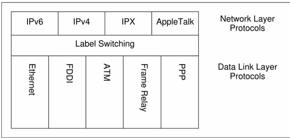
In traditional BE delivery, IP packets are forwarded by routers using exclusively the information in the IP header. Almost always, only the destination field is used. In a MPLS network, the IP header data is used only at ingress routers to map packets in FECs (Forwarding Equivalence Classes). A FEC describes a set of packets that have similar or even identical characteristics. Packets belonging to the same FEC are routed using the same criteria. Each packet entering the MPLS cloud is associated with a FEC and receives a label, that will be used by the routing process to forward the packet throughout the network. Figure 2.6 depicts the possible combinations of link layer and network protocols that can be integrated by the MPLS standard.
IPv6 IPv4 IPX AppleTalk
FDDI Frame Relay
Ethernet ATM PPP
Label Switching
Network Layer Protocols
Protocols Data Link Layer
Figure 2.6: Link layer and network protocols that can be integrated by the MPLS standard.
in their cells or frames to carry the label information. When this is not possible (for example in Ethernet networks), a shim header is introduced between the headers of layers 2 and 3. The shim header has 32 bits, and is composed by four fields: Label
Label value (20 bits). EXP
Experimental Use (3 bits), now renamed to TC [48].1 S
Bottom of Stack (1 bit). TTL
Time to Live (8 bits).
Figure 2.7 shows the shim header between the link layer and network headers. Layer 2 header Shim header 0 2 3 2 4 2 2 3 EXP (TC) Layer 3 header Layer 3 payload 0 Label S TTL
Figure 2.7: Shim header between the link layer and network headers. Inside the MPLS cloud, each LSR (Label Switching Router ) has a database called LFIB (Label Forwarding Information Base), which contains all the information necessary to forward packets. When a packet arrives at a core LSR, its label is used to perform a lookup at the LFIB. Each incoming label is associated to an outgoing label and interface, that are used to quickly forward the packet. When a packet leaves the MPLS core, the shim header (if present) is removed. The path used by the packets of a given FEC to cross the MPLS network is called LSP (Label Switched Path).
1
As the TC designation is still new and not widely used, and also by the fact that the term TC index is used in Linux traffic control (which in the context of this thesis is closely related to the EXP field), it has been decided to still use the previous ‘EXP’ terminology to refer to the second, 3 bits field of the shim header.
2.4. DS and MPLS integration 21
2.4
DS and MPLS integration
By using DS alone, ISPs are able to prioritize premium traffic applying distinct PHB to different traffic aggregates. However, the DS model essentially offers relative QoS, and the only way to meet strict SLA requirements is to provide enough resources to avoid chronic congestions. MPLS itself allows ISPs to perform TE (Traffic Engineering), balancing the network load and assuring protection and absolute QoS for LSPs. Nevertheless, the concept of CoS (Class of Service) differentiation is not defined by the MPLS. If multiple flows are associated with a given LSP (by using one or more FECs), the non-conforming aggregate traffic will be shaped (and eventually dropped) without distinction between the flows carried by the LSP. Therefore, DS and MPLS are complementary technologies, that together allows per-CoS resource allocation and protection, without the need of over provisioning [49].
Two standards were proposed by the IETF to unify DS and MPLS. The first proposal is best know as “DiffServ over MPLS” [50], and specifies two different types of LSPs specially designed to carry DS traffic:
E-LSP (EXP-Inferred-PHB Scheduling Class LSP)
The EXP field of the MPLS shim header is used by LSRs to determine the PHB to be applied to the IP packet. Thus, an E-LSP can support up to 8 distinct PHBs, drop precedences included. The mapping between PHB and EXP values can be statically defined or negotiated online, during the LSP signaling process.
L-LSP (Label-Only-Inferred-PHB Scheduling Class LSP)
Only one PHB is applied to all packets belonging to the FEC. The PHB is associated using exclusively the label during the LSP setup phase. In case the PHB is AF, the drop precedence information is stored in the EXP field of the shim header.
The second proposed unification model is called “DiffServ-aware MPLS TE”, or simply “DS-TE” [51,52]. Some definitions used by DS-TE are:
Traffic Trunk
an aggregation of traffic flows of the same class which are placed inside a LSP.
CT (Class-Type)
the set of Traffic Trunks crossing a link, that is governed by a specific set of bandwidth constraints. CT is used for the purposes of link bandwidth allocation, constraint based routing and admission control. A given Traffic Trunk belongs to the same CT on all links.
TE-Class
a tuple formed by a CT and a preemption priority allowed for that CT. DS-TE defines eight TE-Classes, (from TE0 to TE7), eight CTs (from CT0 to CT7) and eight priority levels (from 0 to 7). Each ISP has the flexibility to specify how each TE-Class is formed, based on the 64 possible combinations between the available CTs and priority levels. For example, if an ISP wants to be able to preempt BE traffic in favor of voice traffic, but also preempt voice traffic from customer A in favor of voice traffic from customer Z, the follow TE-Classes can be defined:
TE0 [CT0, priority 0]: voice traffic (EF PHB mapped to CT0), customer Z TE1 [CT0, priority 1]: voice traffic (EF PHB mapped to CT0), customer A TE2 [CT1, priority 7]: BE traffic (BE default PHB mapped to CT1)
Two different bandwidth constraint models are proposed to be used with DS-TE: MAM (Maximum Allocation Model) and RDM (Russian Dolls Model) [53]. MAM assigns portions of the link bandwidth to each defined CT, which are completely isolated from each other. This means that the preemption priorities are considered only between LSPs carring traffic of the same CT. RDM, in the other hand, allows bandwidth sharing between different CTs. With this model, CT0 traffic (usually mapped as EF) can use the bandwidth allocated to all other CTs (CT7 is mapped as the BE default PHB). While RDM provides efficient bandwith sharing between all traffic trunks traversing the network, preemption is needed to guarantee bandwidth to all CTs.
2.5
GMPLS Architecture
Lower layer networks usually rely on heterogeneous, non packet-based switching mechanisms, i.e., cannot forwarding data using information carried in packet or cell headers. The ability to perform fast, automatic circuit provisioning in these networks, that currently are the foundation of the Internet infrastructure, are key to reduce CAPEX (Capital Expenditure) and OPEX (Operational Expenditure) and also to generate revenue. GMPLS extends the original MPLS architecture to support LSP provisioning in networks where switching decisions are based on time slots, wavelengths, or physical ports. Moreover, GMPLS introduces new features, like complete separation of CP and DP, bidirectional LSPs, link bundling, unnumbered links, and forwarding adjacencies [12]. GMPLS can also be seen as an IP-based instantiation of the protocol independent ASON (Automatic Switched Optical Network ) [54] architecture, proposed by ITU-T (International Telecommunication Union - Telecommunication Standardization Sector ).
2.5. GMPLS Architecture 23
The GMPLS suite of protocols consists of both new and extended MPLS protocols. The main functions of the GMPLS CP are:
Link Management
Encompass the functionalities of neighbour discovering, link properties correlation and control channel maintenance.
Routing
Relates to resource gathering and dissemination inside the control domain. Signaling
Cope with LSP provisioning, protection and restoration. Path Computation
Responsible to find constrained-based paths to satisfy complex LSP setup requests.
The next subsubsections briefly describe the GMPLS protocols.
2.5.1
LMP
In GMPLS controlled networks, adjacent network elements can be connected by several links. Each link can be a fiber with tens to hundreds of wavelengths channels. To manually identify all channels and to configure their properties at both ends is not a viable option. These tasks, that must be repeated after topology changes, are time consuming and highly subject to error. Moreover, the control and data planes can have different topologies, and even not share the same physical medium. In order to cope with these issues, the LMP (Link Management Protocol) [55,56] has been introduced. It is responsible for control channel maintenance, neighbour discovering and link-properties correlation. The LMP is a point-to-point protocol that uses UDP datagrams to exchange messages with adjacent network elements. To establish an adjacent relationship, at least one control channel must be active between a pair of GMPLS-enabled nodes. The most important tasks performed by LMP are [57]:
• During startup process, adjacent neighbours activate control channels and start to exchange LMP messages to gather information about their identities and capabilities. Once control channels are activated, Hello messages are used to perform their maintenance.
• The Link Discovery process allows GMPLS nodes to determine the existence, the nature and the connectivity status of their links. Before the Link Discovery process takes place, the only information available are the links local identifiers. Their operational status and remote identifiers are
unknown. This information is gathered by exchanging messages between nodes.
• The Link Verification process can be activated at any moment, in order to verify the operational status of links between LMP peers. This process is identical to the Link Discovery process.
• Fault Isolation is one of the most important features of LMP, particularly to WRPNs. In case of a fiber cut, all downstream PXCs located after the fiber cut will detect the LoL (Loss of Light). Considering that hundreds of LPs can cross a single fiber, a single failure can trigger an alarm storm. Thus, traditional methods for layer 2 and 3 link health monitoring are not appropriated. The LMP message-based Fault Isolation process is able to detect the exact point of failure and avoid alarm storms.
2.5.2
OSPF-TE
The OSPF (Open Shortest Path First) [58] is a link-state routing protocol, first specified in 1991 to substitute RIP (Routing Information Protocol) [59] which was facing scalability problems on the Internet. OSPF introduces functionalities like equal-cost multipath, hierarchical routing, separation between internal and external routes, and enhanced security. It uses LSAs (Link State Advertisements) to inform the state of links. LSAs are disseminated through the network using a mechanism called reliable flooding. This mechanism guarantees that all routers in an OSPF area will end up with the same set of LSAs, which is called LSDB (Link State DataBase).
The OSPF protocol was extended by the MPLS and GMPLS standards to allow the transportation of TE metrics related to properties of links. This extension is known as OSPF-TE [60, 61]. To properly disseminate TE metrics using the OSPF flooding mechanism, a special type of LSA has been created, which is called Opaque LSA [62]. TE information carried by opaque LSAs, in this case TE-LSAs, are organized in TLV (Type-Length-Value) triples. TLVs are extensible data structures, that can also be nested. Figure2.8 shows a TLV tripe and its fields.
The OSPF-TE documentation specifies two top-TLVs, Router Address TLV and Link TLV. While the former carries an IP to uniquely identify the GMPLS node inside a domain, the latter is used as an envelop to carry several sub-TLVs. These sub-TLVs describe TE links metrics like nominal, reserved and unreserved bandwidth, local and remote identifiers, and protection-type parameters. So far, the proposed TE link sub-TLVs are not enough to describe all the information necessary in order to allow the use of advanced IA-RWA algorithms in GMPLS-controlled WRPNs [63].
2.5. GMPLS Architecture 25 0 16 32 Type Length Value... Figure 2.8: A TLV triple.
2.5.3
RSVP-TE
As discussed in subsection 2.2.1, the RSVP protocol was introduced by the IntServ architecture to manage traffic flows, reserving resources along a preestablished path. The GMPLS standard proposed a series of enhancements to the RVSP protocol, to render it capable of performing label distribution and TE link resource reservation. This version of the protocol has been named RVSP-TE [64,65]. RSVP-TE messages can carry RSVP objects, subobjects and (more recently) TLVs to describe TE link and LSP attributes. The main features of RSVP-TE are:
• The use of PATH and RESV messages to suggest, require and assign labels during the LSP setup phase;
• To allow the use of a explicit route during LSP establishment or rerouting; • To specify any TE link parameter like bandwidth or protection during the
LSP setup phase;
• The use of Hello messages to establish a neighbouring relationship between RSVP-TE peers;
• The use of Notify messages to propagate information regarding the operational status of LSPs.
More recently, extensions were proposed to the RSVP-TE protocol to support Graceful Restart [66], contiguous, nested and stitched interdomain LSPs [67], P2MP (Point-to-MultiPoint) LSPs [68] and MP2P (MultiPoint-to-Point) [69] LSPs.
2.5.4
PCE and PCEP
Traditionally, TE-LSPs are established in a MPLS network at the head end router, either by using a CSPF (Constrained Shortest Path First) engine to calculate the path or by using an explicit path, specified in a RVSP ERO (Explicit Route Object) structure. The introduction of GMPLS allowed the control of non packet switching capable networks, with complex to manage DPs. In such networks, LP provisioning is subject to several issues, mainly:
• CPU-intensive path computation
– multi-criteria path computation, e.g. physical impairments in WRPNs; – link-disjoint backup path computation;
– minimal cost P2MP trees;
– global LSP rearrangement to promote network resources optimization. • unavailability of TEDs (Traffic Engineering Database) at border LSRs. TED
construction and maintenance is a heavy burden to routers;
• multidomain and multilayer path computation, without full visibility of network topologies;
• the ability to discriminate LSP setup requests generated by different clients. This scenario led to the introduction of a new entity inside the GMPLS control plane, called PCE (Path Computation Element) [18]. One or more PCEs can be found inside a domain, either integrated on LSRs or as dedicated servers. PCEs are responsible to collect LSP setup requests from PCCs (Path Computation Clients) and elaborate paths for these requests, which can be performed in a standalone fashion or with collaboration with other PCEs. Once a reply message from a PCE describing the calculated path is acknowledged by a PCC, the LSP can be finally instantiated using standard RSVP-TE signaling. PCC requests are validated in PCEs using local policy components.
The communication between PCC and PCEs, and also between pairs of PCEs, are defined by the PCEP (Path Computation Element communication Protocol) [70]. The PCEP is a TCP-based protocol, and defines the following messages that are exchanged between two peers (any combination of PCCs and PCEs):
Open and Keepalive
these messages are used to to initiate and maintain a PCEP session, respectively.