A mio zio Carlo, fonte di ispirazione ed esempio di vita
1
Acknowledgments
The research presented in this dissertation has been included in the research program and, in part, financed by the Marie Curie FP7-IAPP project “INTERACTIVE” (Innovative Concept Modelling Techniques for Multi-Attribute Optimization of Active Vehicles),G.A. no. 285808.
Then, I would gratefully acknowledge the European Commission for this fantastic training and professional opportunity.
In addition, I wish to express my gratitude to all people without which this work would not have been possible: my supervisor Prof. Domenico Mundo and co-supervisor Dr. Carmine Maletta from UNICAL; Dr. Gianpiero Vena, Dr. Giuseppe Matrangolo and Dr. Francesco Cosco from G&G Design and Engineering, partner of INTERACTIVE project; Dr. Stijn Donders from Siemens PLM; Dr. Manfred Kroiss from IABG mbH; Dr. Luc Cremers from BMW AG.
2
Table of Contents
List of Figures ... pag. 5
List of Tables ... pag. 8
Prefazione ... pag. 10
Introduction ... pag. 13
Chapter 1: The Industrial Vehicle Design Process
1.1 Overview ... pag. 18 1.2 Functional Analysis ... pag. 20 1.3 The Vehicle Structure ... pag. 23 1.3.1 Main performance attributes ... pag. 25 1.4 Role of modelling and simulation in the VDP... pag. 33 1.5 The vehicle body concept modelling ... pag. 36 1.5.1 Methods concurrent with CAD ... pag. 37 1.5.2 Methods “from scratch” ... pag. 39 1.5.3 Methods based on predecessor FE models ... pag. 41
Chapter 2: A Dynamic FE-based Method for Concept Modelling of Thin-walled Beam-like Structures
2.1 Overview ... pag. 53 2.2 The dynamic FE-based method ... pag. 54 2.2.1 The analytical model ... pag. 55 2.2.2 The numerical model ... pag. 57 2.3 Dynamic sensitivity analysis with respect to the welding layout ... pag. 58 2.4 Method validation ... pag. 61
3
2.4.1 Dynamic validation ... pag. 65 2.4.2 Static validation ... pag. 66 2.5 Numerical Modelling of Beams Incorporating Innovative Materials ... pag. 67 2.5.1 Honeycomb sandwich structures ... pag. 68 2.5.2 The detailed FE model ... pag. 69 2.5.3 Equivalent models ... pag. 70 2.6 Concept modelling of innovative beam-like structures ... pag. 74 2.6.1 The reference FE beam model ... pag. 74 2.6.2 The application case ... pag. 76 2.7 Conclusions... pag. 79
Chapter 3: A Dedicated MPC Element for Beam-Joint Connection
3.1 Overview ... pag. 80 3.2 Standard connection elements ... pag. 81 3.2.1 An alternative approach: the RBE2.5 connection element ... pag. 82 3.3 Analytical approaches ... pag. 83 3.3.1 Bi-dimensional approaches ... pag. 84 3.3.2 Tri-dimensional approaches ... pag. 89 3.4 A dedicated MPC connection element ... pag. 90 3.5 A case study ... pag. 94 3.5.1 Description of the detailed 3D model ... pag. 95 3.5.2 Description of the concept 1D model ... pag. 97 3.5.3 Dynamic validation ... pag. 99
Chapter 4: Industrial Applications
4.1 Overview ... pag. 102 4.2 Description of the FE concept model ... pag. 103 4.2.1 Concept modelling of beam-like structures ... pag. 104 4.2.2 Reduction of joints ... pag. 105 4.3 Modifications of MPC implementation ... pag. 106 4.3.1 Torsion in open cross-sections ... pag. 109 4.3.2 Torsion in multi-connected cross-sections ... pag. 110
4
4.4 An industrial case study ... pag. 112 4.5 Size optimization of the semi-concept BIW model ... pag. 114
Conclusions ... pag. 117
List of Publications ... pag. 121
5
List of Figures
Figure 1.1: Design stages in the vehicle development process ... pag. 19 Figure 1.2: The vehicle development V-cycle ... pag. 20 Figure 1.3: The vehicle system: interactions with external entities ... pag. 21 Figure 1.4: Different vehicle body configurations: space-frame (a),
body-on-frame (b) and monocoque configuration (c) ... pag. 24 Figure 1.5: Main components of a typical vehicle BIW ... pag. 25 Figure 1.6: H Point Bending Test ... pag. 27 Figure 1.7: Static Torsion Test ... pag. 29 Figure 1.8: Example of NVH mode map ... pag. 31 Figure 1.9: First torsional global mode for a concept BIW for passenger
car ... pag. 32 Figure 1.10: Main excitation sources and load paths for vehicle vibrations ... pag. 33 Figure 1.11: Example of vehicle 3D (a), 1D lumped parameters (b) and
functional (c) models for vehicle ride and handling
simulations ... pag. 34 Figure 1.12: The associative parametric CAE method: composition of a
single component ... pag. 38 Figure 1.13: Application on a vehicle joint structure: freedom morphing
(a) and box morphing approaches (b) ... pag. 42 Figure 1.14: Replacement of original (a) with concept model (b) of BIW
B-pillars ... pag. 43 Figure 1.15: Schematic representation of an arbitrary beam cross-section .... pag. 44 Figure 1.16: Application of static FE-based method: loads, constraint and
connection elements applied to the detailed 3D beam model .... pag. 46 Figure 1.17: Deformation shapes of a box beam section corresponding to 8
DOFs (those represented in a-f images are considered in a
6
Figure 1.18: Most important joint structures in a FE model of vehicle BIW . pag. 48 Figure 1.19: Replacement of a detailed joint model (a) with a joint
super-element (b) ... pag. 50 Figure 1.20: Super-element model of one leg ... pag. 51 Figure 1.21: Experimental set-up for the dynamic joint method ... pag. 51 Figure 2.1: Application model: cross-section geometry of beam (a), mesh
of detailed 3D beam model with welding zones (b) and a spot weld model, with a central hexa solid element connected to
nodes of flanges by interpolation elements (c) ... pag. 59 Figure 2.2: Frequency variations between each spot-welded model and
the reference model ... pag. 61 Figure 2.3: First (a), second (b) and third (c) vibration modes in the
lateral (x-z) flexural plane ... pag. 62 Figure 2.4: First (a), second (b) and third (c) vibration modes in the
vertical (x-y) flexural plane ... pag. 63 Figure 2.5: First (a) and second (b) torsion modes ... pag. 63 Figure 2.6: Bending load case used for the static validation of the
dynamic 1D beam model ... pag. 67 Figure 2.7: Components of a typical honeycomb sandwich structure ... pag. 68 Figure 2.8: Mesh of a single cell (a) and detailed 3D FE model of a
clamped honeycomb sandwich beam (b) ... pag. 70 Figure 2.9: Representation of the equivalent approach ... pag. 71 Figure 2.10: Unit cell geometry of honeycomb core ... pag. 75 Figure 3.1: Illustration of connections between dissimilar FE models ... pag. 81 Figure 3.2: The RBE2.5 connection element: a RBE2 element (red
element) is connected by spring elements to the central nodes
of RBE3 elements (green elements) ... pag. 83 Figure 3.3: Stress distributions on a beam cross-section, due to 2D
applied loads ... pag. 84 Figure 3.4: Profile of detailed 2D beam model: a generic shell element k
and the two nodes at interface, i and j ... pag. 86 Figure 3.5: Connection between 1D beam element and 3D solid beam ... pag. 90
7
Figure 3.6: The interface element (circled in red) between a concept 1D beam model and a detailed 3D joint model. In yellow the
central node, while in red the peripheral cross-section nodes .... pag. 91 Figure 3.7: Stress distributions along rectangular cross-sections;
tangential component due to vertical shear (τzx and τzy in a)
and normal component of warping (σz in b) ... pag. 94 Figure 3.8: Application model: cross-section geometry of beams (a) and
shell mesh of detailed 3D beam models (b) ... pag. 95 Figure 3.9: The detailed 3D FE model of the structure for the application
case ... pag. 96 Figure 3.10: Concept model: before (a) and after (b) the reduction of joint
in super-element. In yellow, the three master nodes for the
super-element... pag. 98 Figure 3.11: MAC matrix between 3D detailed and 1D concept model
with the proposed MPC ... pag. 101 Figure 4.1: Workflow for the definition of beam and joint FE concept
models ... pag. 103 Figure 4.2: Schematic representation of an arbitrary beam cross-section,
in which concept geometric method is applied ... pag. 104 Figure 4.3: The semi-concept model, obtained after beam and joint
reductions ... pag. 106 Figure 4.4: The C-pillar cross-section, belonging to the BIW model
shown in figure 4.3 ... pag. 107 Figure 4.5: The open B-pillar cross-section, belonging to the BIW model
shown in figure 4.3 ... pag. 109 Figure 4.6: The multi-connected A-pillar cross-section, belonging to the
8
List of Tables
Table 1.1: List of main vehicle system functions and related attributes... pag. 22 Table 2.1: Nomenclature for a generic beam structure ... pag. 57 Table 2.2: Natural frequencies estimated for the reference model (beam
with closed rectangular section) and for different spot welded
beam models ... pag. 60 Table 2.3: Equivalent beam properties estimated by different methods... pag. 64 Table 2.4: Natural frequencies of the 3D detailed and three 1D concept
beam FE models ... pag. 65 Table 2.5: Equivalent parameters of sandwich structure ... pag. 72 Table 2.6: Geometric characteristics of the reference honeycomb
sandwich beam ... pag. 75 Table 2.7: Comparison of dynamic results between experimental data
and detailed FE model ... pag. 76 Table 2.8: Equivalent beam properties for dynamic 1D concept model ... pag. 78 Table 2.9: Dynamic comparison between the detailed, the 3D equivalent
and the 1D concept model, in terms of natural frequencies
and percentage differences ... pag. 78 Table 3.1: Nomenclature for the [S1] matrix ... pag. 93 Table 3.2: Equivalent beam properties estimated by the concept
dynamic FE-based method ... pag. 97 Table 3.3: Dynamic comparison between the detailed and two concept
models, in terms of natural frequencies, % frequency
differences and modal correlation factors ... pag. 100 Table 4.1: Dynamic comparison between the original and the three
different concept models of the BIW, in terms of natural
9
Table 4.2: Summary of optimization results: objective function and
frequency target values ... pag. 115 Table 4.3: Average differences between optimal and initial value of the
10
Prefazione
Il termine “Concept Modelling” si riferisce ad una serie di tecniche di modellazione, utilizzate durante le primissime fasi del processo di sviluppo di un prodotto. Il loro obiettivo consiste nel ridurre il tempo di immissione sul mercato e nell’ottimizzare le varie prestazioni funzionali di un nuovo prodotto, già in fase di progettazione concettuale.
In particolare, in campo automobilistico, tali prestazioni sono relative a rumore e vibrazioni, dinamica, sicurezza, emissioni ed efficienza energetica del veicolo. Ciascuno di questi attributi risulta però difficile da migliorare durante le ultime fasi del processo di sviluppo, senza evitare di arrecare conflitto con gli altri parametri progettuali. Per tale ragione, molti ricercatori hanno ultimamente sviluppato varie tecniche CAE (Computer-Aided Engineering), che possono essere utilizzate già nelle fasi iniziali per esplorare maggiori alternative di progettazione del veicolo e contribuire così alla scelta del miglior progetto.
Benché le applicazioni delle tecniche di modellazione concettuale siano significativamente aumentate, alcuni limiti e difficoltà di utilizzo sono tuttora presenti.
Scopo di tale dissertazione è quello di sviluppare nuove metodologie e di migliorare gli approcci concettuali già esistenti, finalizzati alla riduzione di modelli dettagliati agli Elementi Finiti di telai automobilistici.
Il primo capitolo della tesi fornirà una descrizione generale del processo di sviluppo del veicolo, affrontando, in particolare, la fase di progettazione concettuale. Quest’ultima è la fase in cui il progetto non è ancora ben determinato e le modifiche da applicare possono essere effettuate in modo rapido ed efficace, a condizione che siano a disposizione dei progettisti adeguati strumenti predittivi per l’analisi dei diversi casi applicativi e per la risoluzione dei problemi decisionali.
11
Inoltre, verrà anche presentata una descrizione dello stato dell’arte riguardante i metodi concettuali CAE, insieme ad un’analisi delle principali categorie nelle quali tali metodi vengono suddivisi.
Il secondo capitolo si concentrerà sulla formulazione di una nuova metodologia concettuale, basata sul modello dinamico lineare delle strutture travi-formi ed in grado di prevedere con precisione il comportamento statico e dinamico dei membri longilinei di un veicolo. Il modello analitico utilizzato trae spunto dal modello di Timoshenko, descrivente le vibrazioni flessionali e torsionali delle travi prismatiche attraverso equazioni differenziali relative alle funzioni di ampiezza modale.
Infatti, partendo da un modello modale coerente, le proprietà di rigidezza del modello 1D concettuale equivalente possono essere stimate attraverso l’utilizzo di valori di riferimento per le frequenze naturali, calcolate antecedentemente attraverso analisi numeriche agli Elementi Finiti o test sperimentali.
Il capitolo illustrerà anche un'applicazione dello stesso metodo dinamico, relativa alla riduzione di strutture travi-formi ultraleggere, come quelle sandwich con all’interno configurazioni a nido d’ape. Tali strutture innovative si stanno oggigiorno rivelando altamente promettenti in varie applicazioni industriali, grazie alle loro proprietà di leggerezza, alta rigidezza a flessione e resistenza a carichi distribuiti, in aggiunta alla loro ottima capacità di assorbimento di energia.
Un tipico pannello sandwich è formato da due rigide lamiere sottili e da una struttura a nido d’ape racchiusa tra loro, avente minore densità, rigidezza e resistenza. Variando spessori e tipologia di materiale per entrambe le parti, è possibile ottenere diverse proprietà e desiderate prestazioni.
Tali ragioni suggeriscono un loro probabile utilizzo anche in campo automobilistico, in vista di ulteriori miglioramenti delle prestazioni statiche e dinamiche di diverse componenti, una su tutte, il telaio.
Tuttavia, per uno sviluppo coerente della ricerca, le loro caratteristiche non possono essere trascurate in fase di analisi concettuale. Per tale ragione, verrà eseguito, in fase preliminare, uno studio della caratterizzazione sperimentale e della modellazione numerica di tali particolari strutture, al fine di poter validare la nuova metodologia concettuale anche su questi particolari modelli.
12
Il terzo capitolo sarà relativo invece alla descrizione di una nuova dedicata tipologia di collegamento, utile a correlare elementi beam 1D (sostituenti i corrispettivi modelli travi-formi dettagliati) con elementi shell appartenenti ai modelli 3D dei giunti.
Utilizzando un approccio statico, tale tipologia di connessione sarà in grado di restituire una correlazione molto accurata tra il moto dei nodi relativi alla sezione periferica del giunto ed il moto del nodo centrale appartenente all’elemento beam 1D. Necessaria sarà, però, un’approfondita ricerca sugli approcci e le logiche relative agli elementi di connessione di elementi ibridi, al fine di trovare un giusto punto di partenza per la suddetta ricerca, verso una migliore modellazione dell’interfaccia 1D/3D.
Infine, il quarto capitolo illustrerà un caso di applicazione industriale, in cui il nuovo elemento di connessione verrà convalidato, attraverso un'applicazione su un modello parzialmente concettualizzato di telaio automobilistico. Le analisi modali dimostreranno che l'elemento proposto è in grado di superare i limiti relativi agli elementi di connessione attualmente più utilizzati in fase di modellazione, restituendo così un modello concettuale con caratteristiche molto simili a quelle del corrispettivo modello dettagliato di telaio.
Verrà inoltre presentato, in seguito, un particolare caso di ottimizzazione strutturale, in cui i parametri geometrici degli elementi concettuali beam 1D saranno utilizzati come variabili di progetto. L'obiettivo consisterà nell’ottenere, in tempi molto brevi, una struttura ottimale avente peso minimo, nonché le stesse prestazioni dinamiche del modello originale di telaio.
13
Introduction
In the contest of development process of complex products, design engineers have to face the challenging problem to fulfil several and sometimes conflicting design criteria, for highly competitive markets that require more and more increasing reductions of the time-to-market.
Particularly for the automotive field, performances related to Noise, Vibration and Harshness (NVH), dynamics, safety, emissions and energy efficiency of the vehicle, are hard to improve in the last steps of the development process, without raising conflicts with each other. Traditional Computer-Aided Design (CAD) software tools are limited, because they can be applied only when detailed geometric data of the vehicle are available. Furthermore, it is not possible to apply fast and easy parameterizations of models, since they are based, typically, on the traditional definition of geometry via points, lines and surfaces. Therefore, the experience of engineers is a very important factor at the beginning of the design process, in order to examine the most appropriate structural concepts.
For such a reason, many researchers have developed various predictive Computer-Aided Engineering (CAE) tools, known as Concept Modelling Techniques, in order to reduce the time-to-market in manufacturing industry and improve various functional performance attributes of products, already in the earliest stages of the product development process. These methodologies can be used to quickly explore more design alternatives and contribute to the choice of a better initial design.
Although in the last years the application of concept modelling for vehicle design has significantly increased, some difficulties are still encountered. The goal of this dissertation is to develop new methodologies and improve existing concept approaches, for a more accurate and efficient reduction of detailed Finite Element (FE) vehicle body models, already defined in predecessor design processes, towards a more accurate estimation of the vehicle structural dynamics.
14
The first chapter of the thesis provides a general description of the vehicle development cycle. This is a complex chain that can be described as a multi-level process, where a two-ways transition from the physical to the virtual level is performed. At the beginning of the process, a functional analysis translates the views of the customers and legislative requirements into design targets and constraints. This is the starting point of the design process, which consists of three phases: concept design, detailed engineering and refinement engineering.
Each of these three phases leads to the creation of virtual prototypes, passing through the intermediate steps of 1D and 3D component model generation. In particular, the
1D modelling is based on the definition of simulation models of functional systems,
representing the physical behaviour of various subsystems in an analytical or numerical formulation, without the need for a detailed geometry representation. Instead, in the 3D modelling step, detailed simulation models are used, built from a detailed geometry base. Examples for the latter case are Multi-Body Simulation (MBS) models and flexible FE models.
Finally, on the way from the virtual subsystem level back to the physical level, some validation ensures that the virtual and the physical prototypes are in agreement with the design requirements and targets, i.e., with the market and legislative demands respectively.
The research presented in this dissertation mainly focuses the attention in the first of the three design phases. i.e. the concept phase, during which the design is not yet fixed and modifications can be done in a fast and effective way, provided that predictive CAE tools are available to analyse what-if cases and address multiple-attribute balancing and decision-making problems.
Usually, the concept CAE methods are classified into three main categories: methods
based on predecessor FE models, methods from scratch, and methods concurrent with CAD. The first category is used to design a variant or incremental improvement
of an existing vehicle model. By using a predecessor FE model, early CAE predictions can be performed to identify issues and to include possible countermeasures, already in the initial CAD design. On the contrary, methods “from scratch” are used to support the design process when new vehicle concepts must be designed, assisting the designer to establish a functional layout for the different
15
vehicle body components. Finally, methods concurrent with CAD aim at integrating CAD and CAE tools, in order to get simulation results as soon as component-level CAD models are available, while vehicle-level models are not yet frozen [1].
The second chapter focuses on formulating a new FE-based method for beam concept modelling, able to accurately predict the static and dynamic behaviours of the vehicle beam-like members. This method is based on the linear dynamic model of beam-like structures, which describes flexural and torsional vibrations of prismatic beams through differential equations related to mode amplitude functions [2]. Indeed, starting from a consistent modal model, the stiffness properties of the equivalent 1D concept model could be estimated, using targeted values of natural frequencies as computed through a numerical FE modal analysis or by experimental testing.
Moreover, the same chapter shows an application of the same dynamic FE-based method to reduce lightweight members, such as honeycomb sandwich beam structures. These innovative structures are appearing as a promising technology in various industrial applications, due to their lightweight properties, high specific bending stiffness and strength under distributed loads, in addition to their good energy-absorbing capacity [3]. A typical honeycomb-core sandwich panel is formed by adhering two high-rigidity thin-face sheets with a low-density honeycomb core, with lower strength and stiffness. By varying thickness and material of core and face sheets, it is possible to obtain various properties and desired performances [4]. These reasons suggest a possible use of such materials in the automotive field, in order to improve performances of the vehicle body. However, for a successful vehicle development, their characteristics cannot be neglected in the conceptual analysis phase. A study of the experimental characterization and numerical modelling of these beams is performed as preliminary step, in order to validate the new concept modelling technique for such components.
The third chapter is related to the description of a new interface Multi-Point Constraint (MPC) connection element, between concept 1D beam elements and 2D shell elements of detailed joints (where three or more beams are connected).
This necessity arises because, for vehicle body structures, the type of used connection at interface cross-sections between concept beams and detailed joints
16
strongly influence the accuracy of the full vehicle model. Furthermore, the same connection elements are crucial for the accuracy of the reduction of joints into
super-elements, which are defined by reduced stiffness and mass matrices between
boundary nodes of each beam/joint interface. Then, first of all, a thorough research on the most used implementation methods for these transition elements is necessary, in order to find an appropriate starting point of research, towards a consistent 1D/3D interface modelling.
Nowadays, the most common commercial FE software already provide in their libraries some standard connection elements. Furthermore, different mathematical approaches reported in the literature can be used to define new ones.
The approach taken as reference is dedicated for only 2D connection cases and it is based on static “load continuity” considerations [5]. The basic idea is to obtain a transformation matrix, defining the relationship between the total forces ideally applied at the central node of the beam/joint interface and the nodal loads over the cross-section. For this purpose, theoretical stress fields resulting from the Saint-Venant assumptions with respect to axial, bending and shear load-cases for a beam-like structure [6] are considered. In linear elastic field, this loads correlation can be inverted, returning kinematic relationships between the motion of peripheral cross-section nodes related to the detailed joint model and the motion of the central node, belonging to the concept beam.
This approach is here extended for the 3D case (thus including the torsion load) and validated for typical automotive beam and joint structures. Dynamic results related to a case study, consisting of three spot-welded thin-walled beams connected with a joint, show a good accuracy of the concept structure, in terms of natural frequency values and modal displacements and rotations of beam middle lines.
Finally, the fourth chapter illustrates an industrial case study concerning a partially conceptualized vehicle body model, through which the MPC connection element is validated. Six connection elements are applied, for each pair of A-, B- and C-pillars interface cross-sections, that divide the concept and the detailed part of the body.The analysed typologies regard open, single-connected and multi-connected cross-sections; then, static relationships between loads applied to the central node and stresses induced at the peripheral nodes of interfaces must be adapted for each of
17
these types. Dynamic modal analyses show that the proposed element is able to overcome limitations of the most commonly used connection elements, returning a concept model with dynamic characteristics that are very similar to the detailed one. Subsequently, a size optimization case is also presented, in which geometric parameters of concept 1D beam elements, forming the upper part of the model, are used as design variables. The design space defines geometrical constraints, while the first five natural frequencies are used as targets. The objective is to achieve in a very short time an optimal structure with a minimum weight, having similar dynamic functional performances of the original detailed vehicle body model.
Such an optimization problem is solved by using a Gradient-Based (GB) mathematical programming algorithm, which is among the most common methods used in structural optimization problems. Then, the optimized solution is found step-by-step in direction of the steepest descent, identified by evaluating the sensitivity of the objective function, with respect to all design variables.
This application case shows that concept modelling approaches combined with a size optimization process are fundamental tools for product development, in order to quickly analyse potential problems and weaknesses of projects and improve these aspects, thus drastically reducing the time-to-market.
18
Chapter 1: The Industrial Vehicle Design Process
1.1. Overview
The development process of a generic complex industrial product needs to be dealt with a systems engineering approach, in order to satisfy complex and often conflicting design criteria. In the automotive field, the Vehicle Development Process (VDP) is a very complex chain of activities, that need costly and time-consuming iterative loops, with significant amount of resources and times for any design phase, as showed in figure 1.1.
Three main design phases can be distinguished, which mainly differ from each other for the amount and level of detail of information available [7-8]:
Concept Design: in this phase, the detailed geometric data are yet not available, but the degrees of freedom (DOFs) for decisions are high and important design modifications can be made. Usually, the engineering experience or the use of concept Computer Aided Engineering (CAE) techniques support the establishment of a principle structure, on which changes can be applied;
Detailed Engineering: in this phase, the detailed vehicle CAD model is developed and validated with CAE simulations. While the model complexity increases, the design space becomes smaller.
19
Refinement Engineering: this phase regards the design validation, after detailed CAD data were fixed. Only slight modifications are allowed, with the aim of improving the already existing project.
Each of the three steps terminates only when the gap between predicted and expected performances is acceptable.
Figure 1.1: Design stages in the vehicle development process.
For every physical level, it is necessary that customer demands and requirements provided by legislations and regulatory bodies are collected and translated into a set of design constraints and targets. Such functional analysis involves primarily the identification of “system-level functions”, defining interactions between the vehicle and the external world (driver and passengers, road and environment, market, regulatory bodies,…), and then derives design requirements for each constituent subsystem (vehicle body, chassis and suspension, tire, powertrain,…).
This functional flow-down, from vehicle to subsystems and after to components, is useful to describe how different parts work together, in order to achieve a given function. In a second phase, physical and virtual validations are performed in a
20
reverse hierarchical order, from components to subsystems and finally to the full vehicle. For this reason, the VDP is also called V-cycle, because can be represented as a V-shape process (figure 1.2).
Figure 1.2: The vehicle development V-cycle.
1.2. Functional Analysis
As already mentioned, the design of a complex product such as a vehicle requires firstly the definition of targets for the entire system; then, with a flow-down, these goals are translated for various sub-systems and finally for each single component. This process is achieved with a functional analysis, in which the vehicle is represented as a system interacting with several external entities (figure 1.3). For any of those entities, the vehicle system is expected to serve different functions, while meeting requirements and targeting goals that are often conflicting with each other [9].
21
Figure 1.3: The vehicle system: interactions with external entities.
Regarding its interaction with the customer, a vehicle system must not only carry out the simple function of transportation means, but also ensure various performances, such as safety, comfort, good acceleration and roadworthiness, fuel economy, reasonable price and ownership cost. The vehicle should also reflect the commercial strategy of the Original Equipment Manufacturing (OEM), regarding, for example, competitiveness and segment leadership, brand value, attractive styling, with respect to the realistic logistics chain conformity to existing manufacturing plans. Finally, another important aspect, which is recently becoming more and more important, is the satisfaction of the constantly increasing requirements posed by regulatory bodies, which mainly concern the safety and the security standards for driver, occupants and pedestrians, as well as the environmental and ecological impact.
In the next step, design engineers have to set target and identify requirements for each sub-system. This complex process can be divided in four steps:
1. Identify the functions that the vehicle must satisfy, and then specify the performance requirements for the system;
2. Analyse how the subsystems and vehicle components interact or "work together", to provide this function;
3. Analyse the level of involvement and the specific role that each subsystem plays in the achievement of that function, and identify performance targets on the subsystem level so that the vehicle system-level targets will be met; 4. Flow-down the overall vehicle requirements to targets and constraints on
22
Table 1.1 summarizes, for the most relevant vehicle performance, the attributes that designers have to consider while defining each function strategy, the external entities that are involved and the core subsystems of a vehicle (tire, chassis and suspensions, vehicle body and powertrain) playing a role in their achievement [9-10].
Performance domains
Performance
Attributes External entities Subsystems
Ride and handling Ride isolation Drivability Steering and Cornering Braking Customer/passenger Road/Environment Tire Chassis and suspensions Powertrain Noise and vibration Quietness Sound quality Squeaks and rattle
noise Customer/passenger Road/Environment Regulatory bodies Chassis and suspensions Vehicle body Tire Powertrain Safety and security Crash avoidance Crashworthiness Durability Pedestrian safety Vehicle visibility Customer/passenger Road/Environment Regulatory bodies Chassis and suspensions Vehicle body Tire Styling Appealing interior space Attractive exterior look Customer/passenger
Market/dealer Vehicle body
Economic value Price Cost to own (maintenance, fuel consumption, taxes) Customer/passenger Market/dealer Manufacturing/ shipping Vehicle body Powertrain Energy use Acceleration and velocity Fuel economy Aerodynamic drag Customer/passenger Road/Environment Regulatory bodies Tire Vehicle body Powertrain Human satisfaction Passenger comfort Ease of entrance/egress Accessibility of commands Customer/passenger
Market/dealer Vehicle body
23
As it can be seen, the design process focuses on a complex set of functional performance attributes, such as horizontal and lateral vehicle dynamics (handling), vertical vehicle dynamics (ride and comfort), structural durability, noise and vibration, crashworthiness, etc. In order to take into account all relevant vehicle functions, the vehicle system can be considered as an integration of four main subsystem: vehicle body, chassis, suspensions and tire.
Especially in the initial phases of the vehicle development process, the powertrain can be treated as a design constraint rather than a targeted subsystem, since it is typically designed to be used in a wide family of vehicles, and then its engineering process is typically decoupled from the development of the rest of the vehicle.
1.3. The Vehicle Structure
The vehicle structure is one of the fundamental automobile subsystems, which contributes significantly to its development and manufacturing cost [11]. Its main role is obviously to maintain the vehicle shape and to hold the various parts together (suspensions, powertrain, steering system, seats, commands, doors,…). And more than that, very important functions concern the support of various static and dynamic loads applied to it, and the optimization of the NVH behaviour of the full vehicle [9]. Finally, the body must have high reliability, low cost, and high recyclability of materials is required.
The vehicle structure consists of chassis frame and body shell, typically formed by several steel or aluminium metal stampings, assembled in one spatial structure that consists of different thin-walled elements (such as beams, joints and panels), fixed together by spot welds.
Several different vehicle body configurations are distinguished. The main types are:
Space-frame configuration: the spatial structure of the vehicle is composed of interlocking substructures, i.e. beams, in a geometric pattern, connected to each other at interface joints (figure 1.4-a);
24
Body-on-frame configuration: a separate vehicle body, consisting of beams and panels in a typical shell configuration, is mounted to a rigid frame, supporting the drivetrain and the suspensions (figure 1.4-b);
Monocoque configuration: an integral structure, composed by beams, joints and exterior panels, provides the main structural support, withstanding all major loads coming from the powertrain and suspensions (figure 1.4-c).
The first type of body structure has the advantage of low production costs and its use is currently limited to lower-volume vehicle productions. Instead, the body-on-frame configuration was quite common in passenger cars up to 30 years ago, and it is still leading the segment of light truck.
For its excellent mass-efficiency property, nowadays the monocoque body is the most commonly used configuration for passenger cars. For this reason, most of the structural requirements discussed below refer to monocoque body, but similar considerations apply to all types of vehicle structures.
a) b) c)
Figure 1.4: Different vehicle body configurations: space-frame (a), body-on-frame (b) and monocoque configuration (c).
Often, when the vehicle body refers to an assembly of the frame and panels (after the welding of its sheet metal components), it is named by the term Body-In-White (BIW). In other words, the BIW contains only the parts giving a significant contribution to the structural stiffness, while excluding the others. Figure 1.5 shows a typical vehicle BIW, with some commonly used terms.
25
Figure 1.5: Main components of a typical vehicle BIW.
1.3.1. Main performance attributes
The vehicle structure must be able to endure the loads exchanged with the other components (powertrain, suspensions, passenger compartment, …) in a wide range of operational modes (static, steady-state dynamic, transient dynamic conditions, including crash). At the same time, the structural integrity should remain intact and the vehicle deformations must be kept within the proper levels. From these considerations, three classes of structural requirements can be identified, based on the amount of deformation allowed or requested for the achievement of a given function:
Stiffness requirements: namely, the extent to which the structure resists deformation, in response to both static and dynamic loading conditions; up to the elastic limit state, the structure resumes the original undeformed shape, when loads are removed.
Strength requirements: the vehicle structure must have an appropriate yield strength; i. e., only elastic deformations are allowed. Two types of loads must be assessed and monitored in the VDP, being potentially able to cause plastic
26
deformations: instantaneous overloads (due to extreme load cases) and fatigue phenomena.
Energy absorption requirements: in crushing performances, the structure must absorb the big amounts of energy in external parts, while ensuring minimal impact for the passenger compartment and then the safety for human bodies. However, this very important criterion will be not treated hereby, being away from the purposes of this dissertation.
These structural requirements belonging to the three categories listed above have to be identified for all operational modes (or modes of use) of the vehicle, such as cornering, single or double lane changing, ride on bump, braking, frontal, lateral or rear impacts, rollover, etc.
In this way, it is possible to choose between different structural concepts, under the additional constraints of mass, cost, method of production, product application and other.
Requirements for body bending
The global bending stiffness is an important design attribute in vehicle design: it indicates if the vehicle structure is strong enough to withstand static and dynamic bending loads, without structural failures.
Static bending loads are mainly due to the weight of the supported vehicle components and subsystems. The main contribution is provided by the engine, the passengers and, in some vehicle segments, the cargo weight, together with the distributed load due to the weight of the body structure itself. In dynamic modes of use, the stress field along the vehicle body is much more severe than in static conditions, since inertial forces are exerted on the structure in addition to gravitational bending loads. In such cases, the global bending loads can be estimated by multiplying static loads by an acceleration factor, whose value is based on the experience of company designers on successful projects.
27
The targets for Kb (defined as the ratio between applied load and maximum deflection) are considered reasonable in the wide range from 3000 N/m to 10000 N/m [12], with the higher values used as design requirement for vehicles with long wheelbase and/or high masses.
The global bending test, known as H Point Bending Test, replicates these static loads due to passengers, luggage and vertical accelerations [13]. As shown in figure 1.6, the structure is constrained at the front and rear shock towers, while vertical loads are applied in one (single point test) or two (two point test) transversal planes that are close to the central pillar-to-rocker joint [14].
Figure 1.6: H Point Bending Test.
Another aspect to take into account is related to a subjective feeling of the vehicle solidness, perceived by the driver and passengers. The vehicle structure is perceived as solid, if it owns an appropriate stiffness, so that the bending vibrations induced by the road roughness remain below a certain threshold, above which a feeling of “shaky” behaviour is triggered.
To avoid such an uncomfortable sensation, the fundamental bending natural frequency falls in a range where significant excitation sources are not expected. Typically, for common passenger cars, a frequency range of 22-25 Hz is recommended, which is also a range where the sensitivity of the human body to vibratory excitations is low.
28
From the frequency equations for flexural vibrations of beams in free-free conditions, the required stiffness for the vehicle body, can be derived from the value of the targeted fundamental frequency.
As regarding the bending strength, the test consists in a series of loading and unloading cycles with an increment of the force amplitude, until the obtained permanent deformation causes important loss of vehicle functions.
Fatigue life estimation requires detailed stress analysis and considerable knowledge at component level, unavailable in the concept phase. For this reason, in this phase it is only assumed that the structure can withstand to the worst possible load condition, assuming that in this case the fatigue life is more or less satisfied. Given their variability and unpredictability, the instantaneous loads are taken into account by considering in the test also the extreme loading condition cases, like the towing or jacking modes of use.
Requirements for body torsion
During its operation, the vehicle body is subjected to torque excitation in various modes of use, such as the twist ditch maneuverer, where one wheel is disconnected from the road due to abrupt profile discontinuities (hollows, waterways, etc…). Also in this case, the two basic requirements, such as strength (related to static or quasi-static loading conditions) and stiffness requirement (related to a transient and steady-state dynamic properties) must be taken into account.
The standard test provides that the vehicle body is constrained at its rear shock towers and two vertical forces, equal in amplitude but opposite in direction, are exerted at the attachment points of the front suspensions. Load and unload cycles, with increasing force amplitude, are applied, until a permanent deformation is observed that significantly affects the performance of the full vehicle.
The static torsion stiffness (Kt) is defined as the ratio between applied torque and torsion angle, determined as the resultant rotation angle between the front and the rear suspension attachment points. Often, its evaluation is repeated at different
29
assembly stages, from the BIW to the fully assembled vehicle. In this way, the contribution of removable parts, like glass or other components, in the global vehicle stiffness estimation can be assessed (figure 1.7). For common vehicles, target values are usually placed in the range between 7000 and 15000 Nm/deg, while, for torsion strength, the maximum allowed torque is limited in the range 5000 - 9000 Nm [9].
Figure 1.7: Static Torsion Test [14].
The torsion stiffness of the vehicle structure impacts on the system performance in two main ways:
in steady-state manoeuvers with high lateral acceleration (high speed and/or small radius cornering);
also in this case, in the subjective feeling of solidness, which passengers expect from a good vehicle.
For the first case, the transversal weight transferred during a curve from internal to external wheels, causes a reduced grip of the first and, hence, of the overall vehicle handling performance. This situation of low security can be reduced by suspensions with sufficiently high stiffness, or by
providing the vehicle with anti-roll bars. Their operation involves the application of opposite forces to the inertia of the vehicle body; this is generated by the mutual movement between the torsion bars and the suspensions. The body roll motion
30
causes the lowering of the outside suspension and the extension of the inner one: the reciprocal movement of the two wheels loads the antiroll bar that, while it straightens, tends to recover the equilibrium condition. The effect of the body stiffness on the overall roll stiffness of the vehicle is negligible, if the structure is at least one order of magnitude stiffer than the suspensions.
Regarding the second case, a value for the first torsion frequency must be targeted (usually being in the range of 20 – 30 Hz for most of commercial passenger vehicles) and from it a requirement on the torsion stiffness is derived [9].
A proper body design for torsion is achieved if both the above torsion stiffness requirements are fulfilled; in the design process, this is taken into account by first assessing which requirement is the most restrictive for the current design, and then including that requirement as explicit target in the body design optimization process. Normally, in common vehicles, the solidness requirement is predominant, while, from the very high values of roll stiffness in race cars, the highest values of body torsion stiffness are required to achieve the handling performance targets.
Requirements for NVH
Noise, harshness and vibrations (NVH) are increasingly important in the vehicle dynamic field, because they involve a lot of subsystems related to the quality and the reliability of the vehicle. The vehicle dynamics behaviour concerns two main aspects: the handling and the comfort.
The first indicates the performance in terms of directional control, stability, road holding, steer ability and manoeuvrability of the vehicle. For simple vehicle characteristics tests, handling analyses can be based on the open-loop model of system, in order to know its behaviour in response to control inputs or disturbances from the road or atmosphere. Instead, closed-loop vehicle system is used to include also the performance of the driver.
The term comfort indicates the perception of the vibrations transmitted by a moving vehicle to the driver, in the frequency range of 0-100 Hz, and is one of the main
31
aspects in the vehicle quality evaluation. Exposure of the human body to vibration can result in discomfort, interference with activities, disease or injury and motion sickness: any of these effects can reduce the ride quality of a vehicle (figure 1.8).
Figure 1.8: Example of NVH mode map [10].
A good vibration comfort is achieved if vehicle resonances are avoided. This can be achieved by making sure that vehicle eigen-frequencies are away from the excitation frequencies present in the normal mode of use (typically, the variation factor is √2 [15]).
The vibration modes can be classified into global and local types. The first involves the entire structure, in which the associated energy is uniformly distributed [13]; on the contrary, local modes, much easier to damp, concern only single parts of the body, where most of the elastic energy is concentrated. For this reason, the eigen-frequencies range is fairly wide, covering several tens of Hz for global modes to several KHz for local ones.
However, the dynamic analysis is usually focused on the low frequency range (below 200 Hz), where are between 150 and 250 modes of BIW. Particularly, in the concept
32
phase, only the first two bending and torsional global modes are considered as benchmarks of the vehicle (figure 1.9).
Figure 1.9: First torsional global mode for a concept BIW for passenger car [16].
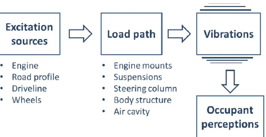
In order to study input excitations induced to the drivers/passengers, firstly it is necessary to identify the various excitation sources and analyse their main characteristics, i.e. the frequency bandwidth and the maximum amplitude in different modes of use. Typically, the main sources of vehicle vibrations are the wheels, the engine and the driveline [11].
Secondly, a load path analysis is performed, in order to understand how the generated vibrations “change” (amplification or damping phenomena) while going from the source to the receiver (driver and/or passengers).
This very important phase allows to understand how the main subsystems are involved in the filtering process and what is their contribution in the frequency response of the vehicle system [10, 17].
Finally, an analysis of tactile, visual and acoustic sensations that such vibrations generate on the occupants is performed, with the aim of understanding their impact on the subjective feeling of comfortable ride (figure 1.10).
With reference to the human mechanisms of perception (skin receptors, eyes, accelerations and ears), the mechanical vibrations are usually classified in the
33
frequency domain. All the vibrations with frequencies below 25Hz are perceived as mechanical vibrations, whereas the vibrations higher than 100 Hz are often perceived as noise. From 25 to 100 Hz the vibrations are perceived both as mechanical vibrations and as noise.
Figure 1.10: Main excitation sources and load paths for vehicle vibrations.
The term Primary Ride refers to all the vibrations of the car body at frequencies lower than 5 Hz. In this range the structural vibrations are negligible and the vehicle subsystems can be considered as rigid.
Instead, the term Shake indicates the medium frequency range vibrations from 5 to 25 Hz. This range is also named Secondary Ride. Harshness indicates the higher frequency vibrations, from 25 to 100 Hz. The structural vibrations are considered and usually perceived as Noise, which refers to all the vibro-acoustic phenomena above 100 Hz.
1.4. Role of modelling and simulation in the VDP
In recent decades, the VDP is being increasingly driven by complexity and multi-disciplinary nature of its products. Key goal remains the global vehicle performance
34
for multiple design attributes (passive safety, NVH, ride and handling, fuel economy), but new active and integrated solutions are being introduced, which broadens the design space to further improve the product quality, while meeting the ever increasing demands on safety and ecology.
For this reason, vehicle manufacturers have adopted a development strategy, in which the traditional, experience-driven “trial-and-error” approach has been supported increasingly by “Virtual Prototyping” techniques, based on Computer Aided Engineering (CAE) models. These tools can be used to predict and improve the vehicle (sub-)systems, from the concept phase onwards. CAE simulation and optimization techniques play a crucial role in the industrial development process of modern vehicles [7, 8, 18], due to their ability to manage and optimize efficiently complex and often conflicting sets of design criteria.
Well established 3D modelling techniques are available for structural linear and non-linear analyses (Finite Element Methods, FEM), for vibro-acoustic analyses (FEM + Boundary Element Methods, BEM), for aero- and thermo-dynamic analyses (Computational Fluid Dynamics, CFD), for dynamic simulation (Multi-Body Systems, MBS).
a) b) c)
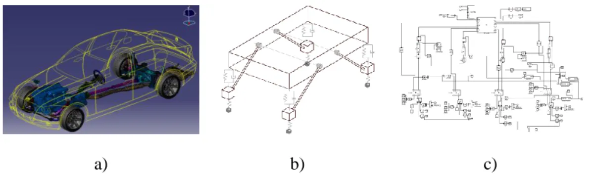
Figure 1.11: Example of vehicle 3D (a), 1D lumped parameters (b) and functional (c) models for vehicle ride and handling simulations.
These high-fidelity virtual models are developed during the detailed and refinement engineering phases, in order to validate the design choices before fixing them in a
35
physical prototype of the vehicle. An example of detailed MBS model for vehicle ride and handling simulation is shown in figure 1.11-a.
However, the limitation of 3D modelling methodologies is that accurate predictions can be achieved only when highly detailed geometric data become available, which has two main consequences on their applicability in the VDP:
3D models are not available in the initial design phases of a new product, when only general information can be derived from predecessor models, while most of the design decisions must still be taken;
after a detailed model is created, the feasibility of implementing design changes can be prohibitively low, because design constraints become fixed and subsystem designs become frozen; this has important consequences on the development process cost and on time-to-market of the product.
For these reasons, predictive tools and concept 1D simulation models are used during the upfront engineering phase, in order to improve initial CAD models making fast and effective design modifications.
In the field of vehicle engineering, two classes of 1D or concept modelling
techniques can be mentioned:
Physics-based models: these models have a reduced number of degrees of freedom (DOFs), with the components having a mathematical representation, which incorporates physical characteristics (like inertia, linear and non-linear stiffness, dissipative phenomena, etc.), lumped into a limited number of physical parameters (masses, springs, dampers, …). Bodies can be rigid or flexible; the mutual interaction and constraints is carried out by exchanging power, thus allowing that the behaviour of the system can be predicted with sufficient accuracy. An example is illustrated in figure 1.11-b, which shows a linearized lumped-parameter model of a vehicle for ride and handling simulations;
Functional models: these surrogate models provide a structured representation of functions (activities, actions, processes, operations) within the modelled system or the subject area (figure 1.11-c). Information on the behaviour of the system is derived through virtual or physical tests on predecessor models and
36
used to create analytical or numerical functional representations (polynomial regression, neural networks, data tables, maps, splines/surfaces matrices). All the functions are then interrelated by a flow block diagram, that graphically represents the system and the direction of information flow. Examples of 1D functional models in vehicle engineering are the kinematics & compliance (K&C) tables for suspension modelling, engine maps, modal reduced models of structural elements.
The availability of upfront engineering techniques is essential in the development of next-generation vehicles, but the applicability of state-of-the-art concept design methodologies must be expanded, by eliminating a number of limiting factors, like [19]:
a valid method for all problem categories is still missing;
there is a lack of comparative studies of available methodologies;
many modelling techniques have not reached maturity or have not yet been tested on industrial cases;
it is not an easy task to obtain, for each considered case, a good compromise between precision, simplicity, model size and similarity to the reference detailed 3D structure.
Some of these issues will be addressed in this dissertation.
1.5. The vehicle body concept modelling
Concept modelling methodologies are being recognized as an important part of the VDP. Their final objective is to reduce the time-to-market in manufacturing industry and to improve various functional performance attributes, like NVH, safety and energy efficiency of the vehicle. Each of these attributes is hard to improve in the last steps of the development process without raising conflicts with the others. For this
37
reason, many researchers have developed predictive concept CAE tools, which can be used to predict and improve the vehicle design from the concept phase onwards. A widely used classification divides these methods into three main categories [20]:
methods concurrent with CAD;
methods “from scratch”;
methods based on predecessor FE models.
These three groups will be explained in detail in the next sub-sections.
1.5.1. Methods concurrent with CAD
Methods belonging to this category aim at improving components as soon as CAD models become available for the various simulations. There are two main methods belonging to this category: the associative parametric CAE and the isogeometric
modelling methods.
The associative parametric CAE method
This method presents an approach based on an associative parametric modelling [1], which consists in the implementation of a functional architecture, based on the CATIA V5 framework [21]. This diagram is composed by a set of hierarchical levels of design data, with increasing level of detail. So, the designer can create the highest-level architecture in an early design stage and gradually populate the other lower levels when more CAD design knowledge becomes available.
The functional architecture is fully associative, so that at each design stage there is an analysis model with all available knowledge at that time. As shown in figure 1.12, each component is organized according to a “tree” structure. The design specification consists of two types of parameters: the derived published and the internal
38
parameters. The first represent a link to the specification parameters defined externally in the super-component, i.e. in the high level component. This ensures that all sub-components meet the basic idea of the super-component. Internal parameters are used for the component-internal use only. When some levels have been frozen, design iterations can then still be performed at the lower levels.
Figure 1.12: The associative parametric CAE method: composition of a single component [1].
The isogeometric modelling approach
This approach aims at defining an exact geometric model using basis functions generated from Non-Uniform Rational B-Splines (NURBS) [22].
39
In order to obtain a particular level of accuracy, it is possible to refine the basis of this kind of geometric curves, useful to define accurately the objects shape, and/or elevate its order, without changing the geometry or its parameterization. Refinements are easily implemented and exact geometry is maintained at all levels, without the necessity of subsequent communication with a CAD description.
It is established that the basic functions are complete with respect to affine transformations, meaning that all rigid body motions and constant strain states are exactly represented.
This promises future analysis capability directly based on the CAD design, thus avoiding the tedious CAD-to-CAE transition. The method can be applied to predict various functional performance attributes, such as statics, normal modes and fluid– structure interaction. The reported cases concern academic structures but also complex real-life structures.
This technique may find future application for concept design purposes. Indeed, it can enable the creation of isogeometric models that incorporate the available design knowledge. Various parameters can be optimized to provide input for the initial CAD formulation.
One disadvantage of this method is that the approach is based on rather exact CAD data, that cannot be available for the entire structure. For this reason, this technique cannot easily provide early simulation predictions.
1.5.2. Methods “from scratch”
This category of concept modelling approaches aims at establishing a functional layout of various BIW components starting from a completely new vehicle structure. For this reason, requirements needed for this category are very complex and intricate. Principal methodologies belonging to this category are: the topology design
40
The topology design optimization method
Whit this method, it is possible to determine where material must be present within a predefined space, called admissible design space, in order to optimally satisfy specific design criteria for the structure (for example static stiffness or yield strength) and constraints (supports or joints) [23-24].
The admissible design space consists of a space filled by hexahedral elements, the so-called “voxel” mesh. The methodology provides an initial topology design as first optimization step, after which the algorithm decides for each of the voxels whether material must be removed or not.
The topologically optimized component has, however, rough transition elements, which must be smoothed and modelled to achieve a realistic design.
In the vehicle design process, topology optimization is applied to optimize the load path configuration for statics, NVH and crashworthiness.
The functional layout design method
By using this approach, the designer is able to predict the performance of the model, using a simplified concept model, consisting of beams, joints and panels, which represent the functional layout of the structure.
In the most common version [25], the basic project starts from a body topology concept, which consists of three basic parts: beams, joints and panels.
Beams are represented by thin-walled structural metal parts, with simplified shapes of cross-sections. Joints are simple channel profiles located where the beams meet. Panels are represented by coarse four-node quadrilateral shell elements.
The connections between components are modelled with rigid connection elements. The model is completed by adding lumped and distributed trim masses and defining appropriate boundary conditions and loads. This concept model can be used for size
41
optimization of vehicle body NVH performance, by changing parameters like shell thicknesses, cross-section beam areas, etc.
Often, beam and joint layout is created and then node locations are optimized, in order to improve the design [26], or other approaches are based on the definition of beam concept FE models, according to new styling lines [27]. Finally, also commercial software are available, like SFE Concept software [28], which allow creating concept models, starting from simple geometrical descriptions.
With these tools, designers can define models based on implicit parametrical descriptions of geometry and topology and then assemble various parts at every design stage, by using the built-in FE generator. Firstly, a set of base points and lines must be defined, in order to indicate the position of joints, beams and panel edges. Then, beam cross-sections are defined and assigned to the lines. Parametric joints between the beams are automatically created, the shell components are added, and finally a mesh is created to enable FE analyses. SFE concept model can be modified quickly by moving influence points, stretching or bending base lines and by changing cross-sections.
1.5.3. Methods based on predecessor FE models
This category includes mesh morphing and concept modification approaches, which are used to design a variant or incremental improvement of an existing vehicle model. They make use of a predecessor FE model to identify issues and to include possible countermeasures already in the initial CAD design of the new vehicle.
Mesh morphing
Mesh morphing [29] is a CAE technique that allows to modify an existing mesh, without the need for re-meshing and preserving model integrity and connectivity,
42
since, during the process, only node coordinates are changed. This method starts from a predecessor FE model to modify the grid locations in the mesh, without changing the element connectivity. When the predecessor mesh has been reshaped, it can be analysed to identify weak spots, so that countermeasures can already be included in the initial CAD design [18].
Two variants are distinguished: the direct or freedom morphing and the indirect or
control-box morphing. In the first, the designer acts directly on the mesh, using the
concept of control nodes, deformable nodes and fixed nodes. The drawback is that the morphing operations are not repeatable.
Instead, in control box morphing, it is possible to define control boxes that envelop the existing mesh, and morphing operations are defined on these control boxes. One can incorporate the feature lines of the predecessor FE model in the control box definition, so that the regularity of feature lines and the element quality are preserved after performing the morphing operations. This is particularly useful for crash models.
In figure 1.13, an application of the two methodologies in the morphing of a vehicle joint structure is shown.
a) b)
Figure 1.13: Application on a vehicle joint structure: freedom morphing (a) and box morphing approaches (b) [30].
43
Concept modification approaches for beam reduction
Static and dynamic behaviours of the full vehicle mainly influenced by the beams’ and joints’ stiffness and mass properties. So, Beam&Joint (B&J) concept modelling tools are essential for accurate front-loading engineering of the full vehicle.
Usually, the reduced beam modelling approach consists in replacing detailed 3D FE models of beam members with simplified 1D beam models, also referred to as equivalent 1D concept beams. Along each primary beam-member, a number of intersection planes are defined, corresponding to portions of the beam with almost constant cross-section shape. Mass and stiffness properties of these beams are computed by applying proper analytical or numerical procedures to a set of cross-sections; for each of these, equivalent beam properties are computed.
Once properties of beam segments are determined, equivalent 1D beam elements replace detailed beam-like structures. The entire beam member can be then represented as a series of linear beam elements, using a standard FE library. An example is shown in figure 1.14, where both the original detailed and the simplified FE model of B-pillars of a vehicle BIW are represented.
Several methods can be mentioned, briefly described below.
a) b)
Figure 1.14: Replacement of original (a) with concept model (b) of BIW B-pillars [31].
![Figure 1.9: First torsional global mode for a concept BIW for passenger car [16].](https://thumb-eu.123doks.com/thumbv2/123dokorg/2876107.9866/34.892.271.645.251.526/figure-torsional-global-mode-concept-biw-passenger-car.webp)
![Figure 1.12: The associative parametric CAE method: composition of a single component [1]](https://thumb-eu.123doks.com/thumbv2/123dokorg/2876107.9866/40.892.292.627.346.794/figure-associative-parametric-cae-method-composition-single-component.webp)

![Figure 2.2: Frequency variations between each spot-welded model and the reference model [57]](https://thumb-eu.123doks.com/thumbv2/123dokorg/2876107.9866/63.892.158.755.133.476/figure-frequency-variations-spot-welded-model-reference-model.webp)
![Figure 2.3: First (a), second (b) and third (c) vibration modes in the lateral (x-z) flexural plane [57]](https://thumb-eu.123doks.com/thumbv2/123dokorg/2876107.9866/64.892.165.761.792.952/figure-second-b-vibration-modes-lateral-flexural-plane.webp)
![Figure 2.4: First (a), second (b) and third (c) vibration modes in the vertical (x-y) flexural plane [57]](https://thumb-eu.123doks.com/thumbv2/123dokorg/2876107.9866/65.892.150.770.131.287/figure-second-b-vibration-modes-vertical-flexural-plane.webp)

