Università Politecnica delle Marche
Scuola di Dottorato di Ricerca in Scienze dell’Ingegneria Corso di Dottorato in Ingegneria Industriale
---
Physical modelling of the high
temperature deformation of complex
microstructure materials for aeronautical
applications
Ph.D. Dissertation of:
Mohamed Saad Ghat
Supervisor:
Prof.Ing. Stefano Spigarelli
Ph.D. Course coordinator:
Università Politecnica delle Marche
To my parents,
Eng.Saad Shehata Ghat & Mrs.Fatma El-Zahra M.Khalil For what you’ve been
&
what you’ve done
To:
My sister “Fatma El-Zahra Ghat” and my brother “Dr.Amr Ghat” My uncle “Mr.Moustafa M.Khalil” and “Dr.Metwaley shehata Ghat” My beloved late grandparents “Shehata Ghat” and “Mohamed Khalil”
Acknowledgements
Firstly, I would like to express my sincere gratitude to my advisor Prof. Ing. Stefano Spigarelli. for the continuous support of my Ph.D study and
related research, for his patience, motivation, and knowledge, for providing me an opportunity to join the team as intern, and who gave access to the laboratory and research facilities, and for his guidance helped me in all the time of research and writing of this thesis.
Beside my advisor, my sincere thanks also go to Prof. Marcello Cabibbo, for his support and guidance during my research. Also, I am particularly
grateful to Prof. Maria Cecilia Poletti at Graz university of Technology, Austria, for her time and academic support during the stay period in Graz. I am grateful to Prof. M. El Mehtedi for his efforts, helpful and inspiring on the torsion tests activities.
I also want to thank all the technical staff who have helped me and offered
their technical assistance to carry out my experimental work, especially Daniele Ciccarelli.
I thank all my friends and colleagues, past and present, whether discussing work at the University, especially Chiara Paoletti, Dagmawi Neway and Ahmed S.Afify, for their friendship and sharing a scientific and general ideas. Finally, I reserve heartfelt thanks to my parents, I cannot express gratitude in words to my father, mother, brother and sisters who have fully supported me and encouraged me to reach the finish line. Thanks to My late grandparents.
“The important thing is to not stop questioning. Curiosity has its own reason for existing.”
“Life is like riding a bicycle. To keep your balance, you must keep moving.” Albert Einstein (1879 –1955)
“Resist What You Love .... And Bear What You Hate.” Mustafa Mahmoud (1921–2009)
Abstract
Today aerospace industry is growing fast on developing the mechanical component for the hot section part of the jet engine. The prediction of the dynamic behavior of metals is usually investigated by phenomenological models. In this study, we described the hot deformation behavior by using different approaches for constitutive model: Hansel and spittle equation, Garofalo equation and basic modelling. In the present PhD work, three different metals were used (Inconel 718, Ti-6Al-4V and AA2024 – T3) which are extensively used in the aerospace industry. A basic model was applied to pure Ni and then to a single-phase superalloy. In the case of Ti-6Al-4V alloy, the hot deformation behavior was studied by hot compression test in β phase domain. The effects of hot deformation parameters (deformation temperature and strain rate) on flow stress were analyzed. A phenomenological model based on the Hansel and Spittel equation was used to obtain a quite accurate description of the flow curves for processing temperatures between 1010 and 1150 ºC and strain rates of 100 and 0.001 s-¹. The model used gave an accurate excellent experiments result. The high temperature deformation of the
superalloy, a solution treated IN718, was investigated by torsion testing in a high-temperature regime (1000–1100 °C). The peak-flow stress dependence
on strain-rate and temperature was described by a physically-based constitutive equations, which took into account both dislocation hardening and solid solution strengthening, and represents a substantial advancement over phenomenological models, although, in the present form, it cannot give the full shape of the flow curves.
The creep response for AA2024-T3 alloy produced by a friction stir processing (FSP) has been investigated, the same creep modeling based on the theoretical approach. The hardness variation with creep duration was used to quantify the particle strengthening term.
Table of Contents
Acknowledgements ... ii Abstract ... iv List of Figures ... ii List of Tables ... v Chapter 1 – Introduction ... 1 1.1. Thermomechanical Modelling ... 1 1.2. Project Aims ... 3 1.3. Thesis Outline ... 3Chapter 2 – Literature Review ... 6
2.1. High Temperature Materials ... 6
2.2. The need for high-temperature materials ... 7
2.3. Operating environment ... 9
2.4. Constitutive descriptions for metals and alloys in hot working ... 13
2.4.1. Arrhenius equation ... 15
2.5. The material for high temperature application: what is the superalloy? ... 19
2.5.1. Classification of superalloys ... 19
2.6. Application of Superalloys ... 24
2.7. Physical metallurgy of nickel and its alloys ... 25
2.8. Inconel 718: Features and characterization ... 29
2.9. Workability and hot deformation behavior of IN718 ... 31
2.10. Titanium Alloys ... 35
2.10.1. Classification of titanium alloys ... 37
2.11. Ti-6Al-4V features and characterization ... 41
2.12. Workability and hot deformation behavior of Ti-6Al-4V ... 43
2.13. Aluminum and Aluminum Alloys ... 45
2.13.2. Wrought Alloy Classes ... 47
2.14. Hot deformation and creep of Aluminum alloys ... 52
2.15. Conclusions ... 52
Chapter 3 - Constitutive Modeling On β Transus of Ti-6Al-4V Alloy at High Temperature and Strain Rates ... 55
3.1. Introduction ... 55
3.2. Compression test ... 56
3.3. Experimental Procedure ... 58
3.4. Experimental results for Ti – 6Al – 4V ... 59
3.4.1. Peak flow stress dependence on strain rate and temperature. .... 59
3.4.2. Flow stress variation with strain, strain rate and temperature .... 63
3.5. Summary and Conclusions ... 70
Chapter 4 - A model for the Hot Workability of Solution Treated IN718 Superalloy ... 72
4.1. Torsion test ... 72
4.2. Test device ... 73
4.3. Evaluation methods ... 75
4.4. Experimental results for IN 718 ... 77
4.5. Effects of solid solution strengthening ... 83
4.6. Material models ... 85
4.6.1. Constitutive analysis ... 85
4.7. Microstructure analysis ... 87
4.8. Basic creep modelling of Nickel and single-phase Ni based superalloy ... 91
4.9. Description of pure Nickel ... 96
4.10. Description of IN718 solutioned alloy ... 102
4.11. Summary and Conclusions ... 109
Chapter 5 - Physical Modeling of The Creep Response for Al-Cu-Mg Alloy Produced by Friction Stir Processing ... 111
5.2. Creep and Creep testing ... 113
5.2.1. Phenomenological laws and coefficients ... 117
5.3. Experimental procedure for AA2024-T3 ... 121
5.4. Results for AA2024-T3 ... 124
5.4.1. Microstructure evaluation during creep ... 124
5.5. Creep data ... 136
5.6. Creep modelling of AA2024-T3 ... 139
5.7. Summary and Conclusions ... 149
Chapter 6 - Conclusions ... 151
List of Figures
Chapter 2
Figure 2.1: Typical operating temperatures in high-temperatureenvironments[2]. ... 8
Figure 2.2: Stress/temperature regimes of high-temperature materials[2]. 11 Figure 2.3: Specific strength comparison of high-temperature alloys [2]. .. 11
Figure 2.4: Typical 0.1% / 100h creep strength for various titanium alloys [2]. ... 12
Figure 2.5: (a) Typical true stress–strain curves for 42CrMo steel under the different deformation temperatures with strain-rate of 0.01s-1; (b) typical flow stress curve [8]. ... 14
Figure 2.6: Comparisons between predicted and measured flow stress curves of 42CrMo steel under strain-rates of (a) 0.01s-1 and (b) 50s-1[12]. ... 18
Figure 2.7: Tensile strength of superalloys at different temperature ranges[16]. ... 23
Figure 2.8: Cross section of the Rolls-Royce jet engine (extensive use of nickel-based superalloys in the combustor and turbine sections)[1]. ... 25
Figure 2.9: Face Centered Cubic (FCC) crystal structure[16]. ... 26
Figure 2.10: Representation of different alloying elements present in Ni base alloys[16] . ... 26
Figure 2.11: The unit cell of γ′′ precipitate[16] . ... 28
Figure 2.12: Stress-rupture characteristics of wrought Ni-, Fe-Ni- and Co- based superalloys depending on the strengthening mechanism[3]. ... 31
Figure 2.13: The true stress–true strain curves of IN718 at various strain rates: (a) ε̇=0.001 s−1, (b) ε̇=0.01 s−1, (c) ε̇=0.1 s−1, (d) ε̇=1 s−1[28]. ... 33
Figure 2.14: The dependence of the peak stress on strain rate at different temperatures: (a) ln σp versus ln ε̇, (b) σp versus ln ε̇ (c) ln(sinh(ασp)) versus ln ε̇.[28]. ... 34
Figure 2.15: ln(sinh(ασp)) versus 1/T [28]. ... 35
Figure 2.16: Titanium usage in the aero-engine[4]. ... 36
Figure 2.17: Crystal structure of hcp α and bcc β phase[4]. ... 37
Figure 2.18: Influence of alloying elements on phase diagrams of titanium alloys[4]. ... 38
Figure 2.19: Schematic quasi-vertical section for ternary titanium alloys containing both α and β stabilising solute elements [4]. ... 39
Figure 2.20: A schematic illustration of microstructures occurring in
Ti-6Al-4V after quenching from different temperatures [4]. ... 42
Figure 2.21: Flow curves obtained at 1000 °C (a), 1050 °C (b), 1100 °C (c)
at different strain rates [44]. ... 44
Figure 2.22: Relationships among commonly used alloys in the 2xxx
series (Al-Cu)[5]. ... 48
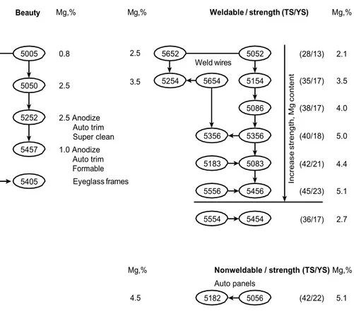
Figure 2.23: Relationships among commonly used alloys in the 5xxx series
(Al-Mg). Tensile strength (TS) and yield strength (YS) are in ksi unit[5]. . 49
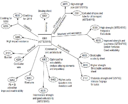
Figure 2.24: Relationships among commonly used alloys in the 6xxx series
(Al-Mg-Si).Tensile strength (TS) and yield strength (YS) are in ksi units[5]. ... 50
Figure 2.25: Relationships among commonly used alloys in the 7xxx series
(Al-Zn-Cu-Mg-Cr).Tensile strength (TS) and yield strength (YS) are in ksi units[5]. ... 51
Chapter 3
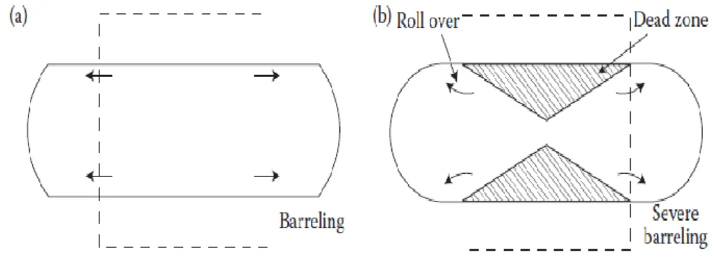
Figure 3.1: (a) slight barreling as a result of light friction which hinders
sliding and (b) severe barreling as a result of high friction which prevents slipping[48]. ... 58
Figure 3.2: Double cone specimens before and after the compression test for
(Ti64). ... 59
Figure 3.3: Representative stress-strain high temperature flow curves of the
Ti – 6Al – 4V alloy under different compression deformation conditions: (a) 1050°C; (b)1150°C. ... 60
Figure 3.4: Strain rate dependence on the peak flow stress with α = 0.0154
MPa-1. ... 61
Figure 3.5: Plot used to calculate the activation energy, ln [sinh (ασ)]
vs 1/T. ... 62
Figure 3.6: The relationships between the peak stress and the
Zener-Hollomon parameter for the calculated peaks; compression test. ... 63
Figure 3.7: Comparison between the modelled flow curves and experimental
data at 0.1 s-1. ... 65
Figure 3.8: Comparison between the modelled flow curves and experimental
data at 1 s-1. ... 66
Figure 3.10: Comparison between the modelled flow curves and
experimental data at 50 s-1. ... 68
Chapter 4
Figure 4.1: typical torsion‐test specimen[71] ... 72
Figure 4.2: Servo controlled, hydraulic torsion test machine. ... 74 Figure 4.3. Torsion of solid bar specimen[80]. ... 75 Figure 4.4: Specimen for torsion testing and experimental layout for torsion
testing. ... 79
Figure 4.5: Representative flow equivalent-stress vs equivalent strain flow
curves obtained by testing the IN718 in torsion. ... 80
Figure 4.6: Peak flow stress in torsion as a function of the testing strain rate.
... 81
Figure 4.7: Strain-hardening rate ( = ) as a function of flow stress
for representative conditions. The Figure also plots the peak stress (σp) and the saturation stress(σs*). ... 82
Figure 4.8: Comparison between the peak flow stress values obtained by
testing in torsion single-phase IN718 (this study) and pure-Ni in torsion and compression at 1000 and 1100°C[61][86]... 84
Figure 4.9: Strain rate as a function of sinh(σp), with =0.003.
... 86
Figure 4.10: Calculation of the activation energy for hot working of
single-phase IN718. ... 86
Figure 4.11: Zener-Hollomon parameter as a function of sinh(σp) ... 87
Figure 4.12: Microstructure of the received alloy (IN 718), heat treatment
1150 ºC for 4 h (Light optical microscopy), before a hot torsion deformation. ... 88
Figure 4.13: Optical images of the IN718 alloy microstructure deformed at:
(a) 1100 ºC ,1 s-¹; (b) 1100 ºC, 0,01 s-¹; (c)1000 ºC; 1 s-¹; (d) 1000 ºC,0, 01 s-¹. ... 91
Figure 4.14: Peak-flow stress in pure Ni[61]. The curves were calculated by
the model equation described in Section 3.6, with G=(93x104 -36T)[MPa][96],Rmax=570 MPa (=1.5RUTS), D=DNi=2x10⁻⁴exp(290/RT) [m2s -1][97],U
Figure 4.15: Plot of the Kσ term as a function of σd /RUTS for p=2 and q=1, or p=1and q=0.5. The boxed area represents the interval of activation energy values obtained in[61]. ... 98
Figure 4.17: a) Peak-flow stress in pure Ni by compression testing[86]; b)
steady state creep rate a function of applied stress[98]. The model curves were calculated as in Figure 4.15. ... 101
Figure 4.18: Plot of the drag stress as a function of applied stress for
Al-2%Mg[87]. The curves obtained at different homologous temperatures overlap on a straight line in the low stress regime. ... 103
Figure 4.19: Peak flow stress as a function of the strain rate for solution
treated IN718 (G=(93x104-36T) [MPa][96], R
max=1215 MPa (=1.5RUTS),D=DNi=2x10⁻⁴exp(290/RT) [m2s-1][97], Uss=30 kJ mol-1, σss=0.37σ, p=1, q=0.5 and CL=86 ... 105
Figure 4.20: Peak flow stress as a function of the strain rate for 1050°C-
1 h solution treated IN718[99], with (G=(93x104-36T) [MPa] [96], Rmax=1215 MPa (=1.5RUTS), D=DNi=2x10⁻⁴exp(-290/RT) [m2s-1][97], Uss=30 kJ mol-1, σss=0.37σ , p=1, q=0.5 and C
L=86 ... 106
Figure 4.21: Variation of the ultimate tensile strength with solution treatment
temperature, for a standard duration of 1h (data from[90]). ... 108
Chapter 5
Figure.5.1: Schematic of a creep test[108]. ... 115 Figure.5.2: Constant true stress (a) and constant strain rate (b) creep behavior
in pure and Class M (or Class I) metals[48]. ... 115
Figure 5.3: Stress and temperature dependence of the steady state creep
rate[110]. ... 118
Figure 5.4: Schematic drawing of a) friction stir processing processand b)
tool[113]. ... 123
Figure 5.5: Schematic drawing of the Creep specimen[101]. ... 123 Figure 5.6: Microstructure of the FSP 2024-T3 alloy: a) optical micrograph;
b) structure observed by TEM. ... 126
Figure 5.7: Vickers hardness variation along the thickness of the FSP
2024-T3 alloy, measured in the center of the FSP zone. The broken line represents the average HV value. ... 127
Figure 5.9: Hardness variation as a function of the temperature-compensated
time, with Q = 260 kJ mol-1. The data substantially overlap on the same sigmoidal curve. The Figure also shows the hardness value for the T3 state, for the alloy after FSP, and for the fully annealed condition[118]. ... 130
Figure 5.10: Representative TEM micrographs of the sample tested under
140 MPa at 250°C. (a) The presence of large intergranular precipitates is well documented; (b), an example of the fine intragranular particles is shown. 131
Figure 5.11: Representative TEM micrographs of the sample tested under
100 MPa at 250°C. ... 132
Figure 5.12: Representative TEM micrographs of the sample tested under 30
and 50 MPa at 250°C... 134
Figure 5.13: Distribution of the secondary phase particle length, of the
samples tested under 30, 100, and 140 MPa at 250°C. ... 135
Figure 5.14: Representative TEM micrograph of the sample tested under 25
MPa at 315°C. ... 136
Figure 5.15: Minimum creep rate dependence on applied stress for 2024-T3
FSP alloy, tested both in constant (CLE) and variable (VLE) load conditions. The Figure also shows the strain rate for the base alloy tested by CLE (broken curves). ... 137
Figure 5.16: Zener-Hollomon parameter as a function of applied stress for
2024-T3 FSP tested under constant load conditions. ... 138
Figure 5.17: Particle (Orowan) strengthening term as a function of
temperature compensated testing time. ... 145
Figure 5.18: Reciprocal of particle spacing as a function of the Orowan stress
at room temperature. ... 146
Figure 5.19: Basic creep modelling of the minimum strain rate dependence
List of Tables
Chapter 2
Table 2.1: Temperature capability of high-temperature material systems [2].
... 10
Table 2.2: Mechanical properties depending on temperature for selected
Fe-, Ni- and Co based superalloys[3][16]. ... 30
Table 2.3: Standard Terminology and Principle Alloy Element of Aluminum
Alloy [5] ... 46
Table 2.4: Aluminum Alloy Series Designation of Casting Alloys [5] ... 47
Chapter 3
Table 3.1: Chemical composition of the Ti6Al4V used in this study (in wt.%)
... 59
Chapter 5
Table 5.1: chemical composition of AA2024-T3 (wt.%)[101] ... 122 Table 5.2: Summary of the experimental results. The strain rate values
Chapter 1.
Introduction
1.1. Thermomechanical Modelling
Flow behavior of the metals during hot forming process is often complex. The hardening and softening mechanisms are both significantly influenced
by many factors such as strain, strain rate, and forming temperature. A given combination of thermo-mechanical parameters yields a particular
metallurgical phenomenon (microstructure evolution); on the other hand, microstructure changes of the metal during the hot forming process in turn affect the mechanical characteristics of the metal such as the flow stress, and hence influence the forming processes.
Understanding the flow behaviors of metals and alloys at hot deformation condition has a great importance for designers of metal forming processes (hot rolling, forging and extrusion) because of its effective role on metal flow pattern as well as the kinetics of metallurgical transformation (for example, static, dynamic, and metadynamic recrystallization behaviors).
In the industrial practice with the help of the FEM simulation, the distribution of stress and strain during the deformation can be analyzed
To obtain accurate simulations and good results, the materials flow stress has to be determined in reliable basic experiments. Some tests like torsion tests, compression tests, etc. have been developed with the aim to characterize the materials flow stress.
The constitutive models are the mathematical representation of the flow behavior of materials, which used to describe the plastic flow properties of the metals and alloys, which are divided into three categories, including the phenomenological and physically-based models, and descriptions by artificial neural networks. The constitutive models are used as input to FE code for calculating the material’s response under determinated loading conditions. The success of the numerical simulation to accurately reproduce the flow behavior, depends on how accurately the constitutive equation represent the deformation behavior of the metals.
Nonetheless, numerical simulations can be truly reliable only when a proper constitutive model is built. Therefore, based on the experimentally
measured data, a number of research groups have made efforts to develop constitutive equations to describe the hot deformation behaviors of metals and alloys. in meanwhile a number of constitutive models have been proposed or modified in recent years to describe the strain rate, stain and temperature-dependent flow behavior of metals and alloys. These models all show that increasing the strain-rate and decreasing the temperature can both enhance the resistance of plastic deformation and cause a rise of the flow stress. For the original constitutive models, there are always some limitations when the authors firstly proposed for their studied materials.
1.2. Project Aims
The aim of this thesis is to investigate the prediction of the dynamic behavior of metals by using a constitutive model (basic creep modelling, Hansel and spittle equation and Garofalo equation), in order to describe the hot deformation behavior. For this purpose, three different metals were considered: The Inconel 718 (age -hardenable nickel-based super alloy), the Titanium Ti-6Al-4V and the commercial AA2024-T3/ Al-Cu-Mg 2024 aluminum alloy. In order to investigate the mechanical response of these metals in dynamic conditions, different experimental techniques were
developed and used, microstructural analysis is performed. The experimental data were analyzed through different procedures with the
aim to provide consistent methodologies suited to extract sets of model parameters.
1.3. Thesis Outline
Chapter 2 is a review of the literature discussing the metallurgical
background of IN 718 Superalloy, titanium (Ti-6Al-4V.) and AA2024-T3 aluminum alloys which included: applications, alloy classification, features and characterization of each alloy, workability and hot deformation behavior.
Chapter 3 discusses the constitutive modeling on the β transus of
Ti-6Al-4V alloys at high temperatures and strain rates. The hot compression test was used to investigate the high temperature deformation.
Hensel and Spittel equation was used, peak-flow stress dependence on temperature and strain rate are discussed using a classic phenomenological approach (Garofalo and Arrhenius equations). This Chapter thus outline ones of the classical phenomenological approaches commonly used to describe the high temperature response of advanced materials.
Chapter 4 discusses the hot workability of solution treated for IN718
superalloy. A basic model was applied to pure Ni and then to a single-phase superalloy. Hot torsion tests were used to investigate the high temperature deformation of the superalloy and a solution treated IN718. An alternative physically-based approach, developed for creep of fcc metals, was used for a pure Ni and then to a single-phase superalloy. Microstructure characterization of the torsioned samples, dislocation hardening and solid solution strengthening are all discussed.
Chapter 5 discusses the physical modeling of the creep response for the
AA2024-T3 aluminum alloy produced by friction stir processing (FSP). The same constitutive model based on a theoretical approach have been
discussed to describe the creep response of this multi-phase material. Microstructural evolution during creep, hardness variation with creep duration, creep rate dependence on applied stress at steady state and the dislocation mobility M are all discussed.
Chapter 2.
Literature Review
This chapter begins with an introduction to the high temperature materials (IN718, titanium and its alloys and Aluminum alloys), that were the subjects of this work. Features and characterizations, workability and hot deformation behavior for each alloy has been discussed. The second section discusses the constitutive descriptions for metals and alloys in hot working.
2.1. High Temperature Materials
The subject of high temperature materials is a very broad topic indeed. When a material is used at elevated temperatures, its strength, as reflected in tensile strength, stress rupture life, or fatigue life, is of prime importance.
It is also likely that corrosion processes affect strength; therefore, high temperature corrosion resistance is critical. The most demanding
applications for high temperature materials are found in aircraft jet engines, industrial gas turbine and nuclear reactor. However, many furnaces, ducting
and electronic and lighting devices operate at such high temperature. High temperature materials are mainly used in aircraft engines components,
where Ti and Ni based super alloys are important materials to be used for manufacturing the blades and disks[1][2].Their excellent mechanical properties, even under extreme conditions, come from their two-phase optimized microstructures.
Refractory metals have high strengths at 1200 °C, but oxidation resistance is poor[1][2]. Nickel and cobalt base superalloys have good strengths up to 1000°C with reasonable oxidation resistance[3]. Titanium alloys and some steels can be used to temperatures of about 600 to 700°C[4], Aluminum alloys cannot be subjected to high loads at temperatures much above about - 200°C, but fiber-reinforced aluminum has flexural strengths as high as 300 to 400 MPa at 300°C [5].
2.2. The need for high-temperature materials
High-temperature technology is of major importance in many industries including primary metal and nonmetal production, material processing,
chemical engineering, transportation and power generation. For many of these industries the price of fuel is a major component of overall operating
costs. Materials that allow operation at high temperature are essential for industrial competitiveness because the efficiency of fuel conversion and use is related to operating temperature. Current operating temperatures in various applications are shown in Fig. 2.1, together with the melting temperatures of selected materials [2]. However, no material is capable of operating approximately above 4000°C and thermal ablation must be used at these temperatures. Many industries could benefit from still higher operating temperatures. The temperature of super heater tubes for steam-raising boilers in power plants is currently 560 °C; if this could be increased to 650 °C, efficiency would increase from 35% to 36.5%. This would result in a saving approximately 3.5 x 10 6 ton of coal per year, i.e. 4% of the total
in diesel engine development in the United States has allowed higher operating temperatures, thus improving efficiency (an increase from 38% to 65% appears possible) and reducing exhaust pollution. Higher temperature operation has a powerful effect on the performance of the gas turbine engine. For example, an increase of 150 °C in turbine entry temperature combined with elimination of internal air cooling of turbine components can give an improvement of around 6% in gas generator thermal efficiency. This order of benefit led to the progressive development of nickel superalloys for gas turbine applications and more recently led to the search for materials with higher temperature capability than the superalloys [1][2].
Figure 2.1: Typical operating temperatures in high-temperature
2.3. Operating environment
High-temperature materials operate in environments with a wide spectrum of mechanical and chemical conditions. The temperature may be relatively constant (e.g. in continuously operated heat-treatment furnaces) or subject to severe cycling (e.g. in jet engines where the thin edges of turbine blades
can experience temperature changes of more than 1000 °C in seconds). The operating stress can vary from very low stress levels in furnace heating
elements, for example, to high combined centrifugal and thermal stresses in a gas turbine disc [1][2]. Some measure of inherent oxidation resistance
is an essential characteristic of high-temperature materials; however, many applications involve significantly more complex corrosive environments than simple oxidation. In certain types of coal gasification, the atmosphere may be reducing to some extent; thus, alloys that rely on chromium oxide scales for protection do not perform as well as aluminum oxide forming alloys. Oxidation is further modified by atmospheric and fuel contaminants as in, for example, the use of lower grade fuel such as residual fuel oil, instead of higher fractions such as kerosene, in industrial turbines, and boilers. The lower grade fuels contain larger amounts of impurities such as vanadium, Sulphur and sodium which accelerate corrosion. Erosion is an important factor in applications such as fluidized-bed coal combustion. The required life can range from minutes for rocket motor, through 50000 to 100000h for industrial steam and gas turbines, to more than 20 y for large steam turbine installations. Operational stress has a major influence on temperature capability, with the limit being 0.7 to 0.9 of the melting
applications Table 2.1. On the basis of the Tu, / Tm factor, aluminum alloys can be considered as high-temperature alloys. Although they can operate up
to 300 °C, compared with 580°C for low-alloy steels, this represents a Tu, / Tm factor of 0.45 compared with 0.37 for low alloy steels. The broad
stress-temperature operational regimes of various materials in stressed applications are illustrated in Fig. 2.2[2]. The strength is based on the 0.2% proof stress for metals and an appropriate proportion of the flexure strength for ceramics and composites. Specific strength Fig. 2.3[2] is an important property in materials for rotating machinery [1][2].
Table 2.1: Temperature capability of high-temperature material systems
[2].
Material Approx. max. use temp., Tu (°C)
Tu/Tm cApplication Aluminium (RR350) 300 0.45 Stressed
Low-alloy steel 580 0.37 Stressed
Austenitic steel (A286) 600 0.4 Stressed
Nickel superalloy
(MarM002) 1000 0.77 Stressed
Nickel (Brightray H) 1250 0.9 Unstressed
Alummina 1850 0.9 Unstressed
Figure 2.2: Stress/temperature regimes of high-temperature materials[2].
The superior specific strength of titanium relative to steel and nickel superalloys provided the motivation for its development for aerospace applications. Major progress has been achieved in increasing the temperature capability of titanium alloys. A recent alloy, IMI829, can be used up to 600 ~ some 250 ~ higher than the early Ti 6-4 alloy Fig. 2.4[2] Despite the fact that the Tu / Tm factor for IMI829 of 0.36 is similar to that for low-alloy steel[1][2].
Figure 2.4: Typical 0.1% / 100h creep strength for various titanium alloys
2.4. Constitutive descriptions for metals and alloys in
hot working
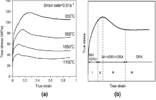
Flow behavior of materials under the hot deformation process is a very complex affair. Many factors such as strain, strain rate and deformation temperature significantly influence the hardening and softening mechanisms. During hot deformation, the microstructure changes, and this in turn affects the mechanical response of the material. Understanding the flow behaviors of metals and alloys at hot deformation condition has thus, a great importance for designers of metal forming processes (hot rolling, forging and extrusion) because of its effective role on metal flow pattern as well as the kinetics of metallurgical transformation[6][7].The flow properties of the metals and alloys are described by the constitutive relations that can be used in a computer code to model the forging response of mechanical part members under prevailing loading conditions. So, the numerical simulations can be truly effective only when a proper constitutive model is built. Therefore, much work was done by many researchers to develop reliable constitutive equations, to describe the hot deformation behaviors of metals and alloys. Fig.2.5 a. shows the typical true stress strain curves obtained from the hot compression of 42CrMo steel[8]. The figure shows that the effects of the temperature and strain-rate on the flow stress are significant for all the tested conditions. At small strains, the true stress strain curves exhibit a peak stress (σpeak), while the stress level decreases
with increasing deformation temperature and decreasing strain rate (έ). The flow curves obtained from experiments consist of four different stage,
as shown in Fig. 2.5b[8]. stage I (Work hardening stage), stage II (Transition stage), stage III (Softening stage) and stage IV (Steady stage) [8] .
Figure2.5: (a) Typical true stress–strain curves for 42CrMo steel under the
different deformation temperatures with strain-rate of 0.01s-1;
(b) typical flow stress curve [8].
Some constitutive models have been modified, to describe the strain rate, strain, temperature and flow behavior of metals and alloys. The constitutive models are divided into three categories [9][10][11]:
1. Phenomenological constitutive models. They consist of some
depending on empirical observations. So, this kind of model is used in a limited applications fields which covering the limited ranges of strain rate
and temperature and they exhibit the reduced flexibility. Yet, since phenomenological models are easy to handle, still form the backbone of the libraries of material properties in FEM codes[12].
2. Physical-based constitutive models. This type of model takes into
account the physical aspects of material behaviors. The majority of the models are based on the thermally activated dislocation movement theory. Compared to the phenomenological model, they allow an accurate definition of material behavior under wide ranges of loading conditions with some physical assumptions and large number of the material constants. In addition, they are reasonably affective for simple microstructures, but become increasingly complex for alloys in which several micro mechanisms coexist, which is the normal case in practice[12].
3. Artificial neural network (ANN). This approach solves the problems
that are very difficult to solve by a normal methods. Therefore, it can provide a different approach for materials modeling than a statistical or numerical method[12].
2.4.1. Arrhenius equation
The Arrhenius equation is widely used especially at high temperature to describe the relationship between the strain rate, flow stress and temperature. The effects of the temperatures and strain rate on the deformation behavior can be then represented by Zener–Hollomon
The hyperbolic law in Arrhenius type equation gives better approximations between Zener–Hollomon parameter and flow stress.
έ = 𝐴𝐹(𝜎) exp (− 𝑄𝐻𝑊 𝑅𝑇 ) (2.1) 𝑍 = 𝜀̇exp ( 𝑄𝐻𝑊 𝑅𝑇 ) (2.2) έ = 𝐴 1𝜎 𝑛′exp (– 𝑄𝐻𝑊 𝑅𝑇 ) (𝛼𝜎 < 0,8 ) (2.3) έ = 𝐴 2 exp(βσ) exp (– 𝑄 𝐻𝑊 𝑅𝑇 ) (𝛼𝜎 > 1,2) (2.4) έ = A [Sinh (α σ)] n exp (– 𝑄 𝐻𝑊 RT ) (all) (2.5)
where έ is the strain rate (s−1), R is the universal gas constant (8.3145 J mol−1 K−1), T is the absolute temperature (K), and Q is the activation energy of hot deformation (J mol−1), A, n′, β and n are the materials constants. α is stress multiplier, MPa-¹ defined as α = β/n′ for all stress level. Eq. (2.1) can be represented as shown in Eq.2.5. Then, the flow stress σ can be written as a function of Z parameter, considering the definition of the hyperbolic law given as,
𝜎 = 𝛼1ln [(𝑧𝐴) 1/𝑛+ [(𝐴𝑧) 2/𝑛+ 1]1/2] (2.6)
The lower the Zener–Hollomon parameter is, the larger the extent of flow softening becomes. Moreover, the higher the Zener–Hollomon parameter, the lower the power dissipation rate is. Flow instability occurring under high
In the recent years, investigations [13][14][15] established the flow behavior of different metals and alloys during hot deformation by the Arrhenius equation. Lin et al.[6],for example, revised the models to describe the flow behaviors of 42CrMo steel over wide range of forming temperatures and strain-rates by compensation of strain and strain-rate. They found that the values of Q, A, n and α should be expressed as polynomial functions of strain, Eq.2.7.
Q = E0 + E1 ε + E2 ε2 + E3 ε2+E4 ε2+E5 ε2
α = C0 + C1 ε + C2 ε2 +C3 ε2 + C4 ε2 + C5 ε2 (2.7) n = D0 + D1 ε + D2 ε2 +D3 ε2 + D4 ε2 + D5 ε2
ln A = F0 + F1 ε + F2 ε2 +F3 ε2 + F4 ε2 + F5 ε2
In order to accurately predict the flow behavior of the 42CrMo steel, the Zener–Hollomon parameter should be compensated by multiplying both sides of Eq. (2.2) by ε˙1/3. Then, the modified Zener–Hollomon parameter, Z′, can be expressed as,
Z′= 𝜀̇4/3 exp ( 𝑄𝐻𝑊 𝑅
𝑇 ) (2.8)
Fig. 2.6 [12] shows the comparisons between predicted and measured flow stress curves of 42CrMo steel. It can be easily found that the proposed deformation constitutive equations can gives an accurate and precise estimate of the flow stress for 42CrMo steel, and can be used for the analysis
Figure 2.6: Comparisons between predicted and measured flow stress
curves of 42CrMo steel under strain-rates of (a) 0.01s-1 and (b) 50s-1[12].
The proposed modifications by Lin et al.[6] was verified by Mandal et al. [15] and Samantaray et al. [14]. Mandal et al.[15] modified the material constants by incorporating fourth-order polynomial function of strains, and their model can accurately predict the high-temperature flow stress of a Ti-modified austenitic stainless steel. Samantaray etal [14].modified them with third-order polynomial function of strains, and their modified constitutive model is effective for describing the high-temperature flow behaviors of modified 9Cr–1Mo (P91) steel. In addition, this modification method by strain compensation is also useful for the aluminum alloy [13].The examples
mentioned above are typical of empirical models developed to describe a single material, which can be useful for the specific case, But are of little-
interest when one considers different alloys or even the same material with a different microstructure.
2.5. The material for high temperature application:
what is the superalloy?
A superalloy, or high-performance alloy, is an alloy that exhibits an excellent mechanical strength, creep resistance, good surface stability, and corrosion resistance. The face-centered cubic is the crystal structure, some examples for such alloys are Hastelloy, Inconel, Waspaloy, Rene alloys, Incoloy, MP98T, TMS alloys, and CMSX single crystal alloys. Superalloys develop high temperature strength through solid solution strengthening. Precipitation strengthening is an important strengthening mechanism, which forms secondary phase precipitates such as gamma prime and carbides. Aluminum and chromium give a good corrosion resistance, so this mean that the primary applications for such alloys is in the hot sections parts of the aircraft engines[1][16].
2.5.1. Classification of superalloys
The Superalloys are classified into three categories, depending on the main metal present in the alloy:[16] [17]
• Iron-based superalloys • Nickel-based superalloys • Cobalt-based superalloys
2.5.1.1. Iron-based superalloy
Irons-base super alloys were developed from austenitic stainless steels and are based on the principle of combining a closed-packed FCC matrix with
both solid-solution hardening and precipitate forming elements. The austenitic matrix is based on nickel and iron, with at least 25% Ni
needed to stabilize the FCC phase [17]. Other alloying elements, such as chromium, partition primarily to the austenite for solid solution hardening. These alloys are less expensive than cobalt and nickel-based superalloys, and can be classified into three types: alloys that can be strengthened by a martensitic type of transformation, alloys that are austenitic and are strengthened by a sequence of hot and cold working (usually, forging at 1093.3 to 1148.8 °C followed by finishing at 648.8 to 871.1°C) and austenitic alloys strengthened by precipitation hardening. The last group can be considering as a superalloy, the other are usually categorized as high
temperature and high strength alloys. The martensitic types mainly used at temperatures below 537.7 °C and the austenitic types are used above
537.7 °C [17][18].
The AISI 600 series of superalloys consists of six subclasses of iron-based alloys[16]:
• 601 through 604: Martensitic low-alloy steels. • 610 through 613: Martensitic secondary
hardening steels.
• 630 through 635: Semi-austenitic and Martensitic precipitation-hardening stainless steels.
• 650 through 653: Austenitic steels strengthened by hot/cold work.
• 660 through 665: Austenitic superalloys; All grades except alloy 661 are strengthened by second-phase precipitation.
Iron-based super alloys give a good high temperature as well as room temperature strength and resistance to creep, oxidation, corrosion, and wear. The wear resistance increases by the carbon content. Alloys 611, 612, and 613, have a maximum wear resistance which are used in high-temperature aircraft bearings and sliding machinery parts. The martensitic chromium steels, particularly alloy 616, are used for steam-turbine blades. Austenitic
alloys are more difficult to machine than martensitic types, which can be better machined in the annealed condition. The most of the martensitic
steels are difficult to weld because of the crack sensitivity. These alloys should be annealed or tempered prior to welding; also, pre-heating and post-heating are recommended [17][18].
2.5.1.2. Nickel-base superalloys
Nickel-base superalloys are very complex, widely used for the hottest parts, and, for many metallurgists, the most interesting of all superalloys[17]. They currently constitute over 50% of the weight of advanced aircraft engines[19].
The high phase stability of FCC nickel matrix gives a principal characteristic and the capability to be strengthened by a variety of direct and indirect means. So, chromium and aluminum are improve the surface at ability of nickel [20]. Nickel ‘based superalloys are extensively used in aerospace industry, for the manufacture of gas turbines in military and commercial aircraft, due to their high corrosion resistance, high strength and long creep life at elevated temperature[21]. Ni-base superalloys can be divided into three types[16]:
• Solid solution strengthened alloys, such as Haynes 230 and HastelloyX, which usually contains the following alloying elements: Fe, Co, Cr, Mo, W, Ti, Nb and Al. Among these Al, Cr, W and Mo are potential solid–
solution strengtheners because of different atomic radius as compared to Ni. They are more suitable for processing, for example Mby welding
and can also be manufactured into complex geometries from powders using laser melting techniques.
• Precipitation (age) hardened alloys, such as In718, 738, 939 and Waspalloy. Usually they contain Al, Ti, Ta and sometimes Nb that facilitate the formation of γ′ and γ′′ precipitates in the γ matrix. From figure 2.7[16], it is evident that precipitation hardened alloys possess higher strengths compared to solid solution strengthened alloys and are widely used in high temperature applications.
• Oxide dispersion strengthened (ODS) alloys: they are alloys that contain fine oxide particles of Y2O3 about 0.5 to 1%.
Figure 1: Tensile strength of superalloys at different temperature ranges.
Figure 2.7: Tensile strength of superalloys at different temperature
ranges[16].
Nickel-based superalloys can be subdivided in many categories, depending on their composition, below are listed the types and some of the applications[16]:
• Inconel Alloy 600 (76Ni-15Cr-8Fe), used for construction of nuclear reactors & chemical industry;
• Nimonic alloy 75 (80/20 nickel-chromium alloy with additions of titanium and carbon), used in gas turbine and heat-treatment equipment;
• Alloy 601. Lower nickel (61%) content with aluminium and silicon additions, used aerospace, and power generation;
• Alloy X750. Aluminium and titanium additions for age hardening. Used in gas turbines, rocket engines and aircraft structures;
• Alloy 718. (55Ni-21Cr-5Nb-3Mo). Niobium addition to overcome cracking problems during welding. Used in aircraft and land-based gas turbine engines and cryogenic tanks;
• Alloy X (48Ni-22Cr-18Fe-9Mo + W). High temperature flat-rolled product for aerospace applications;
• Waspaloy (60Ni-19Cr-4Mo-3Ti-1.3Al). Proprietary alloy for jet engine applications;
• ATI 718Plus. A lower cost alloy which exceeds the operating temperature capability of standard 718 alloy by 100 Fº (55 Cº) allowing engine manufacturers to improve fuel efficiency;
• Nimonic 90. (Ni 54% min Cr 18-21% Co 15-21% Ti 2-3% Al 1-2%) used for turbine blades, discs, forgings, ring sections and hot-working tools; • Rene' N6. (4Cr-12Co-1Mo-W6 -Ta7- Al5.8 - Hf 0.2 - Re5- BalNi) 3rd
generation single crystal alloy used in jet engines;
• TMS 162 (3Cr- 6Co-4Mo-6W-6Ta-6Al-5Re-6Rubalance Ni) 5th generation single crystal alloy for turbine blades.
2.6. Application of Superalloys
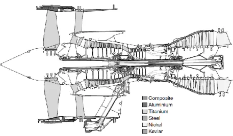
The superalloys are mainly used in the high temperature applications, including components for aircraft[20]. Fig.2.8. shows the materials for the aircraft engine, the huge used of this alloy are in (a)gas turbines; like disks, combustion chambers, bolts, casings and blades, (b) space vehicles and rocket engine parts, (c) Nuclear applications[22].
Figure 2.8: Cross section of the Rolls-Royce jet engine (extensive use of
nickel-based superalloys in the combustor and turbine sections)[1].
2.7. Physical metallurgy of nickel and its alloys
Nickel is one of the most widely used elements on earth and has a Face Centered Cubic (FCC) crystal structure as shown in Fig. 2.9[16]; it belongs, to the family of transition metals and exists in the form of five stable- isotopes. The elements that are alloyed with Ni to form superalloys and the phases they contribute to also is mentioned in the Fig. 2.10[16]. The melting temperature is 1455 °C and has a density of 8907 kg/m3 at room temperature. The low diffusion rate in FCC metals give good microstructural stability even at very high temperatures [1].
Figure 2.9: Face Centered Cubic (FCC) crystal structure[16].
Figure 2.10: Representation of different alloying elements present in Ni
Ni based superalloys belong to the family of austenitic nickel chromium based materials that typically contains 80% Ni and 20% Cr. Several alloying elements are included in different percentages depending on the need to achieve better mechanical properties. Ni based alloys are usually strengthened by precipitation (age) hardeners, they may be wrought or cast depending on the application and composition involved [17].The microstructure consists of different phases. The important ones such as gamma phase (γ), gamma prime (γ'), gamma double prime (γ''), delta phase (δ) and various carbides and borides are explained below [1]. The gamma phase (γ): The gamma phase is the matrix phase of nickel-based superalloys in which the other phases reside[1][16].
It exhibits an FCC crystal structure and its composition mainly consist of Ni with other elements such as Co, Cr, Mo, Ru, Re, & Fe[1][16].
Gamma prime (γ′): forms the precipitate phase, which is usually coherent with the γ-matrix and is the main strengthening precipitate in nickel-based superalloys. Similar to the γ phase γ′ have an ordered FCC crystal structure. γ′ mainly consist of Ni, Al, Ti, and Ta i-e Ni3(Al,Ti)[1][16].
Gamma double prime (γ′′): is a strong coherent metastable precipitate with a body center tetragonal (BCT) structure, it is the primary strengthening precipitate[1][16].
The γ′′ unit cell precipitate i-e Ni3Nb consist of Ni and Nb is shown in Fig.2.11[16], is usually found in Ni-Fe superalloys. At higher temperature γ′′ become unstable and can transform into δ phase[1][16].
Figure 2.11: The unit cell of γ′′ precipitate[16] .
Delta phase (δ): is a non-hardening precipitate usually present at grain
boundaries. The loss of hardening is due to depletion of γ′′. The structure is orthorhombic and the δ phase improves the creep rupture and grain
boundary sliding resistance. It is composed mainly of Ni, Nb and Ti. Carbides and borides: Carbide usually forms when carbon reacts with Ti, Ta and Hf and result in MC carbides, where M represents elements such as Cr, Mo, Ti, Ta, or Hf. The MC carbides break down during service to other species, such as M23C6, M6C, M7C3, and M3B2. These decomposed compounds usually reside in the γ grain boundaries. Borides are found in superalloy in the form of M3B2, having a tetragonal unit cell. Which is also present in grain boundaries and improve the creep rupture resistance of superalloys[1][16].
2.8. Inconel 718: Features and characterization
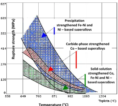
Inconel 718 alloy is an age-hardenable Ni-Cr-Fe based wrought superalloy, it is extensively used in the aerospace industry due to its high corrosion and oxidation resistance, high strength and long creep life at elevated temperatures [23]. Inconel 718 has a good machinability and welding capability in comparison with other superalloys [1]. Fig 2.12 shows the comparison of creep strength for all three types of superalloys with different type of strengthening[1][16]. Nickel based alloys, have a relatively high yield (700–1200 MPa) and tensile (900–1600 MPa) strength at room temperature, the most remarkable property is that they maintain their mechanical properties within a wide range of temperatures, (up to 600–800 °C)[16][17]. The mechanical properties (Table 2.2) depend on the chemistry
and the microstructural features, such as grain size, γ'/γ” size and distribution, carbide and boride size and content, and grain boundary
morphology. The metastable phase may finally transform into the stable phase δ (Ni3Nb) at temperatures above 650 °C after long term thermal exposure[1].During the hot forming process, the high-temperature deformation behavior of metals or alloys is generally very complex[20]. It is well known that the hot deformation behavior is sensitive to the thermo-mechanical parameters, such as the deformation temperature (T), strain rate (έ) and strain (Ɛ)[24][25].Complex deformation mechanisms, such as the work hardening (WH), dynamic recovery (DRV) and dynamic recrystallization (DRX), often occur in the metals or alloys with low stacking fault energy during the hot deformation [20].
For the multi-pass hot forming process, the static and metadynamic recrystallization behavior also occurs. At the beginning of hot deformation, the obvious work hardening behavior can often be observed for the low stacking fault energy alloy. So, actually the high temperature deformation is a competitive process of the strain hardening and dynamic softening mechanisms. Therefore, developing the suitable constitutive relations to describe the complex strain hardening and dynamic softening behavior of metals or alloys are significant [20].
Alloy UTS (MPa)
at temperature
Y.S. (MPa) at
temperature Tensile elongation (%) at temperature
21 °C 540 °C 760 °C 21 °C 540 °C 760 °C 21 °C 540 °C 760 °C Ni based Astroloy 1415 1240 1160 1050 965 910 16 16 21 Inconel 587© 1187 1035 830 705 620 605 28 22 20 Inconel 600 660 560 260 285 220 180 45 41 70 Inconel 718 1435 1275 950 1185 1065 740 21 18 25 Nimonic 75 745 675 310 285 200 160 40 40 67 Nimonic942© 1405 1300 900 1060 970 860 37 26 42 René 95 1620 1550 1170 1310 1255 1100 15 12 15 Udimet 720 1570 … 1455 1195 … 1050 13 … 9 Fe‐Ni based A ‐286 1005 905 440 725 605 430 25 19 19 Alloy 901 1205 1030 725 895 780 635 14 14 19 Incoloy 801 © 785 660 325 385 310 290 30 28 55 Incoloy 909 1310 1160 615 1020 945 540 16 14 34 Co based Haynes 188 960 740 635 485 305 290 56 70 43 MP159 2025 … … 1620 … … 10 … …
Table 2.2: Mechanical properties depending on temperature for selected
Figure 2.12: Stress-rupture characteristics of wrought Ni-, Fe-Ni- and Co-
based superalloys depending on the strengthening mechanism[3].
2.9. Workability and hot deformation behavior of
IN718
The hot deformation behavior of IN718 is usually investigated by using hot compression and torsion tests.[26][27][28]. Several models have been proposed in the form of a hyperbolic-sine[29], an exponential and a power law for hot compression of IN718[30]. Experimental data obtained by J.M.
Zhang et al[31], who analyzed the shape of the flow stress curves vs. deformation parameters, to develop a mathematical model.
Temperature (°C) Solid‐solution strengthened Co, Fe‐Ni and Ni – based superalloys Carbide‐phase strengthened Co – based superalloys Precipitation
strengthened Fe‐Ni and Ni – based superalloys R u p tu re str e n gth ( M Pa)
Recently, M.Z. Hussain et al.[32] proposed a constitutive relationship for thermo-mechanical processing of IN718 through double multivariate
nonlinear regression. Considering hot deformation of IN718, it is worth noting that it is essential to develop comprehensive equations for a wide range of temperature (T) and strain rate (έ). The mechanical properties of the alloy generally depend on the microstructure which is controlled by hot
deformation parameters such as temperature, strain and strain rate. So, the Arrhenius-type equation and processing map could play important
roles in characterization of flow stress behavior, optimization of process parameters and microstructure control for metals and alloys during hot deformation. Tan et al.[20] studied the hot deformation behavior of fine grained Inconel 718 superalloy. The flow stress values predicted by the developed Arrhenius-type constitutive equation were in reasonable agreement with the experimental values, and optimum process parameters were determined based on the established processing maps. The hot working characteristics of Ni-Cr-Mo-based C276 superalloy based on the flow stress
curves and microstructure were investigated by Zhang et al[21]. Fig. 2.13[28] shows the true stress–true strain curves obtained from the
Gleeble tests.
Figure 2.13: The true stress–true strain curves of IN718 at various strain
rates: (a) ε̇=0.001 s−1, (b) ε̇=0.01 s−1, (c) ε̇=0.1 s−1, (d) ε̇=1 s−1 [28].
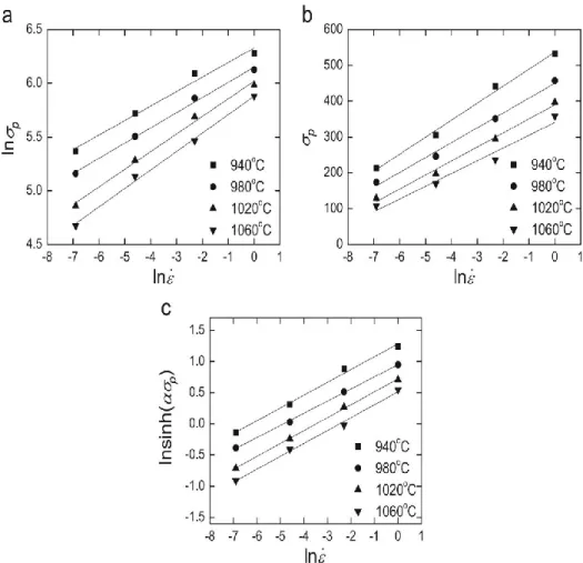
Fig. 2.14[28]. Shows the the relationship between ln σp and ln ε̇ and the
relationship between ln(sinh(ασp)) and ln ε̇ that are analysed within a value
of n1, β and n2 are 6.6, 0.0247 and 4.9, respectively. The value of the activation energy (Q) was 429.56 KJ/mol (Fig. 2.15) [28].
Figure 2.14: The dependence of the peak stress on strain rate at different
temperatures: (a) ln σp versus ln ε̇, (b) σp versus ln ε̇ (c) ln(sinh(ασp)) versus
Figure 2.15: ln(sinh(ασp)) versus 1/T [28].
2.10. Titanium Alloys
Titanium alloys are widely used in aerospace, primarily due to excellent strength to weight ratio and good high temperature properties. The high strength, coupled with low density (60% of that of steel) offer attractive weight saving[4]. For example, the landing gear of the Boeing 777 and the Airbus A380 achieved weight savings of over 580 kg by substituting certain struts, rods and beams of steel (4340M) for the titanium alloy Ti-10V-2Fe-3Al. Due to its corrosion and temperature resistance, titanium can be widely used in Jet engine component, airframes casing [33][34].
It’s very interesting also to note that using titanium in landing gear; can reduce the maintenance costs. Specific Titanium alloys have been designed to operate at over 600°C. Other advantages of titanium alloys for aerospace applications include their compatibility with carbon fiber reinforced polymer (CFRP); low modulus of elasticity and high ballistic resistance. Fig. 2.16. shows the typical titanium alloy usage in the aero-engine[35].
Titanium alloys find interesting applications also in chemical industry (e.g. reaction vessels) due to their corrosion resistance, and also in heat
exchangers. Beside of the chemical and aerospace applications, titanium alloys can be used also in other sectors, like marine and offshore applications. The sports car industry uses titanium alloys for coil springs and engine valves because of its high strength to weight ratio. Furthermore, Titanium alloys also find their use in medical applications such as hip and dental implants due to its biocompatibility [4].
2.10.1. Classification of titanium alloys
Titanium has a two elemental crystal structures, hexagonal close packed (hcp) at room temperature and body centered cubic (bcc) at higher temperatures (Fig.2.17)[4]. These two systems are the basis for the five classes of titanium alloys: α, near-α, α+β, near-β and β.The temperature at which the material transforms to 100% β is known as the β transus temperature (Tβ) [35].
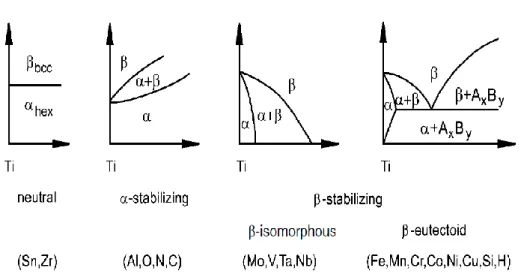
Properties such as plastic deformation and diffusion rate are closely connected with the respective crystal structure. Fig.2.18[4] classifies the alloying elements as neutral, α-stabilisers or β-stabilisers depending on their influence on Tβ[4].
Figure 2.18: Influence of alloying elements on phase diagrams of titanium
alloys[4].
The α phase field is extended to higher temperatures by α-stabilising
elements, while the β phase field is shifted to lower temperatures by
β - stabilising elements. Neutral elements have a negligible effect on Tβ.
Examples of α stabilisers include Al, O and N, and β stabilisers include Mo, Cr, Mn, V and Fe. [35]. Fig. 2.19 shows a schematic quasi-vertical section of a ternary titanium system containing both α and β stabilising solute species. The schematic shows the martensitic start and finish lines denoted-
as Ms/Mf which are close together. The classes of titanium alloy are marked at the top of the diagram [4].
Figure 2.19: Schematic quasi-vertical section for ternary titanium alloys
containing both α and β stabilising solute elements [4].
2.10.1.1. α alloys
Mainly consist in pure titanium (commercially pure Titanium), Ti-5Al-2.5Sn and Ti-0.3Mo-0.9Ni. This class of alloys is mostly α phase
Furthermore, contrary to α+β and β alloys, thermomechanical processing is
used to control the grain size rather than manipulate the microstructure. In addition to their high weldability, α alloys exhibit excellent corrosion
resistance. For this reason, commercially pure Titanium is the material of choice for manufacture of chemical and petrochemical processing equipment [4][36]. The weldability is useful in heat exchangers and other piping applications.
2.10.1.2. α+β alloys
Ti-6Al-4V (Ti-64) is the most popular titanium alloy in the aerospace industry. Today this type of (α+β) alloy accounts for more than 50% of all alloys in use and for near 90% of the titanium used in the aerospace market. Ti-64 can be heat treated up to tensile strengths of 1100 MPa via a solution treatment and aging process. These alloys have the best combination of processability, strength, ductility and durability [36][37].Ti-64 is weldable by almost all welding methods too. So, Ti-64, is used in almost every section of the aircraftincluding the fuselage, wing, empennage, nacelle and landing gear, usually in the annealed condition[4][38].
2.10.1.3. β alloys
β - alloys contain an extremely high concentration of β stabilizing elements
which results in the β phase being thermodynamically stable at room
temperature. An example of a β alloy is Ti-13V-11Cr-3Mo. β alloys give a high tensile and fatigue strengths along with easy fabrication into
sheet-type products. On the other hand, the disadvantages are low resistance to crack propagation and poor weldability[4][37].
2.11. Ti-6Al-4V features and characterization
Ti6Al4V is an + alloy, with 6 wt% aluminium stabilizing the phase and 4 wt% vanadium stabilizing the phase. At room temperature the microstructure at equilibrium consists mainly of the phase (hcp) with some retained phase (bcc) [39]. Ti6Al4V provides a good machinability and excellent mechanical properties, which offer the best performance for a variety of weight reduction applications in aerospace, automotive and marine equipment, racing and aerospace industry[38][40]. The Heat Treatment by hot Isostatic Pressing (HIP) is recommended for
fatigue-loaded components. The higher the solution heat treatment temperature, the smaller is the vanadium enrichment in the phase [41], leading to
transformation into hexagonal ’ upon quenching (from temperatures above 900C)[33]. Fig.2.20[4] is a schematic illustration of the microstructures resulting from quenching from various temperatures. The figure attempts only to illustrate the principle transformations upon quenching; in reality mixtures of both ’, ’’ and metastable/stable can occur, depending on chemical compositional variations[4].
Figure 2.20: A schematic illustration of microstructures occurring in
Ti-6Al-4V after quenching from different temperatures [4].
The − phase contains lower concentration of those elements (especially oxygen) that promote age hardening by formation of coherent Ti3Al
particles[4]. The mechanical properties of Ti-6Al-4V are also affected by the texture of the alpha phase[38]. Forming processes are usually
performed by hot rolling or hot forging in the phase field or in the + phase field which generally induces relatively sharp textures in the phase formed upon cooling[39]. Different investigations have been carried out to study the influence of the deformation parameters on microstructures and texture[36].
In the hot rolled of Ti-6Al-4V products, N. Gey et. al. found that the degree of deformation in the field (high temperature) significantly affects the inherited resulting texture[39]. Albrecht et. al. made some well-defined comparisons between mechanical properties and texture for Ti-6Al-4V[42]. Their work shows that the orientation of the basal plane with respect to the loading direction is of primary importance.
2.12. Workability and hot deformation behavior of
Ti-6Al-4V
Also in the case of titanium alloys, the hot workability is studied by using hot compression or hot torsion tests[43][44]. With hot torsion it is possible to apply large deformations while keeping the sample length constant[44]. Hot compression tests are suitable for determining material behavior at low strains[45]. The hot behavior of the Ti6AL4V was already investigated by Reddy[46], who limited his study on low strain-rates and low strains obtained during hot compression. Steady-state flow stress was also modeled by mean of regression for strain-rate up to 10/s taking into account the initial grain size. Prasad et al. investigate the Mechanisms of deformation of Ti-6Al-4V in the β phase domain using a hot compression; also he used an Arrhenius type equation to model the steady
state flow stress; the prior β grain size was also modeled as a function of the Zener-Hollomon parameter using a power law[47]. Fig. 2.21[44]
shows the flow curves for the torsion results under different strain rate; the steady-state flow stress and the maximum stress increase by increasing
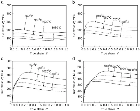
![Fig. 2.25 shows the relationships between some of the more commonly used alloys in the 7xxx series [5][48]](https://thumb-eu.123doks.com/thumbv2/123dokorg/2971421.27331/73.892.205.706.292.770/fig-shows-relationships-commonly-used-alloys-xxx-series.webp)