Table of contents
Executive summary List of acronyms Index
1. Introduction
2. Role of passive systems relevant for the mitigation of severe accidents 3. Passive safety systems for heat removal from the containment
4. Passive safety systems as specific measures for SAM 5. Passive system reliability
6. Performance assessment of Passive Containment Cooling System (AP600/1000-like configuration)
7. Performance assessment of Passive Containment Cooling System (ESBWR-like configuration)
8. Performance assessment of In Vessel Retention (IVR) systems by external cooling (safety injection)
9. Performance assessment of ECCS in LWR
10. Esemplification of a dynamic investigation of a PWR by means of DSA 10.1 ASME code: requirements for nuclear components
10.2 Reference NPP data 10.3 Dynamic transient analysis 10.4 Result discussion
11. Conclusions References
List of figures
Figure 1 – AP1000 Passive containment cooling system Figure 2 - Passive safety systems of the ESBWR
Figure 3 - A schematic picture of the passive containment cooling system for ESBWR Figure 4 - AP1000 IVR of molten core debris
Figure 5 - Flow chart of passive containment cooling system in AP1000 Figure 6 - Functional failure fault tree of PCCS system
Figure 7 - ESBWR-like PCCS schematic
Figure 8 - Schematic view of PCCS using horizontal heat exchangers
Figure 9 - External reactor vessel cooling system and cavity flooding system Figure 10 - Heat fluxes from the melting pool
Figure 11 – PWR ECCS configuration
Figure 12 – BWR ECCS configuration (Mark II containment) Figure 13 – Containment spray system design
Figure 14 – FEM model: Vertical section of the containment system
Figure 15 – Containment stress distribution due to the loads combination at time t=7.68 s Figure 16 – Horizontal displacement at hot leg and spray system restraints
List of tables
Table 1 – Characteristics of PWR spray headers
Table 2 – Characteristics of BWR spray headers (Mark III containment) Table 3 – Reference parameter for a 1000 MWe Westinghouse PWR Table 4 – Relevant data of RPV and SGs
List of Acronyms
AC Alternating Current
AP 600/1000 Advanced Passive
APR1400 Advanced Power Reactor 1400 MWe BWR Boiling Water Reactor
CCF Common Cause Failure CFS Cavity Flooding System CHF Critical Heat Flux
CSS Containment Spray System DBE Design Basis Earthquake
DC Direct Current
DDET Discrete Dynamic Event Tree DW Drywell
ECCS Emergency Core Cooling System
ENEA Italian National Agency for New Technologies, Energy and Sustainable Economic Development
ESBWR Economic Simplified Boiling Water Reactor
FV Filtered Venting
GDCS Gravity Driven Cooling System
GE General Electric
HEX Heat Exchanger
IAEA International Atomic Energy Agency ICS Isolation Condenser System
IE Initiating Event
IRWST In-Containment Refuelling Water Storage Tank
IVR In-Vessel Retention
LOCA Loss of Coolant Accidents LWR Light Water Reactor
MSIV Main Steam Isolation Valve
MSL Main Steam Line
MSLB Main Steam Line Break NPP Nuclear Power Plant
PAR Passive Autocatalytic Recombiner PCC Passive Cooling Condenser
PCCS Passive Containment Cooling System
PRA Probabilistic Risk Analysis, Probabilistic Risk Assessment PRHR Passive Residual Heat Removal
PSA Probabilistic Safety Assessment, Probabilistic Safety Analysis
PWR Pressurized Water Reactor
RCS Reactor Cooling System RPV Reactor Pressure Vessel
SA Severe Accident
SAM Severe Accident Management
SAMG Severe Accident Management Guideline SBWR Simplified Boiling Water Reactor
SBWR Simplified Boiling Water Reactor
SG Steam Generator
SSC Structure System and Components T-H Thermal-hydraulic WW Wetwell
Executive Summary
The implementation of the safety safeguards to reduce the risk due to severe accidents as one of the requirements arising from the lessons learned from the accident at Fukushima.
Such apparatuses include systems for the retention of the corium inside the vessel, accumulators, heat exchangers for evaporation, condensation systems as well as systems for ventilation through filters of containment for the abatement of pressure, etc.. They are designed for the prevention and mitigation of consequences of severe accidents.
In this context, the study focuses on passive systems, whose operation does not require any external input, upon which reliance is placed to exercise and ensure the safety functions such as removing heat from the containment and the control and abatement of the amount of hydrogen that could break free following a severe accident involving the melting of the core. However, considering the peculiarities of their operation, a careful analysis is required to ensure that these systems perform the required safety tasks.
In the context of the so-called "risk-informed decision making", which combines the deterministic and probabilistic aspects for safety assessment, the proposed activity consists of several stages:
• State of the art of passive systems usable for the "management" of severe accidents, to be considered for their implementation in the guidelines in emergency procedures.
• Analysis of safety on the probabilistic viewpoint, which aims to provide elements for the evaluation of performance, in availability/reliability terms.
• Deterministic analysis aimed to determine useful information on the residual strength capacity of NPP nuclear systems, operation capability and reliability, by properly taking into account the aging effects.
As for this latter, the investigation of the overall safety performance of nuclear components and systems, such as the containment system (ref.1), when they are facing severe accident conditions is of meaningful importance because it allows to predict the eventual failure of such components and/or their safety margin, to be intended like the residual strength against failure. Deterministic simulations, will provide useful information for the emergency preparedness, apart from that will allow, if possible, to upgrade the existing components (in agreement with outcomes highlighted in IAEA and WENRA documents investigating the Fukushima accident).
1. Introduction
The improvement of preventive and mitigative severe accident management measures, including hydrogen control and containment venting is a strong requirement coming from the Fukushima event and in consideration of the external hazards. Implementing the Severe Accident Management Guidelines (SAMGs), in addition to the Emergency Operating Procedures (EOPs), into the Probabilistic Safety Assessment (PSA) will indicate whether indeed risk is reduced by applying the various accident management strategies.
Severe Accident Management is defined as the cluster of actions that operators take when a severe accident has occurred:1) prevent reactor pressure vessel damage; 2) prevent reactor containment damage; 3) reduce radioactive substances leaked to environments.
Accordingly SAMG is a representative guidebook on the relative strategies: it specifies phenomena that develop after a severe accident and the actions taken by operators to mitigate the effects.
Severe accident management guidelines improvement imply the strengthening of emergency planning and preparedness, to withstand the impact of external hazards which can cause damage to the infrastructures and communication means, loss of equipment, stress and injuries on the personnel involved.
On the other hand the implementation of the guidelines concerning specific external events, or groups of external events with similar plant effect, in terms of suitable accident management measures and actions for both prevention and mitigation of severe accidents consequences (as mobile equipment and resource and plant management from alternative control rooms and emergency centers, operator training) on account of the more severe conditions dictated by the external event, requires their appropriate modeling within the PSA framework and the relative methodology enhancement.
In order to enable effective responses to beyond-design-basis events, attention is needed to strengthening and better integrating emergency procedures, extensive damage mitigation guidelines, and severe accident management-emergency operating procedures, as for:
− Coping with the complete loss of AC and DC power for extended periods.
− Depressurizing reactor pressure vessels and venting containments when DC power and installed plant air supplies (i.e., compressed air and gas) are unavailable.
− Preventing and mitigating the effects of large hydrogen explosions on cooling systems and containment.
− Operators training to respond to such scenarios involving the complete loss of onsite power supply as well as instrumentation and reactor control and the operation impairment by the harsh environment (hydrogen explosions, radioactive contamination and high temperatures) worsened by the effects of the external event itself (as for instance debris and flooding).
− Measures to cope with miscommunications in order to avoid failure in instructions transmission: in fact implementation of SAMGs involves technical decision-making, so that reliable communications are necessary.
− Symptom based procedures providing operators with the flexibility to respond to a wide variety of possible scenarios.
The resort to readily deployable offsite assets, as portable equipments and diverse and flexible strategies, mostly in terms of alternative power or water sources and the extensive use of passive safety systems, designed to extend the coping period in the event of an adverse situations such as occurred at the Fukushima Daiichi plant are among the relevant strategies envisaged to meet the requirements to implement revised SAMGs.
The study focuses on passive systems, whose operation does not require any external input, upon which reliance is placed to exercise and ensure the safety functions such as removing heat from the containment and the control and abatement of the amount of hydrogen that could break free following a severe accident involving the melting of the core.
However, considering the peculiarities of their operation, a careful analysis is required to ensure that these systems perform the required safety tasks.
In the context of the so-called "risk-informed decision making", which combines the deterministic and probabilistic aspects for safety assessment, the proposed activity consists of several stages:
• review of passive systems concepts usable for the "management" of severe accidents, to be considered for their implementation in the guidelines in emergency procedures,
• Analysis of safety on the probabilistic viewpoint, which aims to provide elements for the evaluation of performance, in availability/reliability terms.
• Deterministic analysis aimed to gain knowledge on the design of the system, its operation and reliability. The purpose is to evaluate the performance, critical features of these systems and as the latter may affect the containment resistance, for example, to cope with accidental critical situations. In this context it will consider the main factors that may affect the evolution of the accident scenarios and therefore the strategies of emergency planning.
Finally it’s important mentioning certain aspects non-specific of passive systems, such as the human factor and the integration of the human responses under severe accident conditions, that in some way interact under the development of strategies to cope with severe accidents.
2. Role of passive systems relevant for the mitigation of severe accidents
Following the path outlined in the previous section, the role of passive systems to cope with severe accidents has been recognized as a relevant aspect to be addressed within the Level 2 PSA (i.e. related to the radioactive releases frequency assessment) implementation in the light of Fukushima accident, as highlighted in ref.1.
Passive systems relevant to severe accidents and Level 2 PSA refer to different stages of the accident progress, i.e. the systems required to prevent the containment modes of failure due to overheating, the ones tasked to cool the debris bed after the core melt and measures to cope with the risk of hydrogen explosion.
Thus the screening process used to categorize passive systems into groups is the requirement that each one included should meet a functional requirement for reactor safety, thus allowing identify existing or proposed options for accomplishing LWR safety-related functional requirements, in this case heat removal from the containment and fission product confinement.
In NPP, the former is generally accomplished by means of passive spray system (steam condensation) and safety core cooling systems (operating at high, intermediate and low pressure), the latter is matched by guarantiing the containment integrity, even when it is
pressurised, and the cointament confinement through the main steam isolation valve (fail to safe system).
Given this context, the first category concerns the passive safety systems relevant to containment integrity and devoted to heat removal from the Containment, like e.g., Passive Containment Cooling System (PCCS) for AP1000 and PCCS condensers for ESBWR.
The other items refer more consistently to measures for Severe Accident Management strategy (SAM), e.g., passive autocatalytic recombiners to cope with hydrogen explosion risk and in-vessel retention of molten core via water cooling.
The primary function of this system is to retain and cool the molten core debris and keep the debris in a long-term coolable geometry to prevent damage to the integrity of the reactor containment structures. Interaction of molten or hot solid core debris with the concrete containment structure may generate explosive gases, overpressurize the containment structure, result in accelerated aerosol production, enhance heat transport to containment structure, and could ultimately breach the primary containment and release radioactive debris to the environment.
The identified systems are consistent with the available knowledge as emerging, for the most, from the literature exploration: relevant reports to refer to for system description include for instance IAEA TEC DOC-1474, Natural circulation in water cooled nuclear power plants
Phenomena, models, and methodology for system reliability assessments, November 2005,
and IAEA TECDOC-1624, Passive safety systems and natural circulation in water cooled
nuclear power plants, November 2009, respectively references 2 and 3.
Various concepts among the most relevant are here recalled and briefly described, for the groups identified above, according to the classification based on the functional requirements. Descriptions are not intended to provide detailed information, but rather, to describe the principles of operation, current status of development, and references where detailed information can be obtained.
3. Passive safety systems for heat removal from the containment
There are several conceptual candidate passive containment cooling systems which have been proposed and studied to date for either steel or dry double-wall concrete containment configuration of interest.
For example, passive containment cooling by thermal conduction, natural circulation and air convection has been proposed for AP600 and AP1000 reactors containment (PCCS, Passive Containment Cooling System).
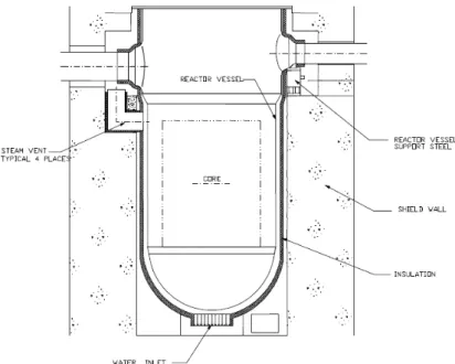
The steel containment vessel provides the heat transfer surface that removes heat from inside the containment and rejects it to the atmosphere (Figure 1). Heat is removed from the containment vessel by continuous natural circulation flow of air. During an accident, the air cooling is supplemented by evaporation of water. The water drains by gravity from a tank located on top of the containment shield building. The condensate inside containment is directed back into the In-containment Refuelling Water Storage Tank (IRWST) and the containment sump where it becomes a source of cool water in the sump recirculation process.
Figure 1 AP1000 Passive containment cooling system
Passive containment cooling system (PCCS), as a passive engineered safety feature first utilized in simplified boiling water reactors (SBWR) by General Electric (GE), is to provide steam suppression in the drywell in the event of Loss Of Coolant Accident (LOCA).
The Economic Simplified Boiling Water Reactor (ESBWR), GE’s latest evolution of BWR technology, utilizes PCCS, which is implemented in six independent loops, each containing a Heat Exchanger (HEX), as represented in Figure 2.
Figure 2 Passive safety systems of the ESBWR
Figure 3 A schematic picture of the passive containment cooling system for ESBWR The PCCS operates by natural circulation and its operation is initiated by the difference in pressure between the drywell and the wetwell. The PCCS condenser receives a steam-gas mixture supply directly from the drywell. In HEXs the gases are cooled and some or all of the steam vapour is condensed. The condensed steam is drained to the gravity driven cooling system (GDCS) pool and the non condensable gases are vented through the vent line, which is submerged in the pressure suppression pool. The vent line functions whenever the drywell-wetwell pressure differential is sufficient to clear the water from the vent line terminus within the pressure suppression pool. A more detailed schematic picture of the PCCS is shown in Figure 3.
4. Passive safety systems as specific measures for SAM
Passive systems relevant to Level 2 PSA refer to different stages of the accident progress, that is the systems tasked to cool the debris bed after the core melt and the ones required to prevent the containment modes of failure due, e.g., to overheating and assure containment structure integrity.
The first type refers to the late phase of the progression of a severe accident, associated with corium-melt discharge from the Reactor Pressure Vessel (RPV) and its relocation on the
concrete base mat in the form of a debris bed consisting of liquid/particulate corium. The core debris generates decay heat and attacks the concrete base mat and the containment structures and continues to do so, until the coolability of debris bed is achieved, as, for instance, with bottom coolant injection which occurs passively.
In-Vessel Retention (IVR) of molten core debris via water cooling of the external surface of the reactor vessel is an inherent severe accident management feature of the AP1000 passive plant. During postulated severe accidents, the accident management strategy to flood the reactor cavity with the IRWST water and submerge the reactor vessel is adopted to prevent vessel failure. The water cools the external surface of the vessel and prevents molten debris in the lower head from failing the vessel wall and relocating into the containment. Retaining the debris in the reactor vessel protects the containment integrity by preventing ex-vessel severe accident phenomena, such as ex-vessel steam explosion and core-concrete interaction, which consequent hydrogen and carbon oxide production.
The reactor vessel insulation design concept provides an engineered pathway for water-cooling the vessel as well for venting steam from the reactor cavity into the upper part of the containment, where eventually it is condensed.
Figure 4 provides a schematic of the AP1000 reactor vessel, vessel cavity, vessel insulation and vents configuration that promotes IVR of molten core debris.
With respect to the risk of explosion of hydrogen, as a result of metal-water reaction during a postulated core overheat (that is, Zircaloy-steam interaction) or molten core concrete interaction, the expected hydrogen hazard could be lowered through the implementation of passive preventive systems by providing the design with equipments inside containment to protect the plant and that automatically turn hydrogen gas into harmless water in the unlikely event of damage to the nuclear fuel. These safety devices, referred to as hydrogen passive (i.e., self-actuating or “autocatalytic”) “recombiners”, spontaneously recombine hydrogen and oxygen molecules, yielding steam and heat, which do not require neither operator action nor power supply or control. Hydrogen recombiners, denoted as passive autocatalytic recombiners (PAR), are intended to maintain the hydrogen concentration in the containment below levels that can support a hydrogen explosion, that is keep the hydrogen concentration below the explosive limit (i.e., at about 4 % by volume and above).
Ultimately it is important to mention the filtered vented (FV) containment as a standby system connected to a nuclear power plant containment structure, to maintain the containment boundary integrity.
Its function is to provide pressure relief for the reactor containment in order to avoid containment rupture following a postulated reactor accident, while limiting radioactive release to the atmosphere.
Thus it offers the advantages of both prevention of containment rupture because of over pressurization following a postulated reactor accident and control of radioactive release to the atmosphere following a postulated reactor accident.
It has to be underlined that these last two devices are not further treated in the present study, since the proven technology, the qualification with the specific environmental and accidental conditions of the NPP and the passive operation, give credit for a high reliability and excellent effectiveness.
These design features improve the containment performance to cope with severe accidents: in particular containment filtered venting system reduces the probability of late containment failure while passive autocatalytic recombiners reduces the probability of combustion-related phenomena inside the containment liable to rapidly lead to its loss, denoted as γ mode according to severe accident terminology.
In any case the combined effects of PARs and FV lead to a small risk reduction during the early release stage as regards the PAR effectiveness, because the early release is dominated by
containment isolation failures and containment bypass; on the other hand a significant risk reduction can be obtained by FV during the late release stage and any risk reduction from PARs in this respect is lower.
5. Passive system reliability
Performance of passive safety systems pertinent to severe accident, with main focus on the ones devoted to heat removal will represent a new challenge owing to the amount of uncertainties, as e.g. the condensation and boiling heat transfer coefficients or the heat transfer coefficients under the presence of non-condensable gases. Consequently difficulties arise to achieve a qualified reliability figure, since the scarcity of data and the little experience.
Due to the specificities of passive systems that utilize natural circulation (small driving force, large uncertainties in their performance, lack of data…), there is a strong need for the development and demonstration of consistent methodologies and approaches for evaluating their reliability. This is a crucial issue to be resolved for their extensive use in future nuclear power plants.
A passive system reliability assessment can be performed via application of various methodologies, as well documented in ref. 4 and 5. The individual techniques each maintain their own benefits and weaknesses: a margins-based approach often includes unnecessary conservatism, but has an accepted level of maturity since it has been utilized in licensing of AP600; a mechanistic approach resembling conventional risk analysis methods, which utilizes decomposition techniques and best-estimate parameters, enables clear identification and correlation of risk-dominant uncertainties and parameters, but the static event trees are often not suitable for capturing actual passive system behavior; a simulations-based approach, and specifically discrete dynamic event trees (DDETs), is more effective at capturing unexpected system behavior, despite the technique and associated technology is still somewhat immature relative to alternative techniques.
In PSA, the status of individual systems such as a passive system is assessed by an accident sequence analysis to identify the integrated behavior of a nuclear system and to assign its integrated system status, i.e. the end states of accident sequences. Because of the features specific of a passive system, it is difficult to define the status of a passive system in the
accident sequence analysis. In other words, the status of a passive system does not become a robust form such as success or failure, since “intermediate” modes of operation of the system or equivalently the degraded performance of the system (up to the failure point) is possible. This gives credit for a passive system that “partially works” and has failed for its intended function but provides some operation: this operation could be sufficient to prolong the window for opportunity to recover a failed system, for instance through redundancy configuration, and ultimately prevent or arrest core degradation. This means that the status of a passive system can be divided into several states, and each status is affected by the integrated behavior of the reactor, because its individual performance is closely related with the accident evolution and whole plant behavior.
This is even more relevant as far as thermal hydraulic natural circulation passive systems are concerned since their operation is strongly dependent, more than other safety systems, upon time and the state/parameter evolution of the system during the accident progression.
Merging probabilistic models with t-h models, i.e. dynamic reliability, is required to accomplish the evaluation process of t-h passive systems in a consistent manner: this is particularly relevant with regard to the introduction of a passive system in an accident sequence, since the required mission could be longer than 24 h as usual level 1 PSA mission time. In fact for design basis accidents, the passive systems are required to establish and maintain core cooling and containment integrity, with no operator intervention or requirement for a.c. power for 72 h, as a grace time.
The goal of dynamic PRA is to account for the interaction of the process dynamics and the stochastic nature/behavior of the system at various stages: it associates the state/parameter evaluation capability of the thermal hydraulic analysis to the dynamic event tree generation capability approach. The methodology should estimate the physical variation of all technical parameters and the frequency of the accident sequences when the dynamic effects are considered. If the component failure probabilities (e.g. valve per-demand probability) are known, then these probabilities can be combined with the probability distributions of estimated parameters in order to predict the probabilistic evolution of each scenario outcome. Given all this, the analysis shows the suitability of the dynamic approach for the integration of passive systems within the PSA framework.
Furthermore the inclusion of the external events in the analysis poses some additional challenges, as the components robustness assessment vs the external events: this should
include the conditional component (such as the items used to mitigate the severe accident consequences as to remove heat from the containment and keep containment pressure and temperature within approved limits) failure probabilities, upon both a single or a combination of external hazards, the fragility assessment of the safety components, that is the failure probability at each level of the hazard, such as the seismic fragility of the containment.
Depending on the involved systems response to the strength and duration of an external event, a set of different plant damage levels may need to be defined and analyzed.
In this context, probabilistic analysis should be used not only for ascertaining risk levels, but also for emergency and risk management measures definition, and in particular for SAMGs. In the next sections the foregoing systems are examined to evaluate their response to the threats posed by severe accident, as to maintain containment boundary integrity, to ascertain the fulfillment of their performance with respect to the safety requirements necessary to protect the health and safety of general public from radiological hazards.
6. Performance assessment of Passive Containment Cooling System (AP600/1000-like configuration)
All containments loose heat by heat conduction from inside of the containment to the atmosphere. A high heat conduction reactor containment cooling system can provide an ultimate heat sink to remove heat from containment after a postulated reactor accident.
This helps assure containment integrity by lowering containment temperatures and by reducing containment pressure. Containment pressure reduction occurs by both cool down of steam and cooling of non condensable gases.
The flow chart of the system illustrated in Figure 1 is shown in Figure 5. Air inlet vents near the top of the shield building direct air around the baffles and over the metal containment to transfer the heat from the reactor containment to the environment as shown in Figure 5. The system is designed to operate by natural convective flow of the air. Early in an accident, the heat load on the containment will be high. This heat load decreases with time. Short term containment cooling can be increased with a water storage tank placed over the reactor containment vessel at the top of the shield building with a gravity feed system that directs cooling water over the steel containment structure.
The water spray provides additional steel containment shell cooling by evaporation of water on the steel containment shell lowering its temperature early in a postulated accident when heat loads are particularly high. As the reactor decay heat decreases, the water flow is reduced using a passive device in the water storage tank that takes advantage of the water level drop in the tank.
Figure 5 Flow chart of passive containment cooling system in AP1000
Actually the passive containment cooling systems introduced in AP600/AP1000 design are based upon heat exchange process of steam condensation/evaporation between the steel containment and the heat sink (i.e., atmosphere) and include natural circulation, air convection, thermal conduction.
To date in the open literature there are not studies focusing specifically on the reliability of the system, rather the available studies investigate their efficiency/performance, that is the heat removal capacity of PCCS of advanced passive PWR during severe accidents. In ref.6, for instance, some severe accident sequences that present a containment high-pressure challenge are selected as representative accidents based on the PRA result and are used to estimate the containment response under the actuation of PCCS, to mitigate the consequences after the release of mass and energy during such scenarios as loss of coolant accident (LOCA) or main steam line break (MSLB). The results show that the heat removal capacity of PCCS during severe accident scenarios can keep the containment pressure below the acceptance criterion of for a range of severe accident challenges. PCCS water is delivered onto the containment at the high pressure signal caused by mass and energy released from RCS, and the water fills the PCCS distribution bucket at the top of the containment and establishes water film on the containment shell under gravity. Then, decay heat is transferred to steam inside the containment, and the steam condenses on the inner surface of the containment shell. PCCS then removes heat from the steel containment shell through outside water film cooling and air natural convection inside the air cooling flow channel between the containment shell and the concrete shield building.
Analysis in ref.7 shows that during severe accidents the AP1000 containment is likely to remain intact and to not be bypassed: as a result, the plant has a significantly reduced frequency of release of large amounts of radioactivity following core damage in an accident. The PCCS cooling capability is very reliable with the tank linked to the vessel by three redundant (and diverse) water drain valves. In addition, even with failure of water drain, air-only cooling is capable of maintaining the containment below the predicted failure pressure. The probability of system failure due to equipment fault is 1.7E-5, as indicated in ref.8.
The removal of heat is seen as successful when it avoids the containment pressure after 1000 seconds, Y, to exceed the safety limit of 0.4 MPa (ref.7). The Functional Failure Probability (FFP) is the probability of the containment pressure to exceed the safety limit.
For the passive system reliability analysis, the success criterion adopted is P containment < design
value: here, P containment is the total pressure in the containment, and design value is the critical
parameter if P containment exceeds such value it is considered that the containment will lose its
Some studies (ref.9,10) show, as atmosphere is the heat sink, the influence of the uncertainty in air temperature on the system failure modes and the sensitivity of the system operation and physical process failure probability to the heat sink temperature.
Since the reliability aspects are seen in terms of performance/efficiency rather than probability of system failure (that is the system operates or not), investigation on intermediate states for their evaluation within the safety analysis becomes essential, in accordance with the approach that credits the “partial” mode of operation of the system while assuring the safety function achievement, as described in the previous section.
This allows also overcoming a limitation in PSA framework, which is based on the binary representations of system states (i.e., success or failure), disregarding the intermediate states, which conversely concern the passive system operation.
In fact thermal-hydraulic passive systems are likely to be subject to challenging failure modes including performance degradation, as recognized in ref.11. Such systems may fail on relevant physical parameters (like flow rate and heat exchange) reduction to an unacceptable level due to degradation of the physical process itself: for example the flow rate may depend strongly on pressure losses in the natural circulation loop; as a result, minor alterations in the pressure drop due to corrosion or fouling, for instance, may sufficiently decrease coolant flow to an unacceptable level. Thus the system intermediate states are characterized by those values of the performance parameters falling within the range of the eligible ones. Clearly, in addition, the level of redundancy and diversification (like the three redundant and diverse drain valves) contribute to improve the rank of safety and reliability of the system.
The “functional” fault tree depicted in Figure 6 includes the likely failure modes impairing the PCCS system operation.
PCCS Failure
Figure 6 Functional failure fault tree of PCCS system
The results of a preliminary qualitative safety analysis don’t reveal relevant risk factors impairing the system performance such that the safety function is challenged. In addition the corresponding probabilities of the modes of failure are very low if not negligible. In fact both air circulation and internal condensation processes don’t need any external activation and it is quite unlikely that their operation can be compromised by t-h factors which may reduce the heat exchange process like surface oxidation and cracking or decrease the rate of natural circulation like the envelope failure and fouling. Finally water spray function is assumed to be guaranteed by the redundancy and diversification of the corresponding configuration, as mentioned earlier.
7. Performance assessment of Passive Containment Cooling System (ESBWR-like configuration)
Boiling in the core of a BWR occurs during normal power operation, plant transients, accidents and even after shut down due to the decay heat generation. The steam provided, if discharged to the containment, e.g. in LOCA or severe accident raises the containment pressure. The BWR employs suppression pools to condense the steam and keep the containment pressure below the containment design pressure level. The Passive Containment Cooling System (PCCS), as depicted in Figure 2, supplements the suppression pools and provides additional long-term condensation capability. The PCCs are connected to the
Air circulation flow
Internal
Drywell (DW) and to the Reactor Pressure Vessel (RPV) on two ends, so that any steam that leads itself into the Passive cooling Condenser (PCC) is condensed and the condensate is returned to the Gravity Driven Cooling System (GDCS) pool, so that the GDCS can continue to inject water into the RPV up to the depletion of the PCCS pool. The flow of water in the surrounding PCC pool water is accomplished by natural convection, and no forced circulation equipment is required. The steam produced in the PCC pools is vented to the atmosphere. There is sufficient water inventory above the top of the tube bundles to handle several days of decay heat removal, and eventually simple operator action allows continuing the passive heat removal for a long time.
In Figure 7 a schematic of the whole system is shown.
Figure 7 ESBWR-like PCCS schematic
It should be noted that condensation of high-temperature steam is an extremely efficient heat transfer mechanism, thus direct removal of core decay heat through condensers has always been an attractive option.
Results obtained from experimental and analytical investigations have pointed out that the presence of non-condensable gases, such as hydrogen and nitrogen, affects the efficiency of
PCC. These gases hinder the transport of steam to the condensing surfaces, reducing the condensation rate and consequently the efficiency of the condensers (ref. 12): for this reason non-condensable gases are vented through the vent line into the suppression pool in wetwell , as shown in Figure 8.
It has to be underlined that the gas distribution not only influences the PCC performance but also affects the containment pressure build-up, which is influenced by the volume of the non-condensable gas accumulated in the Wetwell (WW) gas space. The system pressure is hence substantially controlled by the transport of non-condensable gases from the DW to the WW and influences the PCCS performance. In fact natural circulation, in order to initiate its operation and achieve an “as expected” performance to accomplish heat transfer task, needs the required pressure differential between DW and WW.
Figure 8 Schematic view of PCCS using horizontal heat exchangers
Therefore the most important parameters affecting the PCCS performance are the drywell to wetwell differential pressure, the non-condensable gas mole fraction in the system, the pressure in the drywell, the number of PCCS units as well as the water pool level. The variability in PCCS performance based on physical parameters uncertainties leads to the possibility for system probabilistic estimation. This could be achieved by implementing the analysis by t-h simulations, through MELCOR code for instance, to provide understanding of the phenomena involved and help determine appropriate failure criteria: the drywell pressure
and temperature could be suitable candidates for failure criteria, as well as the energy transferred to the PCCS pool and/or the mass flow.
As in the previous section, the availability of research material addressing the system performance assessment on the probabilistic viewpoint, i.e., reliability, is quite limited. In accordance to ref.2 , PCCS is classified as a type B passive system, i.e. it relies on natural circulation. Its configuration and operation exhibits many analogies and similarities with the Isolation Condenser System (ICS) (ref. 13), utilised for decay heat removal function during an isolation transient. Therefore, given that a comprehensive reliability analysis is beyond the scope of the study, one proposes to refer to the similar reliability-oriented study performed for the ICS (ref.13) as a “referential”, although simplified investigative process, without going any further, while postponing a more meaningful PCCS reliability analysis to the next phase. We’ll limit to recall that, accordingly, the approach for the reliability assessment of such systems consists of two parts: the first part includes the classical reliability analysis of components and the second part concerns the passive function, in this case, natural circulation. System unavailability can be a result of either a defect of some component or a failure of natural circulation.
Natural circulation reliability is then evaluated through reliability analysis of the components designed to assure the best conditions for the function of it. It calls for identification of the mechanisms which maintain the intrinsic phenomena. Thus the reliability assessment can be conducted according to the classical procedure using for example fault trees (ref.13).
8. Performance assessment of In Vessel Retention (IVR) systems by external cooling (safety injection)
The cavity flooding strategy is adopted in managing accidents as the measure to achieve the SAM safety function referred to as in-vessel melt retention by external cooling. In this strategy, cooling water is injected into the reactor cavity to prevent reactor pressure caused by vessel failure.
The Korean Advanced Power Reactor APR1400 nuclear power plants adopt the cavity flooding strategy in managing accidents, ref.14. The cavity flooding system (CFS) consists of a refueling water storage tank in the reactor containment, an intermediate storage tank, a reactor cavity, a connecting line, valves, and related power sources.
When the cavity flooding system is operated, cooling water is passively injected into the reactor cavity. When the valve located on the intermediate storage tank connecting line is opened, the cavity flooding system is activated, and the refuelling water storage tank of cooling water in the reactor containment flows into the intermediate storage tank by gravity and the differential heads of the two structures. When the water level in the intermediate storage tank has reached the height of the reactor cavity connecting line, the cooling water flows into the reactor cavity by the same mechanism. The flooding stops when the water levels in the refuelling water storage tank and intermediate storage tank in the reactor containment and the reactor cavity are the same. If the cavity flooding strategy is successful, the temperature of the outer wall is maintained below the melting point of the reactor pressure vessel. Therefore, the cavity flooding strategy can prevent not only reactor pressure vessel failure but also radioactive substances from leaking to the outside by continuously supplying cooling water to the core meltdown products, even when it has failed to
maintain the soundness of the reactor pressure vessel.
That is, in the accident mitigation strategy, the cavity flooding system plays four roles: 1) minimizing and preventing the core meltdown products-concrete erosion; 2) minimizing and preventing the generation of hydrogen and carbon monoxide; 3) reducing the fission products released from core meltdown products-concrete reactions; and 4) cleaning the fission products released from captured core debris.
A sketch of the external reactor vessel cooling system and cavity flooding system is shown in Figure 9 below, with reference to the APR1400 configuration.
Figure 9 External reactor vessel cooling system and cavity flooding system
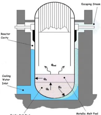
The necessary conditions of successful system performance and IVR strategy entail the reflooding of the reactor cavity (initial and longterm), the heat removal through the RPV wall with the associated t-h conditions in the cavity and the heat removal from containment. Heat fluxes from melt pool to be removed by the system to assure the coolability include, see Figure 10 below:
• Qd= from oxidic pool to vessel wall
• Qh= from oxidic pool to metallic layer
• Qrad= radiation losses from metallic pool surface
Figure 10 Heat fluxes from the melting pool
The most relevant modes of failure associated with RPV, whose occurrence is somewhat prevented by the external cooling system operation so as not to pose a hazard, concern (ref.15): the interaction of molten material with the RPV wall with the potential to lead to molten attack and erosion of the RPV steel; the molten material attack to fail the RPV penetrations; molten material stratification into oxidic and metallic debris leading to failure of the RPV; heat flux through the RPV shell above the Critical Heat Flux (CHF); long term corrosion leading to vessel failure and finally thermal and mechanical loads that the RPV is subjected to.
The probabilistic safety studies aim mostly at the assessment of the probability of RPV integrity challenge in terms of its capability to withstand the thermal loads, by comparing for instance the distributions of the wall heat flux and the CHF according to a defined safety criteria (as stating the estimated heat flux that must be removed from the lower head to ensure IVR of core melt exceed predicted heat fluxes and corresponding CHF), as reported in ref.16. However also in the present case the system pertinent availability and reliability aspects are for the most overlooked: at a first glance CFS failure includes the isolation valves faults (where in any case remote control to trigger the operation should be possible) and the gravity driven flooding mechanisms which entails the identification of the phenomena liable to hinder
the system operation, like line breakdown due to piping rupture or clogging (provided thermal insulation design that allows sufficient access of water to the bottom of the lower head [and not subject to clogging], and venting of a steam/water mixture on the top): from a preliminary qualitative evaluation the probability of failure of the system appears in any case as being not relevant.
For instance alongside an analysis basing on expert judgment the unreliability of the cavity flooding system, conditional on demand, is estimated at less than 1.0E-2. This includes, as a major contributor, human unreliability for system line and valves manually activation conservatively estimated at 1.0E-3 and CCF of valves.
It is plausible to believe that time window for operator response could be augmented so that the operator's unreliability should be below 1.0E-3 with adequate time and clear indications, including availability and survivability of instrumentation and display systems under severe accident conditions, that could prevent operators from taking action to flood the cavity.
We believe that with the importance attached to this accident management scheme, operator training, and comfortable time intervals available for action (hours), the actual unreliability would be low enough that, together with the very low frequency of any core melt sequence relevant to IVR, it renders an unflooded situation below a “screening” frequency levels of 1.0E-7 per year.
9. Performance assessment of ECCS in LWR
In PWR and BWR systems, the Emergency Core Cooling System ECCS will provide the safety function of the decay heat removal during a severe accident involving the double guillotine break of a cold leg (PWR) or recirculation line (BWR). In such an event, ECCS must assure that the design limits (acceptance criteria) are respected: the peak cladding temperature should never exceed 1204 °C, the amount of produced hydrogen must be lower that 1% of the maximum producible, the cladding oxidation thickness should be less than 17% of the total one, the core geometry must be coolable (i.e. avoiding balloning effect) and long term cooling must be guaranteed.
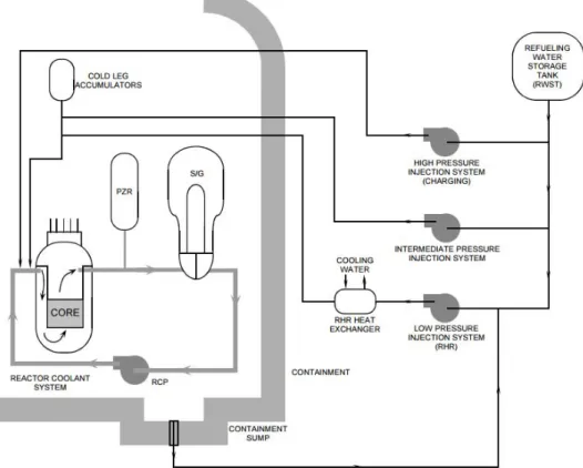
The ECCS is composed of several components and sub-systems with different operating pressure and flow rates to guarantee a high level of redundancy, diversification and multiplicity: ECCS configurations are shown in fig. 11 (PWR) and fig. 12 (BWR).
Figure 11 PWR ECCS configuration
The containment spray system is instead designed to perform several safety functions; among which the removal of the energy stored in steam and non condensable gases presented in the primary containment to limit the pressure peak intensity and to reduce the concentration of radioactive gaseous fission products that are released from damaged fuel assemblies during an accident (ref.17 and ref.18).
This system mainly consists of a containment spray storage tank (CSST), two containment spray system pumps, two heat exchangers and one or two lines of spray headers located at the top of the primary containment, fig. 13 (ref.17).
Sodium hydroxide is added to boron water for enhancing iodine removal. The system works in two conditions: the initial injection mode, in the first 30 minute of the accident sequence, during which the water is provided by the CSST and the heat load is higher, and the recirculation mode in which the water is directly taken by the collecting sump at the bottom of the primary containment. From that the need of no large damage into the containment structure.
The design of the system must assure that a large fraction of the containment volume is reached by the water droplets. The elevation of the spray headers is not the same between PWR and BWR, due to the different dimensions of the primary containments for these NPP (ref.19). More than 300 spray nozzles are presented on the headers; the design mass flow rate is 350 and 700 liters/sec for PWR and BWR, respectively.
The typical configuration of PWR consists of four concentric rings with radius and elevation listed in table 1. The same data for BWR are reported in table 2; the elevation is intended between the ground floor and the center of the header section.
Table 1 Characteristics of PWR spray headers
Header Radius [m] Elevation [m]
A B C D 2.48 7.72 12.87 18.13 40.5 39.0 37.3 36.0
Figure 13 Containment spray system design
Table 2 Characteristics of BWR spray headers (Mark III containment)
Header Radius [m] Elevation [m]
A B C 5.87 12.11 16.48 25.9 22.6 16.8
The typical Westinghouse PWR ECCS is composed of:
− 2 charging pumps injecting water through the 4 independent nozzles in the cold legs (pressure of about 170 atm);
− 2 IP injection pumps (pressure of 75 atm);
− 4 accumulators with volume of 38.2 m3 that passively inject water when the primary
− 2 LP injection pumps (pressure of 10 atm).
The main components of General Electric BWR ECCS are:
− HP Injection System, with an injection pump that is fed by a steam turbine (steam from MSL, no external power is required);
− Automatic Depressurization System (7 ADS Valves), which contributes to the depressurization of the primary loop to ensure the operation of LP systems in the case of high pressure scenarios;
− LP Core Spray System (2 CS Pumps); − LP Injection System (4 LPCI Pumps).
All the components use borated water taken from the refuelling or condensate water-storage tanks and coolant from the collecting sump once the supply tanks are empty.
In Generation III+ LWR, such as AP100 they are totally passive, while for EPR system they could be both passive and active (passive injection driven force and in some case with active power supply).
The single or multiple failure of these components may lead to non-removal of the heat of the core decay, corium-concrete interaction and finally, as previously mentioned, to the heating and pressurization of the containment wall.
Abrupt reduction of concrete strength will start soon the temperature exceeds 100°C: concrete hydration products contain chemically bound water that will be released when they are heated up to temperatures beyond 105°C. There are many phases in a heated cementitious material, some of which not fully reversible.
The primary effects on the containment will be the progressive structural damage, due to shearing and bending forces (combination of primary, secondary plus thermal and accidental loads) followed by cracking, spalling - ejection of target material because of pressurisation of concrete and failure.
10. Esemplification of a dynaic investigation of a PWR by means of DSA 10.1 ASME code: requirements for nuclear components
The design of nuclear components, systems and structures must be verified by considering the ASME Sect. III requirementsper each of the five classes in which they are classified:
− Class 1, for items of subsection NB: components that are part of the primary core cooling system or operated at elevated temperature.
− Class 2, for items of subsection NC: components important-to-safety emergency core cooling systems.
− Class 3, for items of subsection ND: components of the various systems necessary for plant operation.
− Class MC, metal containment vessels complying rules of Subsection NE.
− Class CS, core support structures constructed in accordance with Subsection NG rules.
Since design and testing conditions are out of the scope of this work, the attention is focused on the specific requirements, based on the maximum allowable stress intensity for the reference loading, that are given for each service condition; the defined conditions are: − Normal or level A, which refers to the planned operating state (prob. ~1);
− Upset or level B, the item must withstand the loadings without any damage requiring repair, this condition is expected to occur several times during the plant lifetime;
− Emergency or level C, in which large deformations are allowed, this situation is foreseen once in the power plant lifetime;
− Faulted or level D, these sets of limits permit gross general deformations with some consequent loss of dimensional stability and damage requiring repair, which may imply the removal of the component or support from service, the probability of such a condition is extremely low.
In the following sections, a deterministic assessment of a LWR containment system, comprehensive of the MSIV and spray system subjected to a design basis earthquake and LOCA conditions is performed in order to verify the reliability of the containment system itself in the case of faulted level.
10.2 Reference NPP data
The reference configuration of the plant is the 4 loops Westinghouse PWR (ref.17) with an electrical output of 1000 MW, Fig. 13. The heat produced within the core is removed by water at an average temperature of 300°C and pressure of 150 bar, which is sent to the four U-tube steam generators (SG) through the hot leg, and where it is cooled and sent back to the RPV by the primary pumps placed in the cold leg. Table 3 provides some useful reference parameters of this kind of NPP.
Table 3 Reference parameter for a 1000 MWe Westinghouse PWR
Parameters Reference value
Thermal power [MW] Electrical power [MW]
@ fuel assemblies Fuel array RPV ID [cm] Operating pressure [bar]
Temp. inlet [°C] Temp. outlet [°C]
@ SG
Steam pressure [bar]
3425 1150 193 17 x 17 439 150 291 325 4 69
The geometrical model, Figure 13, includes the primary containment and all the main components presented within the same: RPV, SGs, primary loop piping and reactor cavity. Volumes and masses of those components are consistent with the reference values (Table 4). The model of the containment takes into account both cement matrix and rebars (Figure 14).
Table 4 Relevant data of RPV and SGs Parameters Values RPV Φ (ID) [m] Thickness [m] Overall height [m] Overall mass1 [ton]
SG
ΦUpper (OD) [m]
ΦLower (OD) [m]
Thickness [m] Overall height [m] Overall mass2 [ton]
4.5 0.2 14 765 4.4 3.8 10 20.6 380
1 This value includes the masses of: vessel, core fuel and assemblies, lower internals, upper internals and coolant. 2 SG weight considers the internals and the inventory of coolant.
Figure 14 FEM model: Vertical section of the containment system
10.3. Dynamic transient analysis
To perform a dynamic transient analysis, the following strategy has been adopted: firstly the identification of the dynamic behaviour of the nuclear island during the reference DBE has been carried out with a numerical simulation, sect. 11, taking into account the main structures and components presented within the PWR primary containment, such as the RPV and the steam generators (SGs) and considering the MSIV as a puntual mass.
The results have been consequently used as input data for a detailed structural analysis of the MSIV or core cooling system, assuming that they are rigidly restrained to the containment wall.
The main aim of this analysis was to investigate the response of components, especially of the containment system, during a reference SA, consisting of a large break LOCA and a DBE that occur simultaneously.
The LOCA conditions have been implemented by means of proper boundary conditions applied to components and by considering the relative reduction of the material properties facing elevated temperature. Typical values of pressure and temperature reached during this transient are: p = 3.5 bar; T = 143 °C.
As for the earthquake, a PGA of 0.5 g, according to the new requirements to fulfill, has been used. The dynamic input was imposed by adopting the three corresponding accelerations time histories, calculated for a soil damping of 5%. The numerical simulations have been carried out with MARC© code.
10.4 Results discussion
The obtained results in terms of stress values (with the geometry and dimensions assumed) indicated/confirmed that the containment suffers local damages/failure phenomena: even if suffering void nucleation (cracking), the outer reinforced walls have/retain sufficient strength capability to withstand waves impact without jeopardize the overall plant integrity.
Figure 15 shows that the stress exceeds the allowable limit in mostly part of the containment wall (about 6 MPa as mean stress value). This may have as direct consequence an early failure of containment with possible loss of the containment isolation and confinement, even if the effects of the material degradation are limited by the action of the reinforcing steel bars. On that basis, the weakness of the plant examined appeared particularly in the bottom part of containment, at the bottom of the reactor cavity pit and along the SG compartment’s walls, at SGs and the hot leg restraints.
Pressurisation of containment (qualitative shape)
Figure 15 Containment stress distribution due to the loads combination at time t=7.68 sec.
The acceleration amplification along the height of the containment complies with what highlighted in ref.1. The containment building highlighted potential failure mode, with a maximum horizontal displacement of about 10 cm (in Figure 16 absolute displacement are shown). In addition, in Figure 16 the node 19408 refers to the hot leg-containment wall restraints; nodes 25337 and 25217 refer to the highest (H ~ 40.5 m above ground) and lowest (H ~ 36.0 m above the ground) spray system-containment wall restraints; finally the node 38297 refers to the SG- steam pipe jointing position.
Figure 16 Horizontal displacement at hot leg and spray system restraints
Due to the assumption assumed in representing the hot leg, deformation with plasticisation appear in the hot leg part close the SG outlet nozzle (Figure 15). It seems responsible for the
dissipation of seismic energy that is damped along the line and, so, did not overstress the MSIV. Finally, MSIV has been verified by adopting the ASME III Div. I – NB requirement and considering the level D condition in a triaxial stress state:
m b
l
m P P 4.8S
P + + <
where Pm, PL and Pb are the general membrane, local membrane and bending stresses and Sm
is the design stress intensity (for AISI F304 stainless stess at 350 °C is 110.3 MPa) that is a function of the material and the temperature. The corresponding criterion for the containment building, given by ASME sect. III, division 2 (Code for Concrete Containments) is instead:
where PC and SC are for primary and secondary compression stresses, while the subscripts M and B stand for membrane and bending; f’C is the compressive strenght of concrete (35 MPa).
By comparing the obtained values with the requirements it is possible to conclude that the integrity of the valves is guaranteed. Instead the verification of concrete is not satisfied because of heating effects on the internal walls due to synergie of the corium-concrete interaction and steam formation. Finally Figure 17 shows the deformed shape of the hot leg pipe. Nevertheless, since it has been represented in simplified 2D model, to investigate the real behaviour of such a pipe, for the transient postulated, it is necessary a proper dynamic analysis, which would take into account also the pipe whipping, the effect of jet impingement and the influence of the several restraints, distributed along the line.
11. Conclusions
Advanced reactor concepts imply substantial improvement of the containment functions with respect to the radioactivity confinement in case of a core melt accident. Such functions as containment heat removal, hydrogen management, core debris cooldown and prevention of basemat melt-through are probably among the most proper areas for passive systems usage. Many advanced water cooled reactors have implemented or considered different passive means to ensure these functions, whose concepts and most important features are firstly briefly recalled.
Safety considerations and preliminary reliability evaluations, also in order to evaluate and weigh up the relative effectiveness, are drawn basing on operational aspects and expected performance/availability of the systems apportioned to prevent and mitigate the consequences of severe core damage, albeit at the conceptual design level.
The available information here achieved support the conclusion that the implementation of reliable passive systems having an important role in severe accident management strategies is feasible and could be achieved for the plant designs.
Clearly the use of this conclusion for any specific application is subject to verifying the required reliability of systems, and to showing the appropriateness (by further testing as necessary) of the specific definite design.
Some ideas to enhance the assessment basis as well as performance in this respect, are also provided.
References
1. R. Lo Frano, L. Burgazzi, Application of risk-informed probabilistic and deterministic safety approach to estimate the risk of external events, ENEA report ADPFISS-LP1-050, September 2015
2. IAEA TEC DOC-1474, 2005. Natural Circulation in Water Cooled Nuclear power Plants. Phenomena, models, and methodology for system reliability assessments, November 2005
3. IAEA TECDOC-1624, 2009. Passive Safety Systems and Natural Circulation in Water Cooled Nuclear Power Plants, November 2009
4. L. Burgazzi, Addressing the challenges posed by advanced reactor passive safety system performance assessment, Nuclear Engineering and Design, Vol. 241, (2011),
1834–1841
5. D. Grabaskas and T. Sofu, “Review of Passive System Reliability Modeling Approaches for Advanced Small Modular Reactors,” Proceedings of ANS PSA 2013 International Topical Meeting on Probabilistic Safety Assessment and Analysis, Columbia, SC, Sept. 22-26, American Nuclear Society)
6. L. Tong , et al., Study on heat removal capacity of PCCS of advanced passive PWR during severe accidents, Nuclear Technology, Vol. 191, (July 2015), 15-26
7. T.L. Schultz , Westinghouse AP1000 Advanced Passive Plant, Nuclear Engineering
and Design, Vol. 236, (2006,) 1547–1557
8. J.L.Foret., “AP1000 Probabilistic Safety Assessment”, chapter 13, Pittsburgh, PA, Westinghouse Electric Company LLC (2003)
9. Yu Yu, et al., Correlation analysis for screening key parameters for passive system reliability analysis, Annals of Nuclear Energy, Vol. 77, (2015), 23–29
10. Yu yu et al. “Functional Failure Analysis for Passive Containment Cooling System in AP1000” Transactions of the American Nuclear Society, Vol. 108, (2013), Atlanta,
Georgia, June 16–20, 547-549
11. L. Burgazzi, Passive system reliability modeling of the combination of failure modes, Proceedings of the 24th International Conference on Nuclear Engineering,
12. T. Bandurski, M. Huggenberger, J. Dreier, C. Aubert, F. Putz, R.E. Gamble, G. Yadigaroglu, Influence of the Distribution of Noncondensables on Passive Containment Condenser Performance in PANDA, Nuclear Engineering and Design,
Vol. 204, (2001), 285-298
13. L. Burgazzi, “Passive System Reliability Analysis: a Study on the Isolation Condenser”, Nuclear Technology, Vol. 139,(2002), 3-9
14. Moosung Jae et al., “A New Methodology to Evaluate Severe Accident Management Strategies Using Decision Tree”, Transactions of the American Nuclear Society, Vol.
113, (2015), Washington, D.C., November 8–12, 795-797
15. D. Home and M. Chai, “Determination of In-Vessel Retention Under Molten Corium Pool Attack”, Proceedings of NURETH-16, Chicago, IL, August 30-September 4, 2015
16. J. Hong Park, “An assessment methodology for in-vessel corium retention by external reactor vessel cooling during severe accidents in PWRs”, proceedings of the Korean Nuclear Society Autumn Meeting, Taejon, Korea, October 2000
17. “The Westinghouse pressurized water reactor nuclear power plant” Westinghouse Electric Corporation, 1984
18. IAEA Safety Guide No. NS-G-1.10, “Design of Reactor Containment Systems for Nuclear Power Plants”, 2004
19. NUREG/CR-5966 “A Simplified Model of Aerosol Removal by Containment Sprays”, 1993
CIRTEN Authors CV
Rosa Lo Frano (Ph. D) is professor assistant at the Nuclear Engineering courses of Mech., Chem. and Nuclear Engineering Design, Design of Complex Plant and Nuclear Plants.
The research activity refers mainly the safety issues of nuclear installations, structural integrity, transport of radioactive materials, etc..
She is also one of the scientific referees for projects and contracts at national and international level, such as the AdP MSE-ENEA 2008-09, PAR 2010 and 2011, ELSY, LEADER, GENTLE2012; NUGENIA, IGD-TP, etc..
Donato Aquaro is full Professor of Nuclear Power Plants, at the Faculty of Engineering of University of Pisa. He teaches Structural Mechanics and Nuclear Construction in the undergraduate course in nuclear engineering. He is head of the department and head of the Master in Nuclear Safety and Security. Prof. Aquaro has been responsible of several research programs funded by Public and Private Institution(Ministry of University and Research, European Union, ENEL, ENEA, ANSALDO). Since 1987 until 1996, He has been member of Industrial Engineering Committee of the 'Consiglio Universitario Nazionale – MURST'.
He is reviewer of R & D programs presented by Companies at the Ministry of Economical Development. He evaluates the R & D programs funded by several Italian Regions (regioni Lombardia, Piemonte, Veneto, Emilia Romagna e Marche )
The Donato Aquaro research activities concern with the mechanical design, theoretical and experimental analysis of conventional and nuclear components from the thermal, fluid dynamic and structural point of view. In particular He has carried out researches on these subjects:
- analysis of nuclear components ( spent nuclear fuel cask) under impact loads
- methods of structural analysis of components made of monolithic ceramic and ceramic matrix composite - analysis of components operating at very high temperature - design of components for electric power generation; applications of renewable energy.
Professor Aquaro is member of the following scientific association: IASMiRT ( International Association on Structural Mechanics in Reactor Technology), UIT (Unione Italiana di Termofluidodinamica).