Ph.D. Course In Systems, Energy, Computer and Telecommunication Engineering
XXXI Cycle
Ph.D. Thesis
ENHANCING INTEROPERABILITY IN INDUSTRY 4.0
Marco Stefano Scroppo
Coordinator Prof. Ing. P. Arena Supervisor Prof. Ing. S. Cavalieri
...in everliving memory of my beloved grandmother M., recently passed away. I really miss you so much...
CONTENTS
1 Introduction 1
2 OPC UA - IEC 62541 7
2.1 OPC UA AddressSpace and Information Model . . . . 7
2.1.1 OPC UA NodeClass . . . 8
2.1.2 OPC UA Events . . . 11
2.1.3 OPC UA References . . . 12
2.1.4 OPC UA Graphical Notations . . . 14
2.1.5 OPC UA DataType . . . 15
2.1.6 OPC UA ModellingRules . . . 19
2.2 OPC UA Services . . . 21
2.2.1 OPC UA Discovery Service Set . . . 21
2.2.2 OPC UA Session Service Set . . . 21
2.2.3 OPC UA Browse, Read and Write Services . . . 21
2.2.4 OPC UA Subscription and MonitoredItem Ser-vice Sets . . . 22
2.4 OPC UA for Devices . . . 27 2.4.1 OPC UA Device Model . . . 28 2.4.1.1 TopologyElementType ObjectType . . 28 2.4.1.2 DeviceType ObjectType . . . 30 2.4.1.3 ConfigurableObjectType ObjectType . 30 3 JavaScript Object Notation (JSON) Data Interchange
Format 33
3.1 JSON base types . . . 33 3.1.1 JSON Example . . . 34 3.2 JSON Schema . . . 36
4 Open Connectivity Foundation (OCF) 41
4.1 OCF Resource Model . . . 41 5 Integration between OPC UA and the Web 49 5.1 OPC UA Web Platform Architecture . . . 50
5.1.1 Web User’s basic knowledge needed to access the OPC UA Web Platform . . . 53 5.1.2 Web User’s communication technologies needed
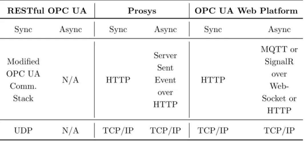
to access the OPC UA Web Platform . . . 61 5.2 Improvements of the proposal over the related work
present in literature . . . 62 5.2.1 OPC UA Web Platform versus RESTful OPC
UA solution . . . 64 5.2.2 OPC UA Web Platform versus Prosys solution . 65 5.2.3 OPC UA Web Platform versus OPC UA
Pub-Sub Specification . . . 69 5.3 RESTful Interface . . . 73
CONTENTS
5.3.1 Web User Authentication . . . 75
5.3.2 Information about Data Sets . . . 75
5.3.3 Information about Nodes . . . 76
5.3.3.1 Decoding Procedure of the OPC UA Variable Value . . . 79
5.3.3.2 Fulfilling GET request through OPC UA Services . . . 82
5.3.3.3 Case Study . . . 85
5.3.4 Updating value of Variable Nodes . . . 92
5.3.5 Monitoring Variable Nodes . . . 94
5.3.5.1 Case Study . . . 99
5.3.6 Stop Monitoring Variable Nodes . . . 101
5.4 OPC UA Web Platform Implementation . . . 101
6 Integration between OPC UA and OCF 103 6.1 Mapping from OPC UA Information Model to OCF Resource Model . . . 104
6.1.1 Mapping idea . . . 104
6.1.2 ”x.opc.device” Device Type . . . 111
6.1.3 ”x.opc.object” Resource Type . . . 112
6.1.4 ”x.opc.datavariable” Resource Type . . . 119
6.1.5 ”x.opc.method” Resource Type . . . 121
6.1.6 Mapping OPC UA DataType and OPC UA Variable Node Value attribute . . . 124
6.1.6.1 Built-in DataType . . . 126
6.1.6.2 Enumeration DataType . . . 126
6.1.6.3 Structured DataType . . . 127
6.1.7 Case Study . . . 131 6.2 Mapping from OCF Resource Model to OPC UA
Infor-mation Model . . . 139 6.2.1 Mapping idea . . . 139 6.2.2 OCFResourceType ObjectType . . . 146 6.2.3 OCFResourceInstanceType ObjectType . . . . 149 6.2.4 OCFDeviceType ObjectType . . . 150 6.2.5 CaseStudy . . . 157 6.3 Contribution of the proposal inside the OCF
standard-isation activity . . . 161
LIST OF FIGURES
2.1 OPC UA Graphical Notations . . . 14 2.2 Example of using a TypeDefinition inside a Node . . . 15 2.3 Example of OPC UA Structured DataType description 17 2.4 ModellingRule graphical notation adopted . . . 20 2.5 OPC UA Device Model . . . 28 2.6 OPC UA TopologyElementType ObjectType . . . 29 2.7 OPC UA ConfigurableObjectType ObjectType . . . . 31 4.1 OCF Device instance of ”x.my.device” Device Type . . 46 4.2 OCF Device made up by a subdevice . . . 47 5.1 OPC UA Web Platform Architecture . . . 50 5.2 Example of OPC UA AddressSpace . . . 58 5.3 Web User’s view of the OPC UA AddressSpace shown
by Figure 5.2 . . . 59 5.4 OPC UA PubSub Model . . . 70 5.5 Possible use of the OPC UA PubSub model inside the
5.6 Graph realised by cutting OPC UA AddressSpace . . . 77
5.7 Mapping the GET Request with OPC UA Services . . 82
5.8 Check Existence of OPC UA Client and Session . . . . 83
5.9 OPC UA AddressSpace used in the Case Study . . . . 85
5.10 TController DataType . . . 87
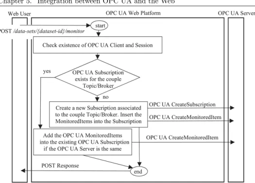
5.11 Realization of Monitor through OPC UA Services . . . 96
5.12 Publishing Procedure through the Topic/Broker . . . . 97
6.1 Example of the proposed mapping from OPC UA to OCF105 6.2 Mapping of OPC UA HasEventSource Reference . . . . 110
6.3 Example of Value of MyType DataType . . . 129
6.4 Subset of OPC UA AddressSpace to be mapped to OCF 133 6.5 Description of OrderType DataType . . . 133
6.6 OCF OPC UA Information Model . . . 140
6.7 Prohibition of multiple inheritance in OPC UA . . . . 142
6.8 Example of OCFResourceInstanceType and OCFRe-sourceType . . . 145
6.9 Light.BrightnessType ObjectType details . . . 147
6.10 OCFResourceInstanceType ObjectType . . . 149
6.11 OCFDeviceType ObjectType . . . 151
6.12 HasResource and HasSubdevice ReferenceTypes . . . . 152
6.13 SubdeviceInstanceType ObjectType . . . 154
6.14 ColType ObjectType . . . 155
6.15 Contains ReferenceType . . . 156
6.16 OCF Device belonging to the CustomDevice Device Type158 6.17 Mapping of the OCF Device of Figure 6.16 . . . 159
6.18 Mapping of the OCF Resource of Listing 6.3 . . . 160
LIST OF TABLES
2.1 Structure of each element of the array relevant to Value
attribute of EnumValues Property Node . . . 16
4.1 OCF Common Properties defined by ”oic.core” Re-source Type . . . 43
4.2 OCF Device Type Example . . . 45
5.1 Web technologies adopted in the proposal versus exist-ing solutions . . . 63
5.2 Basic Knowledge held by Web User versus existing so-lutions . . . 63
5.3 Resources and HTTP methods defined . . . 74
5.4 Attributes of Controller1 DataVariable . . . 86
6.1 ”x.opc.device” Device Type . . . 112
6.2 OCF Properties defined by ”x.opc.object” Resource Type113 6.3 JSON object of the OPCProperties array . . . 115
6.4 OCF Properties defined by ”x.opc.datavariable” Re-source Type . . . 119 6.5 OCF Properties defined by ”x.opc.method” Resource
Type . . . 122 6.6 Mapping OPC UA DataTypes and array into JSON
base types and OCF data types . . . 124 6.7 JSON object representing a single enumeration value . 126 6.8 JSON object representing a field of a Structured
DataType . . . 128 6.9 OCF Properties defined by ”oic.r.switch.binary”
Re-source Type . . . 144 6.10 OCF Properties defined by ”oic.r.light.brightness”
Re-source Type . . . 144 6.11 Mapping rules for OCF Resource addressed by ”/oic/d” 153 6.12 OCF CustomDevice Device Type . . . 157
LISTINGS
3.1 JSON Example . . . 35 3.2 JSON Schema Example validating the JSON Example
shown in Listing 3.1 . . . 38 5.1 JSON Schema for the description of the Node state . . 78 5.2 JSON Schema for ValueTypeSchema property in the
case of Built-in DataType . . . 80 5.3 JSON Schema for ValueTypeSchema property in the
case of Structured DataType . . . 81 5.4 JSON document received by the Web User for GET on
”/data-sets/1/nodes/2-79” . . . 88 5.5 JSON Schema for ValueTypeSchema property in the
case of TController Structured DataType . . . 90 5.6 The JSON document built using the current
Con-troller1 Value . . . 91 5.7 JSON document received by the Web User for GET
request on ”/data-sets/1/nodes/2-80” . . . 91 5.8 JSON Schema for Variable value and/or status
5.9 Example of JSON document created for the monitoring of the Node Controller1 (ns=2;i=80) . . . 100 6.1 JSON document representing the OPC UA
Orders-Folder Node . . . 132 6.2 JSON document representing the OPC UA Order1 Node136 6.3 OCF Resource representing a bulb . . . 143
CHAPTER
ONE
INTRODUCTION
Since few years, Industry has been featured by a revolution, the fourth one. The fourth industrial revolution has been coined with different names in different countries; the most known is Industry 4.0. It fea-tures the application of modern Information & Communication Tech-nology (ICT) concepts, such as Internet of Things (IoT) [1], in in-dustrial contexts to create more flexible and innovative products and services leading to new business models and added value [2, 3]. The emerging Industrial Internet of Things (IIoT) [4] is one of the main results of this revolution.
Realisation of this novel vision may be achieved only if a big ef-fort is really put to make interoperable the interchange of information between different industrial applications [5]. In order to provide for interoperability, definition and adoption of communication standards are of paramount importance [6]. For this reason, during the last few years, different organisations have developed reference architectures
to align standards in the context of the fourth industrial revolution. Among the various standards taken in consideration by these ref-erence architectures, OPC UA international standard (IEC 62541) [7, 8] seems to be one of the leading candidates to become a reference standard in this new era. As for example, the Reference Architec-ture Model for Industrie 4.0 (RAMI 4.0) [9], which defines a three-dimensional matrix that can be used to position existing standards in the fourth industrial revolution, indicates for OPC UA the role to standardise machine-to-machine communication. Another example is the Industrial Internet Reference Architecture (IIRA), which is a standards-based open architecture defined by the Industrial Internet Consortium (IIC) [10]. The objective of IIRA is to create a capabil-ity to manage interoperabilcapabil-ity, to map applicable technologies, and to guide technology and standards development. Also in this case, OPC UA plays a strategic role as it is one of the core connectivity standards inside IIRA.
Even though OPC UA already combines features coming both from industrial and ICT contexts, several activities have been carried on during these last years. These activities have the aim to introduce ICT enhancements into OPC UA in order to further improve its us-ability inside the fourth industrial revolution and, in particular, in the IIoT. As for example, literature presents some proposals to combine OPC UA and REpresentational State Transfer (REST) architecture style [11]; in particular, the usage of RESTful Web Services [12] to access OPC UA is widely described [13, 14, 15]. This is due to many advantages of RESTful Web Services in industrial settings as shown in [13, 16] and to its usage in the context of IoT architectures [17].
Chapter 1. Introduction
no universal language exists for the Internet of Things. In the IoT market, device makers have to choose between either using different frameworks (e.g., provided by Apple, Amazon, or Google), which limit their market share, or developing their own framework for standardis-ation across multiple IoT ecosystems, which increases their costs. This might also create a challenge for end users to ensure that the prod-ucts they use are compatible with the ecosystem they have acquired or alternately, to find some other ways to integrate their devices into the network. To overcome this, industry players have come together to form associations/foundations and consortiums of standards around the various IoT components, including connected buildings, connected home and industry IoT.
Open Connectivity Foundation (OCF) is one of the biggest trial connectivity standards organizations for IoT [18]. It is an indus-try group whose aim is to develop specification standards to ensure a set of secure interoperability guidelines for consumers, businesses, and industries by delivering a standard communication platform and providing a certification program for devices associated with the IoT. Very recently, OCF has defined a set of specifications which lever-age existing industry standards and technologies, provide connection mechanisms between devices and between devices and the cloud, and manage the flow of information among devices, regardless of their form factors, operating systems, service providers or transports. At this moment, OCF specification are under ISO/IEC standardisation under the project FDIS 30118 by ISO/IEC JTC1 Information Tech-nology committee.
As pointed out in this introduction, one of the main goal of Indus-try 4.0 is the interoperability of industrial applications and the use
of enabling ICT technologies such as IoT. Due to the presence of dif-ferent communication protocols in the current Industry 4.0 and IoT scenarios, interoperability may be achieved only through integration of these protocols. This integration must enable information exchange between the several industrial applications built on them. Integration of different protocols can be realised in several ways achieving various levels of interoperability according to the main features of the integra-tion itself [19]. As for example, interoperability between two different ecosystems can be achieved by mapping the data model structures of the ecosystems to be integrated.
Taking into account OPC UA, current literature present several ex-amples of interoperability between this standard and other protocols. Among them, [20] describes a solution for enabling interoperability between OPC UA and DPWS. Another example is the draft version of the mapping between OPC UA and DDS [21] (which is another core standard of IIRA [10]).
Given these premises and acknowledged the importance of OPC UA in this fourth industrial revolution, the research carried out dur-ing the Ph.D. course and described in this thesis was focused on the investigation about the enhancement of interoperability in Industry 4.0, IoT and IIoT. The research aim was to propose interoperability improvements based on OPC UA and, in particular, on the mapping of its information model in a different ecosystem.
First of all, the research was focused on the realisation of a proposal enabling the interoperability between OPC UA and generic users not compliant with OPC UA standard; in particular, it has been assumed to propose a way to allow the interaction between OPC UA and devices or applications using web technologies and without any knowledge of
Chapter 1. Introduction
the standard. The realization of this integration has been achieved through the definition of a novel data model mapping the OPC UA Information Model, based on common web data-formats (e.g. JSON). In the following, this proposal will be called Integration between OPC UA and the Web.
After that, the research focus has been enlarged to propose a so-lution enabling the interoperability between OPC UA and IoT/IIoT ecosystems. Among the current IoT/IIoT ecosystems, OCF has been chosen for the integration with OPC UA, as it seems a promising solu-tion to standardise the exchange of informasolu-tion into IoT as explained before. The solution mainly aims to realise a mapping between OPC UA and OCF information models, called in the following Integration between OPC UA and OCF. Through this mapping, information main-tained by an OPC UA Server may be used to populate a device compli-ant to OCF specifications which acts as a server, allowing it to expose this information to whatever client device in the OCF ecosystem. Vice versa, information maintained by an OCF Device may be published by an OPC UA Server allowing to make this information available to whatever OPC UA-compliant device.
The thesis is organized as follows. First of all, an overview about the fundamental elements used in this research is provided. In partic-ular, the OPC UA standard is described in Chapter 2, the JSON data format is analysed in Chapter 3 and the OCF ecosystem is described in Chapter 4. After these overviews, the results of the research will be provided: Chapter 5 describes the Integration between OPC UA and the Web and Chapter 6 describes the Integration between OPC UA and OCF.
CHAPTER
TWO
OPC UA - IEC 62541
The aim of this chapter is to deepen some features of the OPC UA international standard (IEC 62541) needed to understand the content of the thesis. OPC UA is mainly based on a Client/Server communi-cation model. Very recently, an extension of OPC UA called PubSub [22] has been released and defines a communication model based on Publish/Subscribe pattern [23] in addition to the Client/Server one.
2.1
OPC UA AddressSpace and
Informa-tion Model
Inside an OPC UA Server, OPC UA Nodes are used to represent any kind of information, including variable instances and types. The set of OPC UA Nodes inside an OPC UA Server is called AddressSpace [24].
Inside the OPC UA AddressSpace, OPC UA Nodes may be or-ganised into different subsets, called Information Models [25]; each of them is identified by a unique Namespace URI. An Array named NamespaceArray contains the URIs relevant to the Information Mod-els of an OPC UA AddressSpace; each URI in a NamespaceArray is accessed through an integer index, called NamespaceIndex. Informa-tion Model relevant to index 0 is mandatory and refers to the native OPC UA Information Model. Each Node inside an Information Model is univocally identified by an Identifier. A Node inside an OPC UA AddressSpace is identified by an attribute named NodeId, which is a couple composed by a NamespaceIndex (ns) and an Identifier (i).
2.1.1
OPC UA NodeClass
An OPC UA Node belongs to a NodeClass which defines the attribute of the OPC UA Node. Each NodeClass is derived from the Base Node-Class which defines the common attributes of OPC UA Nodes, among which: NodeId (which identifies the OPC UA Node inside the OPC UA AddressSpace), Description (which is a localised textual descrip-tion of the OPC UA Node) BrowseName (used to identify the OPC UA Node when browsing the OPC UA AddressSpace) and Display-Name (which contains the name of the OPC UA Node that should be displayed in a user interface). OPC UA defines the following Node-Classes:
• Variable NodeClass, used to model values of the system. Two types of Variable are defined: Property and DataVariable. A Property contains server-defined metadata characterising what other OPC UA Nodes represent. A DataVariable represents the
Chapter 2. OPC UA - IEC 62541
data of an OPC UA Object and it may be made up by a col-lection of other OPC UA DataVariable Nodes. The Variable NodeClass features the Value attribute containing its current value; another attributed called DataType contains the NodeId of a Node providing type definition for the Value attribute of the Variable Node.
• VariableType NodeClass, used to provide type definition for Vari-ables. OPC UA standard defines the BaseVariableType which all the VariableTypes must be extended from. OPC UA already defines several standard VariableTypes derived from BaseVari-ableType. Among them there are the BaseDataVariableType and the PropertyType. The former is used to define a DataVari-able Node, whilst the latter defines a Property Node.
• DataType NodeClass, used to provide type definition for the Value attribute of a Variable Node.
• Object NodeClass, used to represent real-world entities like sys-tem components, hardware and software components, or even a whole system. An OPC UA Object is a container for other OPC UA Objects, DataVariables and Methods. As the Object Node does not provide for a value, an OPC UA DataVariable Node can be used to represent the data of an Object. For example, an Object modelling a file uses a DataVariable to represent the file content as an array of bytes. As another example, function blocks in control systems might be represented as OPC UA Ob-jects: the parameters of the function block (e.g., its setpoints) may be represented as OPC UA DataVariables. The Object
function block might also have properties that describe its exe-cution time and its type.
• ObjectType NodeClass, used to hold type definition for OPC UA Objects. OPC UA defines the BaseObjectType which all the ObjectTypes must be extended from. OPC UA already defines several standard ObjectTypes derived from BaseObjectType. Among them there is the FolderType ObjectType to model hi-erarchy among OPC UA Nodes. Instances of FolderType Ob-jectType are used to organise the AddressSpace into a hierarchy of OPC UA Nodes; they represent the root Node of a subtree, and have no other semantics associated with them. As for ex-ample, OPC UA defines the OPC UA Node named Objects with NodeId given by NamespaceIndex=0 and Identifier=85 of Fold-erType ObjectType: it is the entry point for the entire set of Objects and Variables in an AddressSpace.
• Method NodeClass, used to model callable functions that initi-ate actions within an OPC UA Server. Methods are lightweight functions, whose scope is bounded by an owning OPC UA Ob-ject, similar to the methods of a class in object-oriented program-ming. Methods can have a varying number of input arguments and return resultant arguments. Each Method is described by a Node belonging to the Method NodeClass. This Node contains the metadata that identifies the arguments of the Method and describes its behaviour. OPC UA Method NodeClass features two boolean attributes named Executable and UserExecutable. The Executable attribute indicates if the Method is currently executable; it does not take any user access rights into account,
Chapter 2. OPC UA - IEC 62541
i.e. although the Method is executable this may be restricted to a certain user/user group. The UserExecutable attribute indicates if the Method is currently executable taking user access rights into account. OPC UA Method NodeClass features two OPC UA Properties named InputArguments and OutputArguments. The InputArguments Property is used to specify the arguments that shall be used by a client when calling the Method. The OutputArguments Property specifies the result returned from the Method call. In order to invoke a Method, it is necessary to use a specific OPC UA Service named Call in which actual parameters are passed [26].
• View NodeClass, used to allow OPC UA Servers to subset the AddressSpace into Views to simplify OPC UA Client access. • ReferenceType NodeClass, used to define different Reference
types. In the following, description of References will be given. It is worth noting that only for the NodeClasses defining types, the boolean attribute isAbstract is present. A ”true” value means that no instances of the type can be created and the type is called abstract : instances may exist only for the relevant subtypes. A type with a ”false” value for this attribute is called concrete: instances of concrete types can be realised.
2.1.2
OPC UA Events
OPC UA also defines Events, which represent specific transient occur-rences; system configuration changes and system errors are examples of Events. Event Notifications report the occurrence of an Event.
Events are not directly visible in the OPC UA AddressSpace. OPC UA Objects can be used to subscribe to Events. In particular, OPC UA defines a Notifier as an OPC UA Object that can be subscribed by OPC UA Clients to get Event Notifications.
2.1.3
OPC UA References
A relationship may be defined between two OPC UA Nodes and is called Reference [8, 24, 25]. References may be classified into: Hier-archical and NonHierHier-archical.
The semantic of a Hierarchical Reference is that it spans a hier-archy. Hierarchical References does not forbid loops. For example, starting from Node ”A” and following Hierarchical References it may be possible to browse to Node ”A”, again. It is not allowed to have self-references using Hierarchical References. OPC UA foresees several Hierarchical Reference among which:
• HasComponent and HasOrderedComponent. If the source OPC UA Node is an Object, the target Nodes may be OPC UA Objects, DataVariables and Methods; the meaning is that the source Object is made up by the target OPC UA Nodes. If the source OPC UA Node is a DataVariable, the target Nodes may be other OPC UA DataVariables; the meaning is that the source variable is made up by a set of other variables.
• HasProperty. This Reference may connect a source OPC UA Node to a target OPC UA Property; the meaning is that the source Node features a property described by the target Node. In the following, in the case of a generic OPC UA Node linked to
Chapter 2. OPC UA - IEC 62541
an OPC UA Property Node by a HasProperty Reference, it will be said for short that the OPC UA Node features the Property related to the Property Node.
• Organizes. This Reference may connect a source OPC UA Object of FolderType ObjectType to other OPC UA Objects and/or Variables; the meaning is that the source Node organises (i.e. acts like a folder) the target Nodes.
• HasChild. It models a non-looping hierarchy between OPC UA Nodes.
• Aggregates. This reference is used to indicate that an OPC UA Node belongs to another OPC UA Node.
• HasEventSource. This reference may connect two OPC UA Nodes; the semantic of this reference is to relate Event sources to a Notifier in a hierarchical, non-looping organisation.
• HasNotifier. It relates Notifier OPC UA Objects, in order to establish a hierarchical organisation of event notifying Objects. • HasSubtype. It expresses a subtype relationship of types.
NonHierarchical References do not span a hierarchy and should not be followed when trying to present a hierarchy. The NonHierarchi-cal References are: HasTypeDefinition, HasEncoding, HasDescription, HasModellingRule, HasParentModel and GeneratesEvent. HasType-Definition is used to bind an OPC UA Object or Variable to its Ob-jectType or VariableType, respectively. The meaning of HasMod-ellingRule, HasEncoding and HasDescription References will be
ex-plained in the remainder of this chapter. Description of HasParent-Model and GeneratesEvent References can be obtained by [8, 24].
2.1.4
OPC UA Graphical Notations
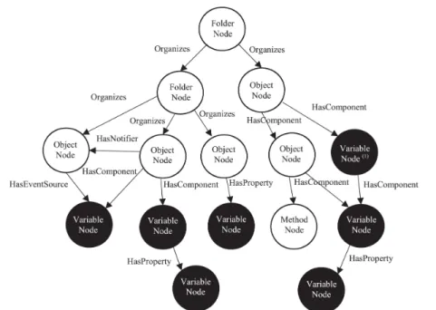
OPC UA specifications define graphical symbols to represent Nodes and References [24]. They are shown by Figure 2.1a and Figure 2.1b, respectively.
(a) Graphical Notation of Nodes (b) Graphical Notation of References Figure 2.1: OPC UA Graphical Notations
It is worth noting that instead of using the HasTypeDefinition Reference to point from an Object or Variable to its ObjectType or VariableType, the name of the TypeDefinition can be added to the text used in the Node. The TypeDefinition shall either be prefixed with ”::” or it is put in italic as the top line as shown in Figure 2.2.
Chapter 2. OPC UA - IEC 62541
Figure 2.2: Example of using a TypeDefinition inside a Node
2.1.5
OPC UA DataType
The Value attribute of an OPC UA Variable is described by a DataType. OPC UA DataType may be Built-in, Enumeration or Structured.
Built-in DataTypes provide for base types like Int32, Boolean, Double; see [27] for the complete list of the Built-in DataTypes avail-able.
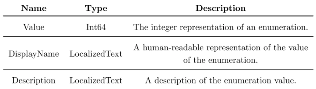
Enumeration DataTypes are used to represent a discrete set of named values. The Value attribute is of Built-in Int32, i.e. an integer, which allows to identify the enumeration value. Enumeration values are maintained by the Enumeration DataType using two mutual ex-clusive OPC UA Properties named EnumStrings and EnumValues. The Value attribute of the EnumStrings Property Node is an array of LocalizedText (for a formal definition of this type see [24]) each of which represents the human-readable representation of an enumerated value; the integer representation of the enumeration value points to a position of the array. The Value attribute of the EnumValues Prop-erty Node is an array too and allows to represent enumerations with integers that are not zero-based or have gaps (e.g., 1, 2, 4). In this case each element of the array is a structure made up by the elements
shown by Table 2.1.
Table 2.1: Structure of each element of the array relevant to Value attribute of EnumValues Property Node
Name Type Description
Value Int64 The integer representation of an enumeration.
DisplayName LocalizedText A human-readable representation of the value of the enumeration.
Description LocalizedText A description of the enumeration value.
Structured DataTypes represent structured data; they are the most powerful construct allowing to specify user-defined (i.e. vendor-specific) complex types. Generally, they are made up by a structure that may contain other Structured and/or Built-in DataTypes.
Transmission of information between OPC UA Client and Server may occur using OPC UA Binary, XML or JSON data encoding [27]. For Built-in DataTypes, the encodings are well defined by the OPC UA specification which defines standard data types giving the encod-ing rules correspondencod-ing to the Built-in DataTypes [25].
For Structured DataTypes, the encodings are exposed in the Ad-dressSpace, so that OPC UA Clients can obtain them in order to decode or encode the data during the communication with the OPC UA Servers. For this reason, different encoding rules may be available for a Structured DataType, depending on the profile used for data transmission; as for example, DefaultBinary encoding is used for the binary data transmission (i.e. OPC UA Binary data encoding). In the following, details about representation of encoding of the Structured
Chapter 2. OPC UA - IEC 62541
DataType will be given considering only the DefaultBinary.
In order to provide the encoding rules, each DataType Node rep-resenting a Structured DataType points to an Object of DataType-EncodingType ObjectType representing the encoding for the specific data transmission (e.g. DefaultBinary Object in the case of binary data transmission).
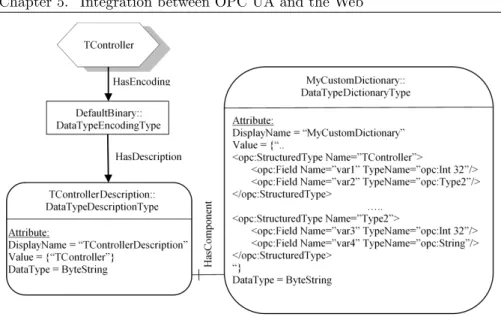
Figure 2.3 shows an example of a vendor-specific Structured DataType named MyType. As it can be seen, this Node is linked to the DefaultBinary Object through an HasEncoding Reference.
Figure 2.3: Example of OPC UA Structured DataType description
HasDescription Reference allows to link the DefaultBinary Ob-ject to an OPC UA Variable of the DataTypeDescriptionType Vari-ableType, named in the example MyTypeDescription. Among its attributes, the Value contains the entry point of the Variable of
DataTypeDictionaryType VariableType which contains the description of the Structured DataType (i.e. its encoding). In the figure, this OPC UA Variable is named MyDictionary. HasComponent Reference is used to link the two variables MyTypeDescription and MyDictionary. As shown by Figure 2.3, the Value attribute of the MyDictionary Variable contains one or more entries called StructuredType. A Struc-turedType contains in turn several Field elements. A Field refers to a component of the Structured DataType and features the attributes Name and TypeName describing the relevant component.
In the example shown by Figure 2.3, only the StructuredType rel-evant to MyType is shown. It is easy to understand that MyType is a structure having two elements named ”var1” and ”var2”. The first element is of a Built-in DataType (i.e. Int32), and the second one is of a Structured DataType, named VarType, defined again in the same MyDictionary Variable as shown by Figure 2.3. As shown, this nested Structured DataType is made up by two elements: ”var3” of Int32 Built-in DataType and ”var4” of String Built-in DataType.
Array of elements belonging to Built-in, Enumeration and Struc-tured DataTypes are allowed for the Value attribute of OPC UA Vari-able Nodes; for this reason, the VariVari-able NodeClass defines two at-tributes named ValueRank and ArrayDimensions which are used to indicate whether the Value attribute of the Variable Node is a scalar or an array and, in the latter case, how many dimensions the array owns; ArrayDimensions is used to specify the maximum supported length for each dimension specified in ValueRank, only in case the Value at-tribute contains an array. It is worth noting that OPC UA allows only array values with elements of the same type, which is specified by the DataType attribute of the OPC UA Variable Node.
Chapter 2. OPC UA - IEC 62541
2.1.6
OPC UA ModellingRules
HasModellingRule Reference is used to describe how instances of types should be created. The source of this Reference is an InstanceDecla-ration. An InstanceDeclaration is an Object, Variable or Method that references a ModellingRule Object with an HasModellingRule Refer-ence and is the TargetNode of a Hierarchical ReferRefer-ence from a type Node or another InstanceDeclaration.
A ModellingRule Object specifies what happens to the In-stanceDeclaration with respect to instances of the OPC UA type. For instance, a Mandatory ModellingRule for a specific InstanceDecla-ration specifies that instances of the OPC UA type referencing the InstanceDeclaration must have a counterpart of that InstanceDeclara-tion. An Optional ModellingRule for a specific InstanceDeclaration, instead, specifies that instances of the OPC UA type may have a coun-terpart of that InstanceDeclaration but it is not required. Mandatory and Optional ModellingRules require that the counterpart of the In-stanceDeclaration has the same BrowseName of the InstanceDeclara-tion.
Other two ModellingRules exist named MandatoryPlaceholder and OptionalPlaceholder. The differences with the previous Mod-ellingRules is that the counterparts of InstanceDeclaration may be more than one, regardless of the BrowseName of the InstanceDec-laration. For this reason, the BrowseName of InstanceDeclarations having the OptionalPlaceholder and MandatoryPlaceholder Mod-ellingRule will be enclosed within angle brackets (e.g. <InstanceDec-larationNames>). Furthermore, in the grapichal representation of OPC UA Nodes used in this thesis, a ModellingRule Object and
rel-evant HasModellingRule Reference are represented inside the source InstanceDeclaration Node only by the kind of ModellingRule Object in square brackets (i.e. [Mandatory], [Optional], [OptionalPlaceholder], [MandatoryPlaceholder]). Figure 2.4 shows an example of the graph-ical notation just described.
Chapter 2. OPC UA - IEC 62541
2.2
OPC UA Services
OPC UA offers many services to allow an OPC UA Client to access to the AddressSpace of OPC UA Servers [26].
2.2.1
OPC UA Discovery Service Set
OPC UA Servers may register themselves with a Discovery Server using the OPC UA RegisterServer Service. OPC UA Clients can later discover any registered Servers by calling the OPC UA FindServers Service on the Discovery Server [26].
2.2.2
OPC UA Session Service Set
Once an OPC Client has found a specific OPC UA Server, it has to create a Session in order to exchange data with the Server [8]. OPC UA Client can establish a Session with the OPC UA Server by using the OPC UA CreateSession Service. Once a Session has been established, it must be activated using the OPC UA ActivateSession Service [26].
2.2.3
OPC UA Browse, Read and Write Services
Once a Session has been created and activated, access to the AddressS-pace maintained by the OPC UA Server can occur.
The simplest way to allow an OPC UA Client to explore the Ad-dressSpace of an OPC UA Server is using the OPC UA Browse Service [26]; given a particular OPC UA Node it allows to discover the Refer-ences and the relevant target Nodes.
OPC UA Read and Write Services allow an OPC UA Client to access to a specific OPC UA Node inside a Session [8, 26].
The Read Service is used to read one or more attributes of one or more Nodes. The OPC UA Client specifies a list of Nodes and the relevant attributes to be read. The function returns a list of the attribute values read. Other elements are passed together with each attribute value; among them, there is the StatusCode. The StatusCode is produced by the OPC UA Server to indicate the conditions under which an attribute value was generated, and thereby can be used as an indicator of the usability of the value. OPC UA defines three values for the StatusCode (which contain a SubCode): Good (it assures that the value is reliable), Uncertain (it indicates that the quality of the value is uncertain for reasons indicated the SubCode), Bad (it means that the value is not usable for reasons indicated by the SubCode). Values that have an uncertain status associated with them shall be used with care since these results might not be valid in all situations. Values with a bad status shall never be used.
The Write Service is used to write values to one or more attribute of one or more Nodes.
2.2.4
OPC UA Subscription and MonitoredItem
Service Sets
Subscriptions and MonitoredItems represent a more sophisticated way to exchange data from OPC UA Server to OPC UA Client. They allow an OPC UA Client to receive cyclic updates of OPC UA Variable values, Node attributes and Events [8, 26].
Chapter 2. OPC UA - IEC 62541
it is associated to a OPC UA Session and is created using the Create-Subscription Service.
MonitoredItems are created using the OPC UA CreateMonitored-Items Service. Each MonitoredItem identifies the item (i.e. Variable value, Node Attribute or OPC UA Event) to be monitored and the Subscription to use to send Notifications when a change is detected. The content of a Notification depends on the changes detected; for example, in the case of changes of OPC UA Variable value, the No-tification contains the new value updated. NoNo-tifications are put in a queue defined inside each MonitoredItem. Size and queuing policy may be defined by the OPC UA Client for each MonitoredItem queue. Notification are packaged into NotificationMessages for transfer to the OPC UA Client.
MonitoredItems have several settings among which there is the Sampling Interval which defines the rate at which it checks for changes in the Variable values, Node attributes and Events. Only for the OPC UA Variable Node, an attribute called MinimumSamplingInterval is defined specifying the lower bound value that the sampling interval can assume for each single Variable value.
Considering a MonitoredItem associated to an OPC UA Variable, in order to detect a Variable value change, several filters are avail-able. Among them, the DataChangeFilter exists. DataChangeFilter features an important parameter, called trigger, which specifies the conditions under which a Notification must be produced. The default value of the trigger parameter is that a Notification is produced if a change in the Variable value or a change in the associated Status-Code is detected. Changes in the value may be generic (i.e., what-ever changes), or it may be specified by another parameter of the
DataChangeFilter, called DeadbandType; it may assume three possi-ble values: None (i.e., no rule is defined for the changes of Variapossi-ble values), AbsoluteDeadBand and PercentDeadband. According to the AbsoluteDeadband [26], a change in the OPC UA Variable value is detected when the absolute value of the difference between the last value (that stored in the queue) and the current value of the OPC UA Variable is greater than a parameter called AbsoluteDeadband, fixed by the OPC UA Client. In other terms, a Notification is produced if (2.1) is verified.
|lastcachedvalue − currentvalue| > AbsoluteDeadband (2.1) The AbsoluteDeadband can be applied only to Variable of Numeric type (i.e., Integer, Unsigned Integer, Float and Double).
The PercentDeadband [28] can be applied only for OPC UA Vari-ables of Numeric Type for which a range of the possible values has been defined inside the OPC UA Server. This range is called EU-Range. In the case of Numeric Variable with an EURange, the OPC UA Client specifies a deadbandValue and a Notification is produced if (2.2) is verified.
|lastcachedvalue − currentvalue| > deadbandV alue
100 ∗ EU Range (2.2) Each Subscription features a PublishingInterval, which defines the interval at which the OPC UA Server clears all the MonitoredItem queues contained in the Subscription and conveys their contents (i.e., Notifications) into a NotificationMessage to be sent to the OPC UA Client.
Chapter 2. OPC UA - IEC 62541
Transmission of NotificationMessages by OPC UA Server is trig-gered by Publish requests sent by OPC UA Client [8, 26]. The OPC UA Server enqueues all the Publish requests received until a Notifi-cationMessage is ready (according to the PublishingInterval, as said before). When this occurs, the NotificationMessage is sent back to the OPC UA Client through a Publish response. For each Publish request sent by the OPC UA Client, exactly one NotificationMessage is transmitted by the OPC UA Server through a Publish response.
2.3
OPC UA Security
OPC UA gives a lot of importance to the secure communication be-tween OPC UA Client and Server. A Secure Session must be created on the top of a Secure Channel, which may be featured by different levels of security, through the choice of the so-called Endpoints [8, 29]. Secure Channel is established to guarantee confidentially, integrity and application authentication. When a Secure Channel has been es-tablished, a Secure Session may be created on its top between OPC UA Client and Server to guarantee user authentication and authorization. Creation of both Secure Channel and Secure Session is based on the use of X.509 certificates issued by a certification authority (CA). Among these certificates, there is the OPC UA Application Instance Certificate, which identifies the installation of an OPC UA product inside an OPC UA Client and Server. It is used during the creation of a Secure Channel.
Each OPC UA Server offers several Endpoints, each of which groups different attributes. Among them, there are: the URL of the
Endpoint, the Application Instance Certificate of the OPC UA Server, the Security Policy (which is the set of algorithms available for the implementation of the secure mechanisms for confidentially and/or in-tegrity like Basic128Rsa15 or Basic256) and the Security Mode (which may enable both digital signature and encryption mechanisms, only digital signature mechanism or none of them). Before the creation of the Secure Channel, the OPC UA Client chooses the Endpoint of the OPC UA Server with the desired features. For example, let us consider an OPC UA Client who wants to use both digital signature and encryption, and let us assume that he wants to realise the digi-tal signature with sha1 algorithm and aes128 for encryption [29]. In this case, the OPC UA Client must look for an Endpoint featuring Basic128Rsa15 as Security Policy, and a Security Mode which enables both digital signature and encryption (it is important to recall that Basic128Rsa15 is a suite of security algorithms that include aes128 for encryption and sha1 for authentication). In order that an OPC UA Client may discover the available Endpoints of a specific OPC UA Server, OPC UA GetEndpoints Service can be used [26]; it gives the list of the Endpoints and the relevant features available for a particular OPC UA Server.
OPC UA Client create a Secure Channel using the OPC UA OpenSecureChannel Service, specifying the URL of the preferred End-point [8, 26]; this service also allows the OPC UA Client to send its Application Instance Certificate to the Server. If the certificate is ap-proved by the OPC UA Server, the Secure Channel is created. It is a logical connection between a single OPC UA Client and a single OPC UA Server, which maintains a set of keys known only to the Client and Server; these keys are used to authenticate and encrypt messages
Chapter 2. OPC UA - IEC 62541
sent across the network.
After Secure Channel has been established, OPC UA Client starts to establish a Secure Session using the services described in subsec-tion 2.2.2. First of all, the Session is created using the OPC UA Cre-ateSession Service. Once the Session has been established, the OPC UA Client uses the OPC UA Service ActivateSession to send the user credentials to the Server. It is worth noting that user credentials may be represented by another certificate or by a pair username/password.
2.4
OPC UA for Devices
In the current automation systems, devices from many different manu-facturers must be integrated resulting in effort for installation, version management and device operation. This challenge can be faced best with an open and standardised device model. For this reason, OPC UA has defined a specification called OPC UA for Devices - Compan-ion SpecificatCompan-ion [30], to define the informatCompan-ion model associated with Devices; it is made up by three models which build upon each other:
• The (base) Device Model is intended to provide a unified view of devices irrespective of the underlying device protocols. • The Device Communication Model adds Network and
Connec-tion informaConnec-tion elements so that communicaConnec-tion topologies can be created.
• The Device Integration (DI) Host Model allows reflecting the topology of the automation system with the devices as well as the connecting communication networks.
In the following, an overview of the Device Model will be given in order to better understand the content of the thesis.
2.4.1
OPC UA Device Model
The Device Model defines several elements, as shown by Figure 2.5 taken from the OPC UA Specification [30].
Figure 2.5: OPC UA Device Model
In the following, only those necessary for the proper understanding of the thesis will be deepened.
2.4.1.1 TopologyElementType ObjectType
TopologyElementType is the base ObjectType for elements in a device topology. This ObjectType is abstract and defines the basic infor-mation components for all configurable elements in a device topology. Figure 2.6 shows the TopologyElementType component.
Chapter 2. OPC UA - IEC 62541
Figure 2.6: OPC UA TopologyElementType ObjectType
All elements in a topology may have Parameters and Methods. Pa-rameters are modelled with OPC UA DataVariable nodes. If such an element has Parameters they are kept in an Object called Parame-terSet as a flat list of Parameters. If it has Methods they are kept the same way in an Object called MethodSet. Both ParameterSet and MethodSet are target of a an HasComponent Reference starting from the TopologyElement Object.
FunctionalGroups can be used to organise the Parameters and Methods to reflect the structure of the TopologyElement. A Func-tionalGroup Node is an instance of the FuncFunc-tionalGroupType
Object-Type, a subtype of FolderType ObjectType. TopologyElements may have an arbitrary number of FunctionalGroups to organise Parameters and Methods. As for example, a FunctionalGroup called Identification shall be used to organise Parameters for identification of this Topol-ogyElement. It is worth noting that the same Parameter or Method might be referenced from more than one FunctionalGroup.
2.4.1.2 DeviceType ObjectType
The abstract DeviceType ObjectType provides a general type defini-tion for any Device. It is a subtype of TopologyElementType Ob-jectType. A Device Node (i.e. an instance of a concrete subtype of DeviceType) may have Parameters, Methods, and FunctionalGroups as defined for the TopologyElementTypeDevices.
DeviceType defines several OPC UA Properties, providing a way for a Client to get common Device information, among which: Softwar-eRevision (which provides the revision level of the software/firmware of the device), Model (which provides the model name of the Device) and Manufacturer (which provides the name of the company that manufactured the device).
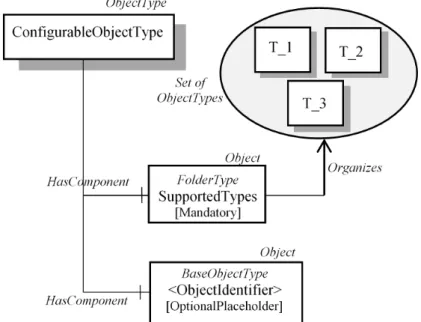
2.4.1.3 ConfigurableObjectType ObjectType
ConfigurableObjectType is used as a general means to create modular topology units. If needed, an instance of this type will be added to the head object of the modular unit.
OPC UA specification [30] defines a generic pattern to expose and configure components, named Configurable Component pattern. This pattern is based on the following principles:
Chapter 2. OPC UA - IEC 62541
• A ConfigurableObject shall contain a folder called Supported-Types that references the list of subtypes of BaseObjectType available for configuring components. The Types are referenced using Organizes References.
• The instances of the available Types shall be components of the ConfigurableObject (through HasComponent References). Figure 2.7 shows the ConfigurableObjectType ObjectType.
CHAPTER
THREE
JAVASCRIPT OBJECT NOTATION (JSON)
DATA INTERCHANGE FORMAT
In the last few years, JSON (JavaScript Object Notation) [31, 32] has achieved remarkable popularity as the main format for the represen-tation and the exchange of information over the modern web.
3.1
JSON base types
JSON is a data format based on the data types of the JavaScript pro-gramming language. JSON can represent four primitive types (string, number, boolean and null) and two structured types (object and ar-ray). In particular, the following base types are defined [31, 32]:
• String: a sequence of Unicode character included between double quotes.
using decimal digits. It contains an integer component that may be prefixed with an optional minus sign, which may be followed by a fraction part and/or an exponent part. A fraction part is a decimal point followed by one or more digits. An exponent part begins with the letter E in upper or lower case, which may be followed by a plus or minus sign. The E and optional sign are followed by one or more digits.
• Literal names: can assume only the values true, false and null. This JSON base type is used to represent both boolean (using true and false) and null (null ) primitive types.
• Object : a sequence of key/value pairs between curly brackets where key and value are separated by colon and pairs are sepa-rated by commas; a key must be a string whilst a value must be of a JSON base type.
• Array: an ordered collection of values between square brackets where values are separated by commas. As for JSON object, a value must be of a JSON base type.
3.1.1
JSON Example
As an example, let us consider the JSON document shown by List-ing 3.1. It contains a JSON object representList-ing the temperature val-ues measured during to the last 24 hours in Rome (Italy), assuming a sampling interval of 6 hours (i.e. only four temperature values are produced every day).
The JSON object is made up by four key/value pairs. The keys of the pairs are: ”country”, ”city”, ”isReliable” and
Chapter 3. JavaScript Object Notation (JSON) Data Interchange Format
”last24hTemperatures”; the relevant values are of JSON string base type for ”country” and ”city”, JSON literal names base type for ”is-Reliable” and JSON array base type for ”last24hTemperatures”. The boolean value in ”isReliable” indicates if the temperature measure-ments contained in the document are reliable or not. The JSON array base type relevant to the ”last24htemperatures” key contains the tem-peratures of the last 24 hours, measured every 6 hours. For this reason, the array contains four JSON objects, each of which is made up by two key/value pairs where the keys are ”timestamp” and ”tempera-ture” and the JSON base types are string and number, respectively. They allow to represent the timestamp and the temperature value for each measurement done. This example illustrates the simplicity and readability of a JSON document, which partially explains its fast adoption. { " country " : " Italy " , " city " : " Rome " , " isReliable " : true , " last24hTemperatures " : [ { " timestamp " : " 14/05/2018 00:30:00 " , " temperature " : 21 } , { " timestamp " : " 14/05/2018 06:30:00 " , " temperature " : 22 } , { " timestamp " : " 14/05/2018 12:30:00 " ,
" temperature " : 30 } , { " timestamp " : " 14/05/2018 18:30:00 " , " temperature " : 26 } ] }
Listing 3.1: JSON Example
3.2
JSON Schema
With the popularity of JSON it was soon noted that in many scenarios one can benefit from a declarative way of specifying a schema for JSON documents. For instance, in the public API scenario one could use a schema to avoid receiving malformed API calls that may affect the inner engine of the application. A declarative schema specification would also give developers a standardised language to specify what types of JSON documents are accepted as inputs and outputs by their API.
JSON Schema [33, 34, 35] is a simple schema language that allows users to constrain the structure of JSON documents and provides a framework for verifying the integrity of the requests and their compli-ance to the API.
JSON schema is represented as JSON objects. A JSON object may be empty (i.e., “{}”) or it may contain a number of key/value pairs having special meanings. An empty JSON object validates every JSON document, whilst the second format validates a JSON document
Chapter 3. JavaScript Object Notation (JSON) Data Interchange Format
according to the rules associated to each key specified in the JSON Schema. Among these keys there are:
• ”$schema”: it is used to specify if the JSON document is a JSON Schema. It also specifies which version of the JSON Schema specification is used.
• ”properties”: the list of key/value pairs that could be present in the JSON document. For each pair, the related JSON Schema is provided.
• ”type”: the type of the JSON Schema or the value type for each key/value pair listed in ”properties”. When it specifies the type of the JSON Schema, it may assumes several values, among which the “object” value; the relevant meaning is that the JSON Schema is a collection of key/value pairs. When ”type” is used to define the value type for each key/value pair, it may indicate if a value is an object, an array or a JSON base type. It is worth noting that specification allows to use integer to restrict numeric values only to integer numbers (number type identifies both integer and real numbers).
• ”enum”: an array containing the allowed enumerated values. • ”required”: an array that specifies which properties must be
present in a JSON document compliant with the schema. The properties here defined must be a subset of the content of ”prop-erties”.
• ”additionalProperties”: a boolean that indicates if different properties from those specified in ”properties” are allowed.
As an example, let us consider the JSON Schema shown by List-ing 3.2.
{
" $schema " : " http :// json - schema . org / draft -07/ schema #" , " type " : " object " ,
" properties " : {
" country " : { " type " : " string " } , " city " : { " type " : " string " } ,
" isReliable " : { " type " : " boolean " } , " last24hTemperatures " : {
" type " : " array " , " items " : {
" type " : " object " , " properties " : {
" timestamp " : { " type " : " string " } , " temperature " : { " type " : " number " } } ,
" required " : [ " timestamp " , " temperature " ] , " additionalProperties " : f a l s e
} } } ,
" required " : [ " country " , " city " , " isReliable " , " last24hTemperatures " ] ,
" additionalProperties " : f a l s e }
Listing 3.2: JSON Schema Example validating the JSON Example shown in Listing 3.1
It validates any JSON document made up by key/value pairs where keys are ”country”, ”city”, ”isReliable” and ”last24hTemperatures”
Chapter 3. JavaScript Object Notation (JSON) Data Interchange Format
and values are string for ”country” and ”city”, boolean for ”isReliable” and array for ”last24hTemperatures”. In turn, the JSON Schema specifies that each element of the array ”last24hTemperatures” is an object made up by two key/value pairs where keys are ”timestamp” and ”temperature” with string and number values, respectively.
All the four properties specified by the JSON Schema (i.e. ”coun-try”, ”city”, ”isReliable” and ”last24hTemperatures”) are mandatory due to their presence in the ”required” property. Furhtermore, other key/value pairs are not allowed due to the property ”additionalProp-erties” set to false. For the same reason each object inside the array ”last24hTemperature” must be made up by the two properties ”times-tamp” and ”temperature” and no additional properties are allowed.
The JSON document seen before in Listing 3.1 is correctly vali-dated by the JSON Schema of Listing 3.2.
CHAPTER
FOUR
OPEN CONNECTIVITY FOUNDATION (OCF)
OCF specifications [36] are based on the REpresentational State Transfer (REST) architecture style [11]. The OCF specifications en-able interoperability between heterogeneous devices acting as OCF Clients and devices acting as OCF Servers. The notion of client and server is realised through roles; an OCF Server exposes hosted re-sources, whilst an OCF Client accesses resources on a server through RESTful operations. Data exchange between OCF Client and OCF Server occurs in JSON format [31].
4.1
OCF Resource Model
OCF defines the OCF Resource Model to enable the interoperability and to provide consistency between devices in OCF ecosystem [36]. The OCF Resource Model is based on the concepts of Device and Resource. According to the OCF Core Specification [37], a Device
models a logical entity (e.g., corresponding to a real device) whilst a Resource is the representation of a component of a Device (e.g., a sensor in a smartphone).
An OCF Resource is an instance of one or more OCF Resource Types. Each Resource Type defines a set of properties exposed by the Resource. A Resource is addressed using URI and contains properties. Properties are represented as key/value pairs of a JSON object and are defined using OCF data types derived from JSON base types. According to [37], OCF adopts the same JSON base types described in Section 3.1, with the exception of ”true” and ”false” value that in JSON are defined by the literal name type but in OCF are mapped in OCF boolean data type (values ”true” and ”false” are left unaltered). The properties of a Resource represent the state of the Resource itself. In addition, a Resource declare a set of OCF Interfaces. Each Interface specifies how is possible to interact with the Resource itself.
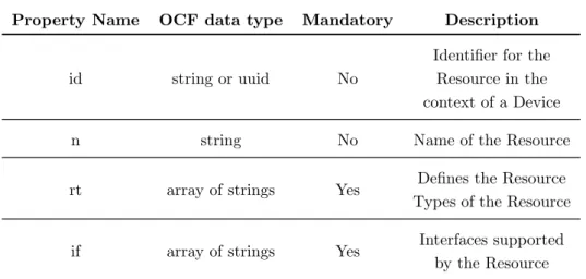
OCF specification defines several common properties which must be present in a Resource. They are specified by the ”oic.core” Re-source Type, and consist of an unique identifier for the ReRe-source in the context of a Device (id), the name of the Resource (n), the Re-source Types (rt) and the Interfaces (if) supported by the ReRe-source. The properties of Resource Type ”oic.core” must be present in every JSON object representing an OCF Resource and are summarised in Table 4.1.
Chapter 4. Open Connectivity Foundation (OCF)
Table 4.1: OCF Common Properties defined by ”oic.core” Resource Type
Property Name OCF data type Mandatory Description
id string or uuid No
Identifier for the Resource in the context of a Device n string No Name of the Resource
rt array of strings Yes Defines the Resource Types of the Resource
if array of strings Yes Interfaces supported by the Resource
OCF specifies that a Resource can be related to another Resource through an OCF Link [37]. A Link consists of a set of parameters. The ”rel” parameter specifies the kind of relationship of a Link; if it is not provided, a value of ”rel” = ”hosts” shall be assumed. The ”href” parameter specifies the target URI of the Resource pointed by the Link. The context URI of a Link is implicitly the URI of the Resource containing the Link itself unless the Link specifies the ”anchor” param-eter. The ”anchor” parameter is used to change the context URI of the Link, in the sense that the relationship with the target URI is based on the anchor URI. As an example, consider a Resource representing a floor containing Links pointing to the Resources representing the rooms in the floor. If each room contain lights, these may be defined in the Resource representing the floor as Links having the ”anchor” parameter set to the URI of the Resources representing the rooms containing the lights. Another important parameter is ”p” (Policy)
which defines rules for correctly accessing a Resource referenced by the target URI. One of these rules, named Observable, may be used to notify the OCF Client on state change of the target Resource.
A Link is always owned by the source Resource, and a Resource with properties and Links is named Collection. Properties of an OCF Collection are defined by the Resource Type ”oic.wk.col”. Among these properties, ”links” is used to gather every Link having as source the Collection itself.
According to OCF specifications, a Device belongs to a Device Type. A Device Type is identified by a string; also a Device Name is associated to a Device Type for informative purpose. A Device Type mandates the list of minimum OCF Resources that a Device of this type must expose; a Device may include other Resources, but the implementation of those specified by its Device Type is mandatory.
In order to enable the functional interaction between OCF Client and OCF Server, OCF mandates a list of core Resources that must be supported and exposed by a Device. Specifically, OCF defines three well-known Resources in an OCF Device. These Resources are addressed in the context of the OCF Device using the predefined URIs ”/oic/p”, ”/oic/d” and ”/oic/res” and belongs to the OCF Resource Types named ”oic.wk.p”, ”oic.wk.d” and ”oic.wk.res”, respectively.
The Resource addressed by ”/oic/p” URI represents the physical platform hosting the physical device. It is used to expose information about platform like vendor name or software version.
The Resource addressed by ”/oic/d” URI represents the device and its properties. Properties of this Resource are defined by the Resource Type ”oic.wk.d”. These properties provide information about the de-vices as: a localized description of the device in one or more language
Chapter 4. Open Connectivity Foundation (OCF)
(ld), the software version (sv), the manufacturer name (dmn) and the model number (dmno). It is worth noting that the ”rt” property of this Resource includes also the Device Type of the device represented, alongside the Resource Type ”oic.wk.d”.
The Resource addressed by ”/oic/res” URI is the entry point for all the Resources exposed by the OCF Device. It contains OCF Links to each Resource owned by the Device.
In the following, an example of an OCF Device Type will be given. Table 4.2 points out its description according to the formalism used in OCF specifications, giving a Device Name and the string which identifies the Device Type (i.e. ”x.my.device”).
Table 4.2: OCF Device Type Example
Device Name Device Type Required Resource Name
Required Resource Type MyDevice ”x.my.device” MyResource ”x.my.resource”
According to Table 4.2, each Device of this type must implement a Resource of ”x.my.resource”. Figure 4.1 shows an instance of this Device Type.
For each Resource, only URI and ”rt” property are shown. The Resource containing the Device information (addressed by ”/oic/d” URI) contains two elements in the ”rt” property; one of these is the ”x.my.device” string representing the Device Type in Table 4.2.
An OCF Device can represent a device made up by subdevices. In this case, an OCF Device can expose Resources representing the subdevices. A Resource of this kind belongs to a Device Type (i.e. its ”rt” property must contain a Device Type) and shall expose the
Figure 4.1: OCF Device instance of ”x.my.device” Device Type
properties defined by ”oic.wk.d” Resource Type. Furthermore, if the Resource representing a subdevice is also a Collection (i.e. it has the ”oic.wk.col” Resource Type in its ”rt” property), it shall link manda-tory Resources specified by the Device Type.
Figure 4.2 shows an example of a Device made up by a subdevice. The OCF Device represented in this figure is the same shown by Fig-ure 4.1, with the addition of a Resource representing a subdevice and addressed by the URI ”/my/subdevice”. As shown, the ”rt” property of this Resource contains three strings: ”oic.wk.d”, ”x.my.device” and ”oic.wk.col”. The first element specifies that this Resource represents a Device whilst the second the relevant Device Type. The last element specifies that this Resource is also a Collection: for this reason it has to link the mandatory OCF Resources defined by the ”x.my.device”
De-Chapter 4. Open Connectivity Foundation (OCF)
vice Type (i.e. a Resource belonging to the ”x.my.resource” Resource Type as defined in Table 4.2).
CHAPTER
FIVE
INTEGRATION BETWEEN OPC UA AND THE
WEB
As pointed out in the Introduction (Chapter 1), this chapter describes a proposal of integration between OPC UA and the Web, enhancing the interoperability between OPC UA and generic users which do not have any knowledge of the standard.
The proposal consists in the definition of a novel data model based on common web data-formats and mapping the OPC UA Information Model. This data model has been defined and used in the implementa-tion of a web platform, called OPC UA Web Platform, able to offer to a generic client a lightweighted interface to OPC UA Servers; lightweight interface is considered both in terms of messages exchanged between client and server and in terms of basic knowledge to be held by a client. The web platform proposed is based on a REST architecture, due to the relevant advantages pointed out in [13].
Several papers and articles describe definition and realization of the OPC UA Web Platform and the relevant data model, from early stages [38, 39, 40] to the actual version described in this chapter [41]. The OPC UA Web Platform has been implemented and the relevant code is available on GitHub [42].
5.1
OPC UA Web Platform Architecture
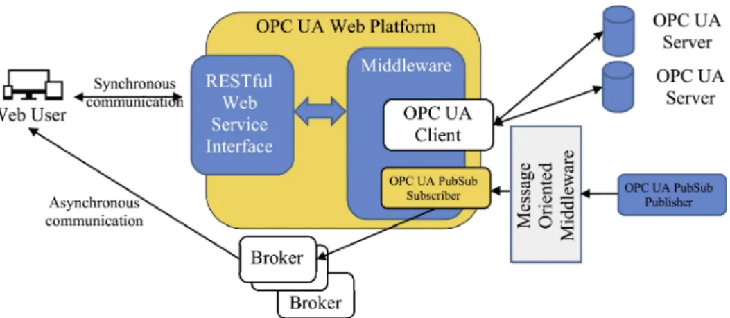
OPC UA Web Platform is based on the adoption of a REST architec-ture and is shown by Figure 5.1.
Figure 5.1: OPC UA Web Platform Architecture
As it can be seen, OPC UA Web Platform offers to a Web User the access to one or more OPC UA Servers. The generic term Web User will identify a generic application which consumes the services offered by the OPC UA Web Platform; these services allow the Web User to access information maintained by OPC UA Servers, without
Chapter 5. Integration between OPC UA and the Web
knowledge of the OPC UA standard and without a real awareness of the presence of OPC UA Servers behind the OPC UA Web Platform, which are seen just as generic servers publishing information. Web User is neither required to be an OPC UA Client nor to implement the OPC UA communication stack (i.e., OPC UA protocol and services). Web User is only constrained to have knowledge of basic concepts detailed in the following subsection.
The OPC UA Web Platform consists of two main modules: • RESTful Web Service Interface. It accepts requests submitted
by an authenticated Web User. Communication between Web User and the OPC UA Web Platform is synchronous as for each Web User’s request through the RESTful Web Service Interface, the OPC UA Web Platform will send a relevant response; it is realised by communication protocols described in the remainder of this section. Due to the adoption of REST, communication between Web User and OPC UA Web Platform is stateless. This means that each Web User’s request is independent from any stored context on the OPC UA Web Platform, and each Web User’s request must contain all the information necessary to the OPC UA Web Platform to accomplish the requested service and to generate the relevant response.
• Middleware. It performs all the operations needed to fulfil each request coming from a Web User; these requests may require data exchange between the Middleware and the available OPC UA Servers. For this reason, the Middleware includes an OPC UA Client used for the access to the OPC UA Servers. Commu-nication between OPC UA Client and OPC UA Servers occurs
according the standard OPC UA communication protocol and services (i.e. using the OPC UA communication stack), as shown by Figure 5.1.
The RESTful Web Service Interface provides several service that will be clearly described in the remainder of this chapter. Among these services it has been foreseen a particular one, called Monitor. It allows Web User to request the activation of a particular asynchronous communication between the platform and the Web User based on Publish/Subscribe Pattern [23]. For this reason, Figure 5.1 shows the presence of a set of Brokers, needed to handle each asynchronous communication requested by a Web User.
Each Web User needing to use the OPC UA Web Platform must be previously registered. During registration, user credentials in terms of username and password must be stored in the OPC UA Web Plat-form. Credentials are issued by a Web User only one time at his first access to the OPC UA Web Platform. The platform validates these credentials and generates a signed token which is returned to the Web User. He will use the signed token received, in each next web service synchronous request issued to the OPC UA Web Platform.
In order to guarantee a secure communication between Web User and OPC UA Web Platform, encryption of data information flow (in-cluding the exchange of the signed token) has been realised by HTTPS [43]. Secure communication between OPC UA Web Platform and each OPC UA Server is realised by the OPC UA Client integrated in the Middleware, through the OPC UA secure mechanisms [29] (explained in Section 2.3).