U
DEPARTMENT OF ELECTR InternationaPOWER CONV
GRID CONNE
UNBALANCE
DEPARTMENT OF ELECTR CoordinatorProf. Ing. Luigi Marletta
UNIVERSITY OF CATANIA
TRICAL, ELECTRONICS AND COMPUTER nal Ph.D. Program in ENERGY (XXVII Cycle
NVERTERS AND CONTR
NECTED MICROGRIDS U
CED OPERATING CONDI
A THESIS SUBMITTED
for the degree of
DOCTOR OF PHILOSOPHY
by
MOIEN A. A. OMAR
TRICAL, ELECTRONICS AND COMPUTER UNIVERSITY OF CATANIA ITALY December, 2014 S Prof. Ing. G ER ENGINEERING le)
ROL FOR
S UNDER
DITIONS
ER ENGINEERING Supervisor . Giuseppe ScarcellaPhD. Thesis: Power Converters and Control for Grid Connected Microgrids under Unbalanced Operating Conditions.
Moien A. A. Omar
© Copyright 2014 All rights reserved. December 2014
University Of Catania
DIEEI-Department of electrical, electronics and computer engineering Catania-Italy
i
DEDICATION
I dedicate this work to the memory of Professor Alfio Consoli for his generous help and immense support during my first steps towards my PhD.
I also dedicate this work to my family, especially to my wife (Eng. Amal Omar) and my children’s (Maram, Leen & Aseel) for their love, patience and sacrifice; to my parents and grandparents for their prayers and encouragement; to my sisters and brothers for their support.
ii
ACKNOWLEDGEMENTS
First, I would like to give my sincere appreciation and thanks to my supervisor Prof. Giuseppe Scarcella, for his support, guidance and kind cooperation throughout the period of the research and thesis development.
I am very grateful to Prof. Luigi Marletta, the coordinator of PhD Program, for his kind cooperation.
I wish to thank also the professors in the Department of Electrical, Electronics and Computer Engineering-DIEEI at university of Catania, Prof. Luigi Fortuna, Prof. Mario Cacciato, Prof. Giacomo Scelba and Prof. Mattia Frasca for their support and encouragement.
I would like to give my thanks and great regards to all my colleagues and friends at university of Catania, especially I am obliged to thank Alessia Avola, Concetta Signorello, Gabriele Fisichella, Mario Pulvirenti, Giovanni Nobile, Angelo Sciacca, Davide Cristaldi, Mohammad Alsayed and all my colleagues and friends whom I met during my stay in Italy.
Finally, my best regards to all my teachers and friends who have assisted me throughout my educational career and life experience.
iii
ABSTRACT
“Power Converters and Control for Grid Connected Microgrids under Unbalanced Operating Conditions”.
Moien A.A. Omar, Ph.D.
Professor. Giuseppe Scarcella, Supervisor.
DIEEI-Department of electrical, electronics and computer engineering. University Of Catania, Catania-Italy, 201.
Nowadays, Renewable Energy Sources (RESs) have become more attractive and affordable due to recent advances in power electronic devices and control systems. Micro-Grids (MGs) represent a new paradigm of electrical grids with Distributed Generation (DG) units: they are generally composed of power converters, RESs, Energy Storage Systems (ESSs), local loads with measurement and control systems.
MGs have the potential to operate in both, grid connected and islanded mode. During islanded mode, ESSs are essential for MGs to enable grid forming control. On the other hand, during grid connected mode, the ESSs allow the MGs to provide different services to the main grid. For example, grid power supporting during peak periods; however, in case of unbalanced operational conditions for MGs, due to single phase loads and single phase generation units, the power exchange between MGs and the main grid will add negative effects to the main grid.
Since the MG is supposed to be grid friendly when connected to the external grid, the unbalanced currents should preferably be handled within the MG. Therefore, the power converters of MGs have to provide the zero sequence and negative sequence currents.
iv
The main objective of this thesis is to obtain grid friendly MGs, in order to improve the functionality of MGs during the grid connected mode, under unbalanced operating conditions.
Power converters with ESSs can be adopted to mitigate the negative effects of unbalanced grid connected MGs. However, suitable control strategies are required. In this thesis, a control strategy based on vector control and symmetrical components is proposed for three-phase four-legs power converter interfaces Energy Storage Batteries (ESBs) to obtain a Multi-Functional Power converter (MFPC), in order to resolve the problems of the unbalanced three phase currents, and to the reactive power compensation.
Several working conditions have been analyzed, and solutions for some common and frequent critical conditions, such as the imbalance of the power system due to single-phase loads and single phase DGs have been presented. Discussions of technical issues like output filter design and four legs VSIs modulation techniques, synchronization, power converters topologies and control have also been discussed.
The proposed control strategy of MFPC is able to mitigate the negative effects of grid connected MGs such as, unbalanced and reactive power compensation. This allows the MGs to become “grid friendly”, even it is working under highly unbalanced and poor power factor conditions, and also performs power management to optimize the MGs supporting services with smart grid functionality.
v
TABLE OF CONTENTS
Chapter 1 Introduction ... 1
1.1 Background ... 1
1.1.1 Electrical Energy ... 1
1.1.2 Electrical Power System (EPS) ... 2
1.1.3 Distributed Generation ... 3
1.1.4 Microgrids ... 5
1.1.5 Smart Grid Concept ... 7
1.2 Asymmetry and Symmetrical Components ... 9
1.2.1 Impacts of asymmetry in Power Systems ... 9
1.2.2 Symmetrical Components ... 10
1.3 Literature Review ... 12
1.4 Problem Description ... 14
1.5 Thesis Objectives ... 15
1.6 Thesis Outline ... 16
Chapter 2 Power Conversion and Interfacing in MGs ... 17
2.1 Power Electronics Converters ... 17
2.1.1 Power Electronics Devices... 17
2.1.2 Power Modules ... 19
2.1.3 Power Conversion Efficiency and Power Density ... 19
2.1.4 Electromagnetic Interference (EMI) ... 20
2.2 Applications of Power Electronic Converters ... 21
2.3 Power Conversion Technology ... 23
2.3.1 DC-DC Power Conversion... 24
2.3.2 DC-AC Conversion for Three Phase, Three Wires Systems ... 27
2.3.3 DC-AC Converters for Three Phase, Four Wires Systems ... 29
2.3.4 Pulse Width Modulation (PWM) ... 31
2.3.4.1 Sine Pulse Width Modulation (SPWM) ... 31
2.3.4.2 Space Vector PWM Modulation (SVM) ... 34
2.3.3.2 Four Legs VSIs Modulation Techniques ... 36
2.3.4 AC Filters for Power Converters ... 38
vi
2.3.4.2 LCL Filter Design ... 39
2.3.4.3 LCL Filter Components ... 41
2.3.4.4 LCL filter transfer Function and frequency response ... 42
2.3.5 Phase Locked Loop ... 43
Chapter 3 Renewable Energy Sources and Energy Storage ... 45
3.1 Overview of Renewable Power Sources ... 45
3.1.1 Solar Energy ... 46
3.1.2 Wind Energy ... 46
3.1.3 Hydro, Geothermal and others ... 46
3.2 Photovoltaic Power Conversion ... 47
3.2.1 Photovoltaic Concept ... 47
3.2.2 Solar Cell Technologies and Efficiencies ... 47
3.2.3 Electrical Model of PV Cell ... 48
3.2.4 Technical Characteristics of Photovoltaic ... 49
3.2.4.1 Voltage and Current Characteristics ... 49
3.2.4.2 The Irradiance and Temperature Effects ... 50
3.2.4.3 PV Maximum Power Point ... 52
3.2.5 PV Modules and Arrays ... 53
3.2.5.1 Model of a PV Module Consisting of n Cells in Series ... 53
3.2.5.2 Model of a PV Panel Consisting of n Cells in Parallel ... 55
3.2.6 Configurations of Grid Connected Photovoltaic Inverters ... 56
3.2.6.1 Central Inverters ... 56
3.2.6.2 String Inverters ... 57
3.2.6.3 Multi-String Inverters ... 57
3.2.6.4 Module Inverters ... 57
3.3 Energy Storage Systems for RESs Integration with the Grid ... 58
3.3.1 Overview of ESSs ... 58
3.3.2 Applications of ESSs for RESs Integration with the Grid ... 58
3.3.3 Energy Storage Technologies ... 59
3.3.4 Energy Storage Batteries ... 60
3.3.5 Technical Characteristics of Batteries ... 61
vii
4.1 Classifications of power converters in MGs ... 62
4.2 Control of Grid Connected Converters ... 63
4.3 Power Balance in Reference Frame ... 64
4.4 Control of Non-Dispatchable Grid Connected VSI ... 65
4.4.1 Grid Parallel Units ... 65
4.4.2 Grid Supporting Units ... 66
4.5 Control of Dispatchable Grid Connected VSI ... 67
4.5.1 Operating Regions of Dispatchable VSIs ... 67
4.5.2 Active and Reactive Power Control of VSIs ... 68
4.6 MFPC Control Strategy Based on Vector Control ... 70
4.6.1 Proposed Control Strategy for MFPC ... 70
4.6.2 Time Domain Simulation of MFPC Control Strategy ... 74
4.6.2.1 System Components and Simulation Description ... 74
4.6.3 Simulation Results of MFPC Control Strategy ... 76
4.6.3.1 Case 1, MFPC During Discharging Mode with Step Response .... 76
4.6.3.2 Case 2, MFPC During Charging and Idle Mode ... 80
4.6.3.3 Case 3, Distributing Power between Unbalanced Phases ... 83
Chapter 5 MFPC for Grid Friendly MGs ... 86
5.1 Unbalanced Operation of MGs ... 86
5.2 Grid Connected MGs Operating Modes ... 87
5.3 Simulation of MGs Operating Modes ... 89
5.3.1 Simulation of MG Supporting Mode (MG-SM) ... 89
5.3.2 Simulation of Grid Supporting Mode (Grid-SM) ... 92
5.4 MFPC for MGs Voltage Quality Improvement ... 95
Chapter 6 Conclusion and Future Work ... 100
6.1 Conclusion ... 100
6.2 Future work ... 101
REFERENCES ... 102
APPENDIX A Mathematical Transformation ... 111
APPENDIX B Sequence Decomposition/Composition ... 112
APPENDIX C Simulink Diagram ... 113
viii
LIST OF TABLES
TABLE PAGE
2.1 Output voltages for three phase converter switching states………… 35
2.2 LCL filter components ……… ………...……… 41
3.1 Comparison of Battery Technologies…… ……… 60
4.1 Classifications of power converters in MGs…… …… ……… 62
4.2 Case 1, simulation parameters… ………...………. 76
4.3 Case 2, simulation parameters………… …….……....………. 80
4.4 Case 3, simulation parameters………… ……..………. 83
5.1 MFPC operating modes……… ………..….. 88
5.2 Simulation parameters of MG-SM……….… ……….. 89
5.3 Simulation parameters of Grid-SM………. 92
5.4 Simulation parameters of voltage quality improvement case………. 95
ix
LIST OF FIGURES
FIGURE PAGE
1.1 Power plants toward distributed power generation…………. …….… 3
1.2 The distributed electrical generation systems……….…..….. …….… 4
1.3 The configuration of a grid interactive ac MG system …….…….….. 6
1.4 Symmetrical components representations………...…….. 11
1.5 MG with unbalanced operation………...……….. … 15
2.1 Power switches availability……….….. 18
2.2 Sectors of power converters applications………..……… 21
2.3 Power converters applications with different ratings……….… 22
2.4 Power electronic conversion..………..…..……….….. 23
2.5 Energy conversion technologies based power converters………..….. 24
2.6 DC/DC Power converters with voltage gain……….………..….. 25
2.7 Bidirectional DC-DC converter……….……… 26
2.8 Basic DC/AC converter topologies……...………….………..…. 28
2.9 VSIs topologies for three phase, four-wires systems……… 30
2.10 VSI Three phase SPWM principle……...……….. 32
2.11 VSI Line and phase voltage waves of PWM………….…………..…. 33
2.12 Three phase, three legs VSI……..……….…….……….…. 34
2.13 Three-phase converter space vector………..……… 35
2.14 Carrier-based pulse width modulation scheme.…… ……… 36
2.15 Gating signals of CPWM for four legs VSI………….………….…… 37
2.16 Filter topologies……….……….……….. 38
2.17 LCL per phase equivalent circuit……….……. 39
2.18 Procedure of LCL filter design………... 40
2.19 THD of MFPC currents…… ……….……….……… 41
2.20 LCL filter frequency response with/without damping………….……. 42
2.21 SRF-PLL block diagram……….. 43
x
3.1 Electricity generation by RESs in Europe (2006 to 2012)…….…….. 45
3.2 PV – cell technologies……….………...……….……. 47
3.3 Solar cell equivalent circuit……….…..…...……… 48
3.4 PV-Module I-V, P-V characteristics……..……….……. 49
3.5 Effects of solar radiation level (a) P-I. (b) P-V curves……… 50
3.6 Effects of the temperature on the (a) P-V. (b) I-V curves………...… 51
3.7 PV-cell, module and array………... 53
3.8 Equivalence evolution of a series PV cells in a module……….. 54
3.9 Equivalent model of a PV module with identical cells in series…….. 55
3.10 Group of identical PV cells connected in parallel………..………….. 55
3.11 Equivalent model of a photovoltaic panel with cells in parallel……... 55
3.12 PV inverters grid connected schemes……… 56
3.13 Power rating ver. Discharge time for various energy storage technologies……… 59 3.14 Voltage as a function of charge-discharge rate and SOC……….. 61
4.1 abc and rotating reference frame vectors.………....……….……. 64
4.2 Structure for grid parallel synchronous rotating frame control……..… 65
4.3 Structure for grid supporting synchronous rotating frame control.…… 66
4.4 VSI real and reactive power operation regions…….………. 67
4.5 Current control block diagram……….….. 68
4.6 Outer control loops for active and reactive power………..…... 69
4.7 The control stages of MFPC in grid connected mode…….…………. 71
4.8 MFPC control loop 71 4.9 Generation of beta by SOGI………..… 72
4.10 Comparison between SOGI and delay technique……….………….… 73
4.11 Tested system considered for simulation……….. 74
4.12 Voltage waveforms of the grid.……….……… 75
4.13 Case 1, positive sequence power of the grid and MFPC………… 77
4.14 Case 1, per phase active and reactive power of MFPC………. 78
4.15 Case 1, sequence components of load currents.………. 78
xi
4.17 Case 1, neutral currents of MFPC and the grid.….….…………..…… 79
4.18 Case 2, positive sequence power of the grid and MFPC..….………… 81
4.19 Case 2, current waveforms of the load, grid and MFPC.. …….…….. 82
4.20 Case 2, neutral currents of MFPC and the grid.……….…….……….. 82
4.21 Case 3, positive sequence power of the loads, MFPC, PV and the grid 84 4.22 Case 3, MFPC active power per phase……… 84
4.23 Case 3, current waveforms of the loads, PV and MFPC.. …….…. 85
4.24 Case 3, neutral currents of MFPC and the grid.……….. 85
5.1 Tested MG for simulation case studies…….… ….………. 86
5.2 Operating modes of grid connected MGs.………. 88
5.3 Positive sequence active power of loads, grid and MFPC (MG-SM). 90 5.4 Positive sequence reactive power of loads, grid and MFPC(MG-SM). 90 5.5 Current waveforms of loads, grid and MFPC (MG-SM)………… 91
5.6 Neutral currents of MG and the grid (MG-SM)………. 91
5.7 Positive sequence active power of loads, grid and MFPC (Grid-SM). 93 5.8 Positive sequence reactive power of loads, grid and MFPC (Grid-SM) 93 5.9 Current waveforms of loads, PV, grid and MFPC (Grid-SM) 94 5.10 Neutral currents of the grid and MG (Grid-SM)……….. 94
5.11 Voltage waveforms at PCC, without compensation..………. 96
5.12 % VUF (-) without compensation …….……… 96
5.13 Current waveforms of loads, PV and the grid, without compensation 96 5.14 Voltage waveforms at PCC, with compensation.………….………. 97
5.15 % VUF (-), with compensation …… …………..….………. 97
5.16 Current waveforms of the loads; PV; grid and MFPC, with comp. 98 5.17 Neutral currents of MG and the grid, with compensation……… 98
5.18 Positive sequence active power of the loads; PV; grid and MFPC… 99 5.19 Positive sequence reactive power of the loads; grid and MFPC…… 99
B-1 Delay block……… 112
B-2 Decomposition block………. 112
B-3 Composition block………. 112
xii
LIST OF ABBREVIATIONS
3D-SVM Three Dimensional Space Vector Modulation 3P4L Three-Phase four-Legs
AC Alternating Current
CAES Compressed Air Energy Storage
CE Clean Energy
CPWM Carrier-based Pulse Width Modulation CS Crystalline Silicon
DC Direct Current
DFIG Duple Fed Induction Generator DG Distributed Generation
DRs Distributed Resources
DSM Demand Side Management
EEI Energy Efficiency Improvements EMI Electromagnetic Interference EMSs Energy Management Systems EPS Electrical Power System
ES Energy Saving
ESBs Energy Storage Batteries ESSs Energy Storage Systems
FACTS Flexible AC Transmission Systems GaN Gallium Nitride
xiii GTO Gate Turn Off Thyristor HVDC High-Voltage Direct Current
IEC International Electrotechnical Commission IGBT Insulated Gate Bipolar Transistor
L V Low Voltage
MFPC Multi-Functional Power Converter
MGs Micro-Grids
MG-SM Microgrid Supporting Mode
MOSFET Metal Oxide Semiconductor Field-Effect Transistor
MPP Maximum Power Point
MPPT Maximum Power Point Tracking NOCT Normal Operating Cell Temperature PCC Point of Coming Coupling
PLL Phase Locked Loop PWM Pulse Width Modulation RESs Renewable Energy Sources
SCADA Supervisory Control And Data Acquisition SCR Silicon Controlled Rectifier
SCT Symmetrical Component Theory
SG Smart Grid
SH Self-Healing
SiC Silicon Carbide
SMES Superconducting Magnetic Energy Storage SOA Safe Operating Area
xiv SOC State of Charge
SOGI Adaptive Second Order Generalized Integrator SPWM Sine Pulse Width Modulation
SRF synchronous rotating frame STC Standard Test Condition
SVM Space Vector PWM Modulation THD Total Harmonic Distortion UPS Uninterruptible Power Supply VAR Volt Ampere Reactive
VRLA Valve Regulated Lead Acid batteries VSI. Voltage Source Inverter
- 1 -
Chapter 1 Introduction
This chapter summaries the motivations and objectives of this work. It gives a general background of electrical energy systems, MGs and smart grid concept. The roles and challenges for developing this field is briefly presented. A review of system configurations and schemes in the electric power system is provided, an explanation of the effects of imbalance in power systems with symmetrical components are explained. Other related concepts are presented and a literature review is also provided, followed by the thesis outline and the scope of research.
1.1 Background
1.1.1 Electrical Energy
Energy plays its continuous role in all spheres of human life, since the industrial revolution started, the world started looking towards productivity and modernity. The main sources of power generation are fossil fuels and nuclear power plants. These sources maybe are sufficient for our generations, however for future generations there is necessity to look for sustainability and finding new solutions to resolve the problem of increasing energy demand and exhaustible fossil fuels resources.
Further, generation of electric power via conventional means is unsustainable, it is considered the main source of greenhouse gases mainly CO2 which harms the
environment drastically and causes global warming, ozone depletion and climate change. Thus one of the major priorities for the worldwide is focusing on the sustainability terms; Renewable Energy (RE), Energy Efficiency Improvements (EEI) and Energy Saving (ES), which are representing an interesting areas for
- 2 -
researchers and engineers to overcome these problems by introducing solutions for keeping the environment and looking for sustainability.
Clean Energy (CE) is generated by RESs like solar energy, wind energy, geothermal and other forms like biomass. These kinds of sources have been used in the past just for special purposes; for supplying rural areas with electricity, wherein supplying these areas from utility grids requires more infrastructures; transmission lines and transformers with more losses and huge investment costs. Nowadays renewable energy is commonly used in different applications mainly in grid connected systems.
1.1.2 Electrical Power System (EPS)
The main challenge of an electrical power system is to supply electricity to the end-users with reliable and efficient way. In traditional power systems, bulky power generation plants supply most of the power in unidirectional power flow and passive electrical distribution network: this makes the energy efficiency improvements a complicated task. Nowadays the world is looking to find new solutions and adds more improvements to this huge market by utilizing small units for power generation in distributed side. As a result passive unidirectional networks become bidirectional active networks as illustrated in Figure 1.1. The energy consumer becomes “prosumer”; who can produce/consume energy with his own DG units and support the main grid with excess energy [1, 2].
As a consequence RESs become more attractive to penetrate and support the main grid to improve the reliability and efficiency of all system by using DG units instead of centralized large generation units.
Figure 1.1 P (a) Traditional pow
1.1.3 Distributed Gen
As mentioned bef free RESs are urgently viable, integrating DG DG units are close to distribution level, mor different sources are c role to improve the ove [3, 4].
- 3 -
Power plants toward distributed power genera ower systems; (b) Decentralized future power
eneration
efore due to energy crisis and environmental p tly needed, as they are environmentally clean an G units with the main grid as shown in Figu to the loads, the losses will decrease at tr oreover the reliability will increase for the ov combined and working together. DGs are pl verall efficiency, sustainability and reliability o
eration: er systems.[1] l pollution carbon and economically gure 1.2. As these transmission and overall system as play a significant y of power system
Figure Electrical power g level of RESs in their flexible nor polluting, can be achieved from i • Efficiency impr • Reduction of en • Voltage profile • Reliability and • Improved powe • Energy security • Reserve require • Saving investm - 4 -
re 1.2 The distributed electrical generation syste r generation sectors are looking for increasing eir electrical energy systems, since they are su
, besides numerous technical and economic installation of DG units such as [5, 6, 7]: provements by losses reduction in the system c environmental pollution. ile improvement. d security enhancement. wer quality. ity enhancement. irements reduction.
tments cost of transmission and distribution inf
stems [1]. ng the penetration sustainable and a ic benefits which components. nfrastructure.
- 5 -
1.1.3.1 Challenges of DGs
Even though aforementioned advantages and benefits of DGs are clear, there are so many challenges poses increasing penetration of RESs integration which needs to be overcome. Main challenges can be summarized in the following:
• Power conversion efficiency.
• Power quality improvement, harmonics, unbalanced. • Energy storage integration.
• Energy management.
There are so many other challenges related to nontechnical issues and standardization, however in this thesis only the technical issues have been considered.
1.1.4 Microgrids
Aforementioned advantages of interconnecting DG units with the main grid encourage interconnecting more units to the main grid. However increasing the penetration level of DGs in electrical networks adds more complexity and poses challenges like disconnection or islanding from the main grid. This requires a new paradigm of active electrical networks which can cover a part of distribution system in low and medium voltage networks: such system is known as “Microgrids” (MGs) [8, 9]. Based on IEEE Std. 1547.4‐2011 [10], MGs are defined “a Distributed Resources (DRs) used for intentional islands. Island systems are EPSs that have DRs and load, and the ability to disconnect from and parallel with the EPS area. As well to achieve the emerging potential and development of DG systems, a MG approach which composites RESs and associated loads with
- 6 -
ESSs in a subsystem must be taken into account as it is shown in Figure 1.3, depicted from [11].
In normal conditions, MGs operate with grid connected mode. During disturbances islanded mode takes place: the generation and corresponding loads can be separated from the distribution system, to isolate the MGs loads from the disturbance without harming the transmission grid’s integrity [12].
Figure 1.3 The configuration of a grid interactive ac MG system.
The cooperation between different MGs or power system clusters leads to manage the generation and the consumption with energy management systems by utilizing information technology and smart meters for matching between RESs, ESSs and load demands. Wherein Smart Grid (SG) concept is arising, it represents a vision for continuous development of electricity market towards more sustainability of EPS.
- 7 -
1.1.5 Smart Grid Concept
In the literature SG is defined by people have different perspectives. For example, the authors in [13] gave a general definition of a SG: it is defined with an intelligent, auto-balancing, self-monitoring power grid, that accepts any power source and transforms its generated power into the end-users, to be used efficiently in different purposes.
SG may also can be defined as a vision for future electric power market to keep going towards more developments and improvements of electrical power sector by utilizing more REs and maintain DG units interconnection to the main grid even under grid abnormalities or blackouts [14]. Energy Management Systems (EMSs) is an attractive solution to manage and distribute the generated power to the customers efficiently with reliability improvements.
EMSs in SGs require interaction between power electronic converters controllers and information technology to resolve the complexity of this technology. This aspect requires introducing new technologies, for example the requirements of technical issues have been changed from using local supervisory control and data acquisition (SCADA) into other recent central data loggers [15, 16]. New solutions instead the limited-capacity communications in SCADA systems like, for example, technology of agents, which is used to send an appropriate alarms to the central computers [14].
Aforementioned technologies provide the SG with data logging, monitoring, prediction, forecasting, SG status, state estimation, protection and energy management. Which allows the SG to be with more controllability, reliability and sustainability. Such power grid responds smartly to the all changes and interacts
- 8 -
with weather conditions, end users behaviors, smart houses, smart meters, Demand Side Management (DSM) and optimal power flow. Indeed smartly means system management intelligently for efficient supply, feasible, sustainable electric power services with more reliability and flexibility [14].
1.1.5.1 Smart Grid Functions
A SG typically performs the following functions [17]:
• Power generation balancing by meeting local loads demand as well as the excess energy that is feeding to the main grid.
• Local loads management: have different categories as critical loads, normal loads and programmable loads.
• Energy storage capability to smooth the intermittent output of RESs and store excess energy and sell this energy in beneficial time.
• integration of technologies smart houses, smart meters and sensors capable of measuring electrical system parameters which are used for control of power converters with a certain accuracy.
• Interacting technical issues with communications and information technology for improving the overall system performance and EMSs.
• Offering and providing solutions for customers requirements and needs in all seasons and times.
• Making the electrical grid a Self-Healing (SH); speedy responding and reacting to real or potential abnormalities.
• Enabling market of electricity by different functions for different users and companies.
- 9 -
1.2 Asymmetry and Symmetrical Components
The unbalanced conditions are very common for Low Voltage (L V) MGs, because of single phase loads and single phase inverters usage. The unbalanced conditions create unbalanced currents circulating between MGs and the main grid, which adds negative affects into grid and the MGs.
1.2.1 Impacts of Asymmetry in Power Systems
Asymmetry in current and voltage add negative effects throughout the process of power delivery. The negative sequence voltage increases heat and losses of induction motors. The negative sequence currents reduce the system efficiency. Asymmetry also affects the power system components with the following [18, 19]: • Protection relays and measuring instruments malfunction.
• Motors and generators : losses, vibration, temperature. • Transmission lines : the capacity of the lines is reduced.
• Transformer: the zero sequence currents circulating in the delta side, causing heat and losses.
According to [20], the International Electrotechnical Commission (IEC) gives a definition of the degrees of the unbalance: the unbalance factor is described in terms of the negative-sequence unbalanced factor and zero-sequence unbalance factor expressed in the following equations.
( )% = × 100 (1-1)
( )% = × 100 (1-2)
- 10 -
1.2.2 Symmetrical Components
The Symmetrical Component Theory (SCT) is widely used in power system fault analysis [21]. According to SCT, a asymmetrical three-phase signal (either current or voltage) can be represented as a sum of positive, negative and zero-sequence components [22] as shown in Figure 1.4. The transformation is given by
= 11
1 1 1
(1-3)
Where X could be V (voltage) or I (current) and α is an operator and has the value of = / , = / (1-4)
= __ _ + __ _ + __ _ (1-5) Where: _ _ _ = 1 1 1 (1-6)
_ _ _ = 1 1 1 (1‐7) _ _ _ = 1 1 11 1 1 1 1 1 (1-8)
Figure 1
- 11 -
- 12 -
1.3 Literature Review
Many research studies have been conducted to investigate and analyze MGs issues with different perspectives; configurations, operation, management and control improvements. Analysis of several MGs configurations AC MGs and DC MGs has been discussed in [23]. The control of islanded MGs, primary, secondary and tertiary control has been analyzed in [24]. The primary control of power converter or droop control has been illustrated in [25]. The control of power converters in stationary reference frame for MGs has been discussed in [26].
In most of these research studies, the analysis has been carried out with the assumption of symmetrical operation or balanced three phase loads in MGs, however, in practice, single phase generation, like rooftop photovoltaic inverters, and single phase residential loads are commonly used in LV MGs. The output power of single phase DGs in LV MGs and residential loads are various and highly dependent on the surrounding conditions and the end-users behaviors. Therefore the unbalanced operations are more common to take place, especially in low voltage MGs with majority of single phase inverters and loads. which will increase the negative sequence currents to flow in MGs and causes serious problems and abnormal operation of sensitive equipment in the MGs [27]. Voltage asymmetry compensation in islanded MGs is proposed in [28]. The authors proposed a control strategy for three wires MGs to resolve the problem of unbalanced voltage in MG by compensating the negative sequence components. The authors didn’t discuss the zero sequence components as they considered three wires MG, however the neutral line is important in case of using single phase inverters and residential single phase loads in MGs.
- 13 -
In case of using delta-wye transformer to provide the neutral bath, the transformer will block the zero sequence currents as these currents will circulate in delta side, however the negative sequence currents will pass with a phase shift of 30 degrees as discussed in [29]. Therefore the transformer will not resolve the problem completely.
Since the MG is supposed to be grid friendly when connected to the external grid, the unbalanced currents should preferably be handled within the MG. Therefore the power converters of MGs have to provide the zero sequence and negative sequence currents [29]. A control strategy for unbalance compensation in MG has been previously described in [30]. The latter control strategy was based on stationary reference frame, and was proposed to mitigate the negative effects of grid connected MGs by using unbalance compensator without discussing PQ control as they didn’t consider ESSs. MGs during islanding mode (not discussed in this work) should be disconnected from the main grid for safety and standard requirements of 1anti-islanding. During islanded mode, grid forming units provide the MG sources and loads with voltage and frequency. The latter units must have ESSs to enable grid forming control. As a result ESSs are essential for any MG, and therefore it can be used with more functions during grid connected mode.
1
Islanding refers to the condition in which a DG continues to power a location even though electrical grid power from the electric utility is no longer present. Islanding can be dangerous to utility workers, for that reason, distributed generators must detect islanding and immediately stop producing power; this is referred to as anti-islanding [31].
- 14 -
In this thesis four-legs power-converter is proposed to be a MFPC: during grid connected mode, mitigates the negative effects and performs other functions based on the grid operator and MG conditions, like supporting the grid with active and reactive power or supporting the MG during power generation shortage, mitigation of voltage drop and voltage rise, increasing DG penetration level and performing power quality improvements. Also it can be used as a grid forming unit during islanded mode.
1.4 Problem Description
In recent years, RESs interconnection with the main grid has become more common due to increased importance of environmental issues and economical benefits for electricity market. as a consequence more distributed power sources based on photovoltaic and wind power generation, in addition to other resources, are installed. Increasing the penetration level of these sources requires more integration of DG units. As a result, problem of system complexity leads to introduce new configurations and schemes of power system networks. MGs are a new paradigm of power system networks and have been extensively studied by researchers to investigate different issues in MGs.
MGs can be used for supporting the main grid during peak period time. On the contrary during off-peak time the main grid is utilized for charging the ESBs of the MGs or supplying it’s local loads in case of power generation shortage or with batteries minimum state of charge. In MGs single-phase generation like PV rooftop can be utilized and different loads can be used by the end-users which can cause the grid currents to be unbalanced with poor power factor as shown in Figure 1.5.
- 15 - Grid PV MFPC Residential loads R L A B C N L.V
Figure 1.5 MG with unbalanced operation.
Unbalanced operation of MGs may lead to serious problems such as unbalanced faults, asymmetrical voltage drops, more losses, loads failure [27, 32]. Thus it is essential, to make MGs friendly with the main grid, improving the quality of power exchange in both power flow directions which allows to improve the overall efficiency and increase the penetration level of DG.
1.5 Thesis Objectives
• Review of power converters in MGs, operation principles and control strategies.
• Perform analysis and simulation of MFPC control strategy for grid connected MGs for unbalanced and reactive power compensation.
• Examine the responses of control strategy with different power management modes for “grid friendly” MGs with unbalanced operation.
• Simulation of different cases, showing the advantages of proposed control strategy, voltage drop mitigation and other related advantages.
- 16 -
1.6 Thesis Outline
This thesis is organized in 6 chapters:
Chapter 1 introduces an overview of electrical energy systems, DGs, MGs and smart grid concepts. Literature review about asymmetrical operation of grid-connected systems, followed by problem description and research objectives is also presented.
Chapter 2 presents a background about power electronic converters including power devices, applications, power converters topologies, issues of power converters interfacing PLLs, and filter interfacing and pulse width modulation for three-legs and four-legs power converters.
Chapter 3 discusses a general overview about RESs and energy storage in MG, photovoltaic dynamic characteristics, PV-inverters and ESS description.
Chapter 4 focuses on control of power converters in MGs, mainly during grid connected mode, Proposes a control strategy for MFPC for grid supporting functions, unbalanced and reactive power compensation and examines the proposed control strategy with different operating modes by time domain simulation.
Chapter 5 employs the proposed MFPC to obtain grid friendly MGs, simulates and investigates different cases and conditions, including reactive power compensation, unbalanced loads, and voltage quality improvements for grid connected MG under unbalanced operating conditions.
- 17 -
Chapter 2 Power Conversion and Interfacing in MGs
In this chapter power conversion technology, power electronic systems, power devices and power converters applications are discussed to fulfill deep understanding of the idea. Power converters topologies and PWM modulation strategies for VSIs are illustrated. AC filters topologies with focusing in LCL filter design and its dynamic behavior analysis. Synchronization with PLLs are described and discussed.
2.1 Power Electronics Converters
The development of power electronic devices contributes substantially in developing of the technology of DG, whereas each DG unit needs to be interconnected with the main grid through power electronic converters to control and improve the output power [33, 34]. In MGs power electronic converters represent the key elements for operation and functionality improvements, the main purposes of using power converters in MGs, are power control, power sharing, RESs interfacing, power quality improvement and energy management.
2.1.1 Power Electronics Devices
Semiconductor switches represent the main part, “the heart” of power
electronic converters. These power devices have distinct characteristics, like switching frequency, Safe Operating Area (SOA), thermal performance and other characteristics. Figure 2.1 shows different power levels and switching frequencies of power devices [35]. Silicon Controlled Rectifier (SCR) and Gate Turn Off Thyristor (GTO) operate up to near 1 kHz. It can be employed in high power converters where the switching frequency is not important. As a result such power converters are bulky with low power density.
Fig
Insulated Gate Semiconductor Field-E ratings. They are used devices are preferable components. IGBT has has very low on-state l a phenomena that calle to relatively high switc Power MOSFETs losses and require ver
- 18 -
igure 2.1 Power switches availability [35].
Bipolar Transistor (IGBT) and power Effect Transistor (MOSFET), has higher swit ed in the lower power applications hence hig le with high switching frequency to reduce the
as lower switching frequency in comparison w e losses “conduction losses” [36]. However IG lled “tailing” which causes extra high turn-off itching losses [37].
Ts on the other hand switch very fast, have ver ery little power for their control. However th
er Metal Oxide itching frequency high speed power the size of passive with MOSFET. It IGBT suffers from ff losses and leads
ery low switching they have a very
- 19 -
high state resistance and thus dissipate a large amount of power during the on-state [36, 37] as a result they are not used for high power applications.
With the increasing power rating of the power converters used in different industrial applications, the high voltage and current require series and parallel configurations of power converters. This needs costly active or passive snubbers and other expenses for cooling. Therefore the need of high-power, high voltage rating devices, operating with high switching frequencies and high limits of junction temperatures are growing, especially for advanced power converters. These new requirements need to look for new materials to overcome silicon based material limitations with wide band gap semiconductors, such as Gallium Nitride (GaN) and Silicon Carbide (SiC) devices [38].
2.1.2 Power Modules
A power semiconductor module may be defined as a device which contains more than one semiconductor chip and provides electric and a heat flux paths [39]. Power electronic systems have become much more compact, cost efficient and reliable, which require advanced device packaging and integration technology.
2.1.3 Power Conversion Efficiency and Power Density
The main concerns in modern power electronic systems are delivering the power with maximum efficiency, minimum cost and high power density (weight reduction).
Power conversion efficiency is a crucial challenge for DG technology. Thus using high efficient power converters for interfacing renewable power sources like (photovoltaic, wind, fuel cells) with the utility grid is strongly recommended to enhance the utilization of these sources.
- 20 -
Passive elements (inductors and capacitors) are used in power converters for filtering out harmonics thereby the Total Harmonic Distortion (THD) of current and voltage is reduced within the standard limits. The size of passive elements is proportional to the switching frequency. Therefore, using high switching frequency devices leads to decrease the size of these elements, reduce the losses, increase the efficiency; as a result the power density of these converters will also increase [40].
2.1.4 Electromagnetic Interference (EMI)
EMI in power electronics is an issue that comes from fast switching, di/dt and
dv/dt increasing at switching periods while time of switching dt is decreasing. EMI noises is a major issue in most power electronic systems due to significant over voltage and leakage current generated by fast switching and stray components of the system. Electromagnetic compatibility for power converters operating at switching frequencies higher than 9 kHz is recommended. This is primarily a cost problem for filtering such noises caused by high switching [41]. In addition over voltages might be created due to high di/dt. They may be created in presence of parasitic inductance in current paths; high dv/dt may creates significant leakage current in magnetic elements and electric motors due to stray capacitive. As mentioned before the switching losses can be reduced by increasing the switching frequency, however fast switching increases EMI noise as dv/dt and di/dt increases. Thus, it is a trade-off between losses reduction and EMI to determine the optimal switching frequency. The other alternative is to reduce stray inductance and capacitance of power electronics systems by using a better layout or bus-bars, interconnection and configuration to suppress the EMI at high switching frequency.
2.2 Applications of Po
Power electronic applications include re Supply (UPS) system compensators, Flexible Current (HVDC) syst frequency heating, ES drives.
Different applicati 2.2. It is clear that the percent with respect to
Figure 2.2
- 21 -
ower Electronic Converters
ic converters have a significant role in diff regulated power supplies (DC and AC), Uninte tems, electronic welding, Volt Ampere R ble AC Transmission Systems (FACTS), High stems, RESs power converters (PV, wind F ESSs, electric vehicles, electrical transporta
ations for power electronic converters are illus he applications of drives and renewable energy to other applications.
2.2 Sectors of power converters applications [4
ifferent industrial nterruptible Power Reactive (VAR) gh-Voltage Direct Fuel cell), high-rtation and motor
lustrated in Figure gy represent large
The ratings of pow as shown in Figure 2. applications, low powe and stack are employed
Figure 2.3 Pow
- 22 -
ower electronic converters vary depending on 2.3. Different rating levels of power convert wer applications employ discrete components, ed for medium and high power applications.
ower converters applications with different ratin
n the applications rters for different ts, power modules
- 23 -
2.3 Power Conversion Technology
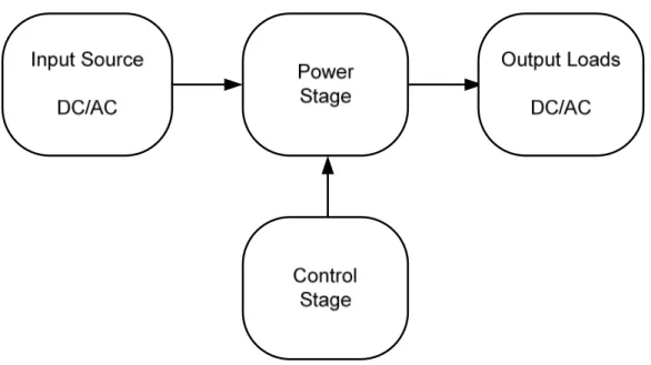
Power conversion process consists of two stages, power and control stages. As shown in Figure 2.4, the power stage is to convert the input power (AC or DC) and deliver it to the output side (AC or DC). The control stage is used for controlling the power converter to synthesis reference output power, by measuring input and output currents and voltages.
Figure 2.4 Power electronic conversion.
Power conversion can be divided into four different categories according to the input and output power forms [38, 43]. In Figure 2.5, four different combinations of power converters can be used for power conversion of renewable energy sources.
• DC-DC converter.
• AC-DC converter (rectifier). • DC-AC converter (inverter). • AC-AC converter.
- 24 -
Figure 2.5 Energy conversion technologies based power converters.
2.3.1 DC-DC Power Conversion
DC/DC power converters are used in renewable energy systems to increase or decrease the DC voltages. Commonly used converters, the buck is used to decrease the voltage, the boost for increasing the voltage and buck-boost for both functions (bidirectional) conversion.
The DC-DC power converters are available with different topologies or circuits [43]; isolated and non-isolated circuits. In Figure 2.6 DC-DC converters with non isolated circuits are shown along function of duty cycle D, with voltage gain. Power MOSFETs represent the ON/OFF switching to achieve desired duty ratio based Volt-Second balance and diode is used for freewheeling the inductor current.
- 25 -
Buck converter is used to decrease the input DC, as shown in Figure 2.6.a, the duty ratio is varied from zero to 1, that means the output voltage less than the input voltage.
a)
b)
c)
Figure 2.6 DC-DC Power converters with voltage gain. (a) buck; (b) boost; (c) buck-boost.
Boost converter on the other hand is used to boost or increase the voltage up to certain limit as shown in Figure 2.6.b. This limitation is due to non ideality of the inductor as can be seen the Vout/Vin=1/(1-D). theoretically as the duty ratio is equal
- 26 -
to 1, the gain will increase to infinity, this is true for ideal converter. In practice the non-ideality of the converter should be considered, so the tradeoff is between the voltage gain and the efficiency of the converter.
Buck-Boost converter also is shown in Figure 2.6.c, MOSFET switches alternately connects the inductor across the power input and output voltages. This converter output with inverse polarity of the input voltage. It can either increase or decrease the voltage magnitude. The conversion ratio is [-D/ (1-D)].
Other topology of buck-boost converter is shown in Figure 2.7 is used for increasing the conversion efficiency [44]. It provides bidirectional power transfer with two operation modes buck and boost.
• Buck mode: In buck operation the power is transferred from Vdc to VB.
• Boost mode: In boost operation, the power is transferred from VB to Vdc.
Figure 2.7 Bidirectional DC-DC converter.
In the bidirectional boost converter control, since T1 and T2 cannot be
switched on simultaneously, a practical control strategy is to turn on one of the two switches per operation mode, i.e. T2 off at the same time T1 is controlled and the
- 27 -
2.3.2 DC-AC Conversion for Three Phase, Three Wires Systems
DC/AC power converters is used in different applications like UPS, motor drive, power system applications. Some of these applications need to control the voltage magnitude and the frequency, which is achievable by using Voltage Source Inverter (VSI). For grid connected RESs the voltage and frequency are synchronized with the grid and working as current sources, however sometimes mainly during isolated or islanded mode the power converter is used to modify and control the output voltage and frequency.
The input of VSI is DC as shown in Figure 2.8.a, it must be greater than the output voltage as it is working as buck converter. VSIs create voltage waveforms at the output and the current waveforms follow the loads requirements or it could be controlled to be leading or lagging currents for reactive power supplying or consuming. CSI (Current Source Inverter) is another topology as shown in Figure 2.8.b. The input is DC current source as a large inductor is connected in series with the DC bus. CSI has disadvantages like bulky and heavy [45, 46, 47]. Figure 2.8.c, shows another Inverter topology with combination of CSI and VSI, it is called impedance-source (z-source inverter). it is used in some applications, it can work in buck and boost operation, but it has more passive components. The economical issue is arising with high power ratings [47]. In this thesis VSI is considered as it is commonly used for renewable energy applications.
- 28 - (a)
(b)
( C )
Figure 2.8 Basic DC/AC converter topologies:
- 29 -
2.3.3 DC-AC Converters for Three Phase, Four Wires Systems
Single phase loads or DG in MGs require 4 wires systems. Therefore unbalanced operation arises. Thus it is required to have power converters that can handle the unbalanced negative and zero sequence currents. In Figure 2.9 different topologies of DC/AC converters are shown for four wires systems [29]. The topology of using three-legs with delta-wye transformer is shown in Figure 2.9.a. Without using transformer usually the neutral wire is connected to the conventional three-phase inverter by splitting the DC-link into two adjacent capacitors as shown in Figure 2.9.b. The problem faced to the split DC-link, is the unequal voltage sharing between the capacitors. This requires large DC link capacitors or an extra voltage balancing control scheme. Another drawback for this configuration, is that the unbalanced and non-linear loads cause neutral currents and can distort the output voltage, while zero sequence current will affect the DC bus or the input. To overcome these drawbacks, the four-legs topology shown in Figure 2.9.c can be used instead of the split DC-link. The fourth leg allows the full control of neutral connection, resulting in better output voltage. The addition of the forth leg also makes a voltage balancing control scheme unnecessary. Such an inverter is called Three-Phase four-Legs (3P4L) [48].
Applications of four-legs power converter is growing and will have a larger market share [49]. Four legs inverter is used for interfacing DG units, as shown in [50, 51]. DGs can work either in islanded or grid connected mode, and such inverter with four-legs provides a three-phase output with a neutral connection. In [52] a four-legs inverter is proposed to resolve power quality problems (active
- 30 -
power filter) for harmonic compensation. It is also employed in (UPS) systems [53], other applications like active rectifier [54] and electrical drive systems [55].
(a)
(b)
(c)
Figure 2.9 VSIs topologies for three phase, four-wires systems: (a) Three legs with transformer; (b) Three-legs with split capacitor;
- 31 -
2.3.4 Pulse Width Modulation (PWM)
PWM is widely used in different power electronic converters. High switching frequency for DC-DC converters can be achieved by PWM to reduce the ripple in output voltage and current. In DC-AC conversion, PWM is used in a different way to control the amplitude and frequency of the output. PWM strategy plays an important role for harmonics and switching losses minimization in power converters. The main goal of any modulation strategy is to obtain a variable output with a maximum fundamental component and minimum harmonics [56].
The Sine Pulse Width Modulation (SPWM) technique is easy implemented therefore is widely used in industrial applications and converters, however the DC bus voltage utilization for SPWM is low. Space Vector Modulation (SVM) is the most popular PWM technique [56, 57, 58]. It is used in three-phase power converters and in comparison with SPWM, SVM gets more DC-bus voltage utilization and generates less harmonics in output. In SVM the reference signals are modified according to the operating conditions of the VSI in every sampling period, which improves the quality of the AC outputs and leads to lower THD [59].
2.3.4.1 Sine Pulse Width Modulation (SPWM)
The SPWM principle is based on the comparison of a carrier signal and pure sinusoidal control signals, as shown in Figure 2.10. For three phase VSI, the three modulating sinusoidal signals, with 120 degrees phase shift, are compared with a triangular waveform or carrier signal which is with higher frequency. The ratio between the amplitude of the control voltages Vc, and the triangular signal peak Vt
is defined as the modulation index m= Vc/Vt where Vc and Vt are respectively the
- 32 -
Figure 2.10 VSI Three phase SPWM principle
By changing the modulation index m, between 0 and 1 which is called the linear region, the widths of pulses vary, which results in variations in the amplitude of the output voltage. The maximum output voltage when (m=1) is given in equation:
= √3
2√2 = 0.61
The inverter switching frequency is constant and equals the carrier signal frequency fc, and the frequency of the control signals fm, determines the frequency
of the output voltage.
Figure 2 Frequency modula the modulating signal voltage of a SWPM inv
Mf is recommend
quarter cycle symme particular a small dc c the PWM is so-called s PWM, in which Mf is modulation frequency between switching loss
- 33 -
2.11 VSI line and phase voltage waves of PWM ulation ratio (Mf) is the ratio between switchin
al frequency, Mf = fc/fm. The frequency spectru
inverter contains harmonics orders around Mf, 2
nded always to be chosen an odd integer num metry), therefore avoiding even-order harm
component, at the output voltage. If Mf is an
d synchronous PWM. On the other hand, there is not an integer number, and it can be emp y ratio is high [37], however with a high valu
sses increasing and harmonic decreasing.
WM
ing frequency and trum of the output
, 2Mf,3Mf.
umber (to ensure rmonics, and in n integer number, re is asynchronous ployed when the ue that trades off
- 34 -
2.3.4.2 Space Vector PWM Modulation (SVM)
Basically SVPWM looks to VSI as one unit and not separate legs like SPWM, VSI has six switches as shown in Figure 2.12. Each leg has two switches and they always switching in complementary fashion, so VSI has eight different switching states, six for active vectors and two for zero vector as shown in Table 2.1.
The active vectors divide the vector plane into 6 sectors as shown in Figure 2.13. The rotating reference vector can be obtained in each switching cycle by switching between the two adjacent active vectors and the null vectors. In general to obtain any vector, the phase angle of the vector should be known to define in which sector the vector exist. In order to maintain the effective switching frequency at a minimal value, the sequence of the toggling between these vectors is organized in such way that only one leg is affected in every step [60].
- 35 -
Figure 2.13 Three-phase converter space vector.
Table 2.1 Output voltages for three phase converter switching states
1 1 0 0 0 1 1 0 1 1 1 0 0 0 0 1 0 1 1 1 0 0 1 0 0 0 1 1 1 0 0 1 0 0 0 1 1 1 1 0 1 0 0 0 1 1 0 1 2 3 13 −13 −23 −13 13 0 0 −13 −23 −13 13 23 −13 0 0 −13 13 23 3 1 −13 −23 0 0
- 36 -
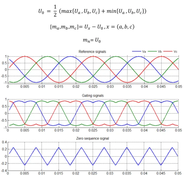
2.3.3.2 Four Legs VSIs Modulation Techniques
Various modulation techniques have been proposed for switching the 3P4L converter. The Three Dimensional Space Vector Modulation (3D-SVM) technique was proposed in [61, 62]. It requires complex calculations for the selection of the switching vectors by employing an αβ0 transformation.
Carrier-based Pulse Width Modulation (CPWM) is another option [63]. It has been shown that CPWM is equivalent to a 3D-SVM but with an easier implementation. Because of that, it was chosen to be used in this work for converting the reference three signals, from the control loops, into four gating signals for the four-legs inverter. Its diagram is shown in Figure 2.14, the three inputs (Ua, Ub and Uc) and the four outputs are the gating signals of 3P4L
converter.
- 37 -
The zero sequence signal can be given with the following :
= 12 ( , , + , , )
[ , , ]= − , = ( , , )
=
- 38 -
2.3.4 AC Filters for Power Converters 2.3.4.1 Filter Topologies
The output power of converters, synthesized by using PWM which has high frequency harmonics, needs to connect AC filter across the converter. AC filters types as shown in Figure 2.16 come with three configurations [64].
Figure 2.16 Filter topologies: a) L-filter ;b) LC-Filter and c) LCL-filter. L-filter is the simplest filter it needs high switching frequency to attenuate the high harmonics sufficiently. LC-filer can be made by shunt capacitor with the inductor so it is a second order filter, it is employed where the load impedance across shunt element is relatively high at and above the switching frequency [64]. Inductor-capacitor-inductor (LCL) filter, as compared with the L filter, the LCL filter, is more attractive because it has ability for higher harmonics attenuation and also it is allow the inverters to work in both islanded and grid connected modes. It is non sensitive regarding the grid impedance, thus it is commonly used with MGs inverters, MGs can operate in both modes: islanded and grid connected. The power converter which will work as universal one suitably uses LCL filter [65,66]. For mentioned advantages it has been employed for our case study.
Due to resonance, LCL filter may lead to unstable operation therefore passive or active damping is required to resolve this issue. Passive damping is obtained by adding a resistor element in series or in parallel and active damping by changing the controller design [66].
- 39 -
2.3.4.2 LCL Filter Design
Figure 2.17 shows an one line diagram of LCL filter. The elements can be defined as inverter inductor, grid side inductor and capacitor, taking into account the damping resistance and inductors resistances.
Figure 2.17 LCL per phase equivalent circuit.
Aforementioned elements can be sized with different approaches mentioned in literature. In all approaches the rating capacity of VSI, switching frequency and output voltage represent main factors for sizing [67]. Step by step approach as illustrated in Figure 2.18 has been used for sizing the LCL filter [68, 69].
Fig An LCL filter is u harmonic standard. Th by using a passive dam
- 40 -
Figure 2.18 Procedure of LCL filter design. s utilized for attenuating the harmonics and me
he instability issue associated with an LCL fil amping element [67].
meeting IEEE 519 filter is dampened
- 41 -
2.3.4.3 LCL Filter Components
LCL filter components have been chosen for MFPC by using step by step procedure as shown in Figure 2.18. The design parameters are: VSI with 30 kVA rating, grid frequency 50 Hz, switching frequency 12150 Hz, output voltage 230 VRMS. The parameters of LCL filter are given in Table 2.2.
Table 2.2 LCL filter components.
Element Value Lf 3e-3 H Cf 30e-6 F Lg 0.1e-3 H Rf 0.1 Ω Rg 0.1 Ω Rd 2 Ω Figure 2.19 THD of MFPC currents.
As shown in Figure 2.19, the THD of MFPC output currents (60 A peak) is 1.12 %, which is below the 5% limit imposed by IEEE-519 Std.
- 42 -
2.3.4.4 LCL filter transfer Function and frequency response
In this section, the transfer function of LCL filter with damped ( ) and without damped ( ) will be described. Based on [69], the transfer function of LCL filters in both cases is written with the following equations with inductors resistances neglecting:
( ) =( ∗ ∗ ) ∗ + ( + ) ∗1
( ) =( ∗ ∗ ) ∗ + ( + ) ∗∗ ∗ + 1 ∗ + +( + ) ∗
Figure 2.20 LCL filter frequency response with/without damping.
As we can see in the Figure 2.20 in the range higher than resonance frequency, the attenuation rate of LCL filter is -60dB/Decay. Also it can be observed how the damping resistance suppress the gain spike, smoothing the response at high frequency −270◦ and to −180◦. -150 -100 -50 0 50 100 150 M a g n it u d e ( d B ) 102 103 104 105 -270 -225 -180 -135 -90 P h a s e ( d e g )
Bode Diagram LCL Filter
Frequency (Hz)
- 43 -
2.3.5 Phase Locked Loop
Phase Locked Loop (PLL), is essential for inverter synchronization with the utility grid. It is a feedback circuit which takes the grid three phase voltages as input signals and the output is the phase angle of one of these phases as shown in Figure 2.21. The phase angle for the other two phases is obtained by assuming that main voltages are symmetrical and the phase shift between the various phases is 120 deg. The output signals are synchronized with the input ones both in frequency and in phase.
PLLs are available mainly with three types for phase tracking: synchronous rotating reference frame (SRF), stationary reference frame and zero crossing. The first one; SRF PLL gives the best performance under non-ideal grid conditions therefore it is commonly used with DGs [70, 71, 72].
Figure 2.21 SRF-PLL block diagram.
Basically SRF-PLL Algorithm starts from measuring grid voltages and performs Park’s transformation, abc to dq (see Appendix A). By using a PI controller the ’phase-lock’ is realized by setting Vq=0. The output of the PI controller is the grid frequency, which, added to the feed-forward frequency and then integrated, provides the grid phase angle.
- 44 -
The transfer function of Proportional Integral (PI) controller is given by the following:
( ) = ∗ +
Kp=250; Ti= 0.004s
Figure 2.22 shows the behavior of the SRF-PLL, simulated by using Matlab Simulink.
Chapter 3 Ren
In this chapter a system characteristics ESSs for grid integr characteristics have be3.1 Overview of Rene
RE generated by s hydro, wave and tida renewable sources in E
Figure 3.1 Elec
- 45 -
enewable Energy Sources and Energy
a general overview of RE is briefly discusse s and modeling with PV inverter configuration gration overview, applications, technologies been illustrated.newable Power Sources
y sustainable sources such as solar, wind, biom dal. Figure 3.1 shows the generated energy Europe.
ectricity generation by RESs in Europe (2006 t
gy Storage
ssed, photovoltaic ions are explained. ies and technicalmass, geothermal, gy from different