...
. ... ... ... ... ... ... ... ... ... ...
...
with flat-panel ground heat exchangers
*Corresponding author: [email protected]
Michele Bottarelli*
University of Ferrara, V. Quartieri 8
– 44121 Ferrara, Italy
Abstract
The paper reports and analysis the preliminary tests of a dual-source heat pump prototype (DSHP) as experimental air-conditioning system for a room at the University of Ferrara (UNIFE), Italy. The proto-type is composed of a common air-to-air heat pump, a geothermal closed loop, and a novel kit for coup-ling the air-source heat pump with the closed loop. The kit links the refrigerant circuit with a plate heat exchanger coupled with the closed loop, and automatizes the switching between air and ground by mean of a control unit which pilots valves according rules based on air-ground temperature and air humidity. As ground heat exchanger (GHE), the Flat-Panel patented by UNIFE is chosen due to its higher per-formance in comparison with similar shallow and horizontal GHEs. Moreover, its flat shape allows installations in narrow trenches, minimizing the digging and therefore the overall costs. By mean of a comprehensive monitoring system, the behaviour of the duo prototype-closed loop was monitored for a whole year in terms of temperatures, pressures, flow rate, electricity supply, and heat flux. Even if the first year was used for the optimization of the switching rules, the comparison with traditional air-source systems evidences the better behaviour of the DSHP, and therefore the overall energy saving. Having the possibility to partialize the closed loop, the performance was also evaluated in under/overloaded condi-tions of the Flat-Panels, to implement new control criteria matching DSHP control rules with closed loop length for a dynamic design of the overall system.
Keywords: dual-source heat pump; flat-panel ground heat exchanger; experimental test; energy performance
Received 7 November 2018; revised 4 January 2019; editorial decision 6 January 2019; accepted 10 January 2019
1 INTRODUCTION
Reversible air-source heat pumps (ASHPs) and ground coupled heat pumps (GCHPs) are regarded as viable and efficient tech-nology for space cooling and heating of residential and commer-cial buildings [1]. ASHPs have a low initial installation cost and are easily applicable; however, during winter operations as well as under cold and humid weather condition, this technology is subjected to frosting on the evaporator [2,3]. This phenomenon produces both reduction in efficiency and heating capacity, and wastes more than 12% of full seasonal heating load [4, 5]. GCHPs can achieve higher efficiency than ASHPs by using the underground thermal energy stored, which is related to the ground temperature and its heat capacity [6–8]. GCHPs can be installed at any location where drilling or earth trenching is feasible. Besides the high efficiency, the cost-effectiveness is
penalized by the ground coupled heat exchangers (GHEs), which are recognized as the least efficient component. Because the heat transfer in the ground is mainly conductive, the very low soil thermal diffusivity heavily affects the GHEs sizing, and therefore the overall initial costs.
GHEs usually consist of a buried piping network, which can be installed in vertical boreholes or in shallow horizontal trenches (also referred as VGHEs and HGHEs, respectively). GCHPs based on VGHEs benefit from the relatively stable temperature in the deep ground provided by the geothermal energy. A substantial load imbalance may result in a tempera-ture rise or fall in the ground over a number of years, fre-quently solved by designers by mean of a significantly oversizing of the VGHE [9–12]. However, this can ultimately reduce the economic feasibility of the project [13]. On the contrary, GCHPs employing HGHEs use the shallow soil
International Journal of Low-Carbon Technologies 2019, 14, 247–255 © The Author(s) 2019. Published by Oxford University Press.
mainly as a seasonal thermal source/sink. A HGHE is gener-ally installed in the upper 2 m of the ground soil, and the per-formances of a GCHP are therefore affected by the ambient conditions [14]. In view of this, HGHEs received much less attention than VGHEs with respect to research efforts. But, despite a rather low effectiveness in heat transfer for conven-tional HGHE types, the excavation process remains fairly straightforward; local operators can usually be employed and the excavated soil can be directly used for backfilling. Additionally, installation at shallow depths allows considerable freedom in the design of the heat exchanger geometry, con-trary to the VGHEs [15, 16]. Moreover, the geologic charac-terization is relatively easy, and not so essential as for VGHEs [17]. In view of these distinctive advantages, the research interest in the development of advanced HGHEs has been growing to address the relevant drawbacks [16]. In summary, shallow HGHEs possess excellent potential in coupling with GCHP systems, and contrary to VGHEs, the opportunities for improvement and advancement in performance remain sig-nificant and remarkable, because in mild climate this technol-ogy does not suffer thermal imbalance issues [18].
Nevertheless, the payback time of the GHE installation cost remains too long to justify the effort [19]. Therefore, even with an efficient and cheap GHE solution, it could be profitable to exploit on demand an alternative thermal source, such as the air, to reduce the ground energy load and therefore the GHE installation cost, since related to a shorter closed loop. That is the main idea of the hybrid air-ground heat pump system, so called dual-source heat pump (DSHP), which has been designed and installed at University of Ferrara (UNIFE). A DSHP could be an effective solution to solve the previous issues, joining the performance of air-source and ground-source in a stand-alone system able to switch to the more favourable working condi-tions [20–22]. It could grant significant energy saving compared to the reversible air heat exchanger due to better thermal prop-erties of ground-source, its higher stability and its more favour-able temperature patterns. By the other side, the GHE size could be considerable reduced according the lower thermal energy exchanged with the ground in comparison with the full GCHP configuration.
This study aims to highlight the behaviour and the prelimin-ary performance of a DSHP prototype and its potential benefits
over traditional ASHP and GCHP, as experimentally carried out at the TekneHub lab by UNIFE.
2 EXPERIMENTAL SETUP
The setup is operating at the TekneHub (44.831N, 11.599E), which is a laboratory of the University of Ferrara belonging to the High Technology Network of the Emilia-Romagna region, Italy. The local climate is usually referred to a continental cli-mate. The winter is harsh and humid, and the temperature often decreases below 0°C (2326 heating degree days). The summer is hot and muggy, with a daily temperature often higher than 35°C. The setup is composed by a building air-conditioned with the novel DSHP, coupled with a geothermal closed loop installed in the back yard (Figure1). The DSHP is controlled by a PLC and a comprehensive monitoring system collects data from the HVAC and the ground; a weather station is devoted to collect the climate parameters as well. All systems are detailed as following.
2.1 Building, heat pump and geothermal closed
loop
A recent one-storey small building (2014) composed by two rooms has been devoted for testing, air-conditioning a room with the novel DSHP (volume of 48 m3, net floor 16 m2). The external walls are made of bricks with a polystyrene thermal insulation layer (calculated U-value of 0.21 W m−2K−1). The roof is built with Predalles precast roof slabs with 160 mm of polystyrene thermal insulation layer (U-value of 0.20 W m−2K). The floor consists of an insulated light concrete layer supported by a structural concrete aired slab and a concrete sub-foundation (U-value of 0.24 W m−2K−1). Finally, 6.5 m2of opening windows are present at the west side (U-value of 1.9 W m−2K−1).
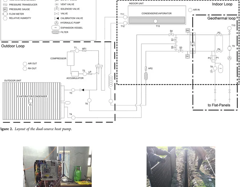
A commercial air-to-air heat pump with rotary inverter compressor and a variable speed indoor unit (2.5 kW, R410a) has been modified to couple a geothermal closed loop via a plate heat exchanger, by modifying the refrigerant piping to bypass the fin and tube air heat exchanger (Figures2and3). In Figure 2, the layout of the built-in copper piping is shown, as redesigned and stretched to allow a new configuration of heat
room
Figure 1. TekneHub lab and testing facilities.
pump system able to divert the refrigerant by means of solenoid valves between the two exchangers, according to the signals provided by the PLC. Therefore, DSHP can operate in air mode (fin & tube air heat exchanger), ground mode (ground heat exchanger), otherwise mix mode by mixing previous solutions as well. Owing to a longer path from the plate heat exchanger
to the compressor in comparison with fin and tube air exchan-ger, a calibration valve was added at the inlet of air heat exchanger to balance the pressure drops, as calibrated in differ-ent working conditions.
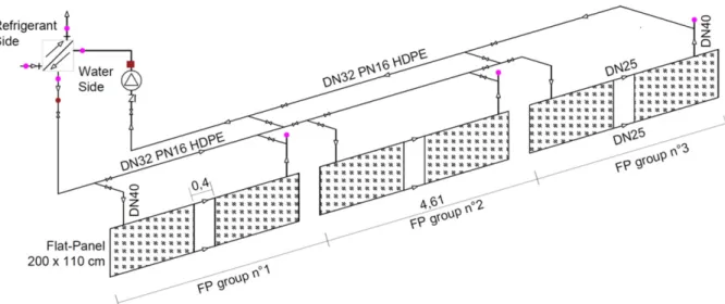
The geothermal closed loop is made up of three pairs of Flat-Panels (FPs) [23], each one 2.0 m long, 1.1 m high and
Figure 2. Layout of the dual-source heat pump.
Figure 3. Air-to-air heat pump, as modified. Figure 4. Flat-Panels and trench.
with an internal cavity 0.017 m wide, making a hollow volume of 30 l. As detailed in Figures4–6, the FPs have been edgeways buried in a trench 2.5 m deep and 0.4 m wide (on average), backfilled with washed sand. A gravel layer with a dedicated irrigation system has been laid at the FP top to soak the trench on demand and improve soil thermal performance. For cover-ing, it has been used soil originated from digging. The sur-rounding soil is plastic clay, and the piezometric level of the groundwater only reaches the FP bottom. The thermo-physical ground properties are listed in Table1, as characterized at the Istanbul Technical University.
The main hydraulic loop depicted in Figure 5 is composed by insulated DN32 HDPE as main collector, a hydraulic pump, and an expansion vessel; four valve groups allow to partialize the piping, so that every pair of FPs can work alone or in series mode, on demand. Finally, a plate heat exchanger installed in the experimental room performs the heat transfer between brine and refrigerant, in parallel or counter flow according to specific valves state. To exploit the system up to −15°C and avoid icing of the geothermal working fluid caused by the tem-perature drop at the plate heat exchanger, 30% of polypropyl-ene glycol was added to the working fluid.
2.2 Automation system
The DSHP automation is managed by means of a program-mable logic controller (PLC) which allows to switch between the two sources under specific conditions. At the moment, three different operating modes are implemented in the control algorithm:
− Automatic: air, ground, or mix modes are automatically con-trolled by the PLC which refers to parameters set by the user (Table2);
− Manual: manual selection of a source mode operated by the user;
− Testing: debug mode for checking the state machine.
The PLC reads continuously data from several sensors (Table 3) and drives four solenoid valves to modify the piping path according to its control algorithm. It is also equipped with a Modbus unit, used to establish a control net with some devices (energy metres, external temperature and humidity
Figure 5. Geothermal closed loop.
Figure 6. Cross section of the trench.
unit, hydraulic pump) and a web server. This latter has been used to implement a web human machine interface (HMI) which allows the remote changing of several set points that affect the PLC decisions (temperature thresholds, timings, hydraulic pump speed, turning on and off the fan, etc.). Data are saved in ASCII files and are available for further processing.
2.3 Monitoring system
As summarized in Table3 and Figure7, more than 50 sensors split in four different data collecting systems have been installed to control the experimental prototype and to monitor its per-formance (SGM-Lektra multiplex, Thermo Fisher Scientific data logger, Eliwell PLC, Davis weather station). Into the ground (Figure7), a first sensor group is installed in boreholes drilled inside and outside the trench, in order to measure the ground temperature at different depths. Then, a thermal heat flux sensor installed 13 cm away and in front of the central FP pair allows to evaluate the heat flux. A second sensors group
monitors temperatures and pressures of the HVAC system in all relevant piping sections. Furtherly, a third group of sensors is deputed to acquire data via PLC in order to evaluate the brine temperature and flow rate. Moreover, electricity supplied to the DSHP and the circulation pump is monitored by means of two single energy metres. Finally, the ice forming on the external fins of air heat exchanger is detected by means of a leaf-wetness sensor. The ice sensor is able to sense different electrical conductivity of air, water and ice therefore supporting the bypass from air to ground.
3 EXPERIMENTAL RESULTS
The system was turned on in January 2017, but several changes were performed by the team to improve both the DSHP and the monitoring system until mid-winter 2018. Moreover, the set of parameters and the PLC were modified several times to opti-mize the switching, and therefore the energy performance. So
Table 1. Soil thermal properties.
Material Heat conduction (W m−1K) Density (kg m−3) Specific heat (kJ kg−1K) Porosity
Dry sand 2.75 1384 0.9 0.448
Wet sand nd 1832 2.78a 0.448
Dry clay 1.52 1824 1.2 nd
a
Estimated according the porosity.
Table 2. Switching control parameters.
Parameter Description Wintera Summera Unit
Tdual Air temperature for activation of the dual-source kit functionality <5 >35 °C
Twater Water temperature range for ground exploitation −2 30 °C
ΔT Temperature difference between ground and air for switching in ground mode 7 −7 °C
tair Time lapse in air mode before switching 5 5 min
twater Time lapse in ground mode before switching 15 15 min
ICE Defrost control √ – –
a
Default values of the system.
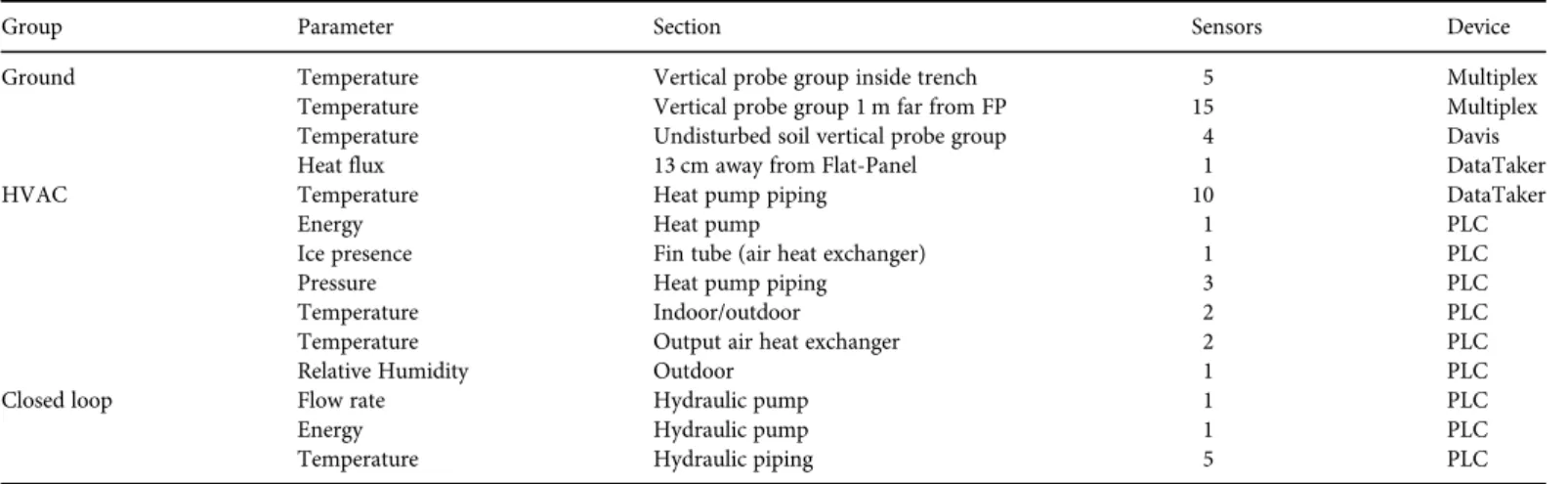
Table 3. Sensors installed.
Group Parameter Section Sensors Device
Ground Temperature Vertical probe group inside trench 5 Multiplex
Temperature Vertical probe group 1 m far from FP 15 Multiplex
Temperature Undisturbed soil vertical probe group 4 Davis
Heat flux 13 cm away from Flat-Panel 1 DataTaker
HVAC Temperature Heat pump piping 10 DataTaker
Energy Heat pump 1 PLC
Ice presence Fin tube (air heat exchanger) 1 PLC
Pressure Heat pump piping 3 PLC
Temperature Indoor/outdoor 2 PLC
Temperature Output air heat exchanger 2 PLC
Relative Humidity Outdoor 1 PLC
Closed loop Flow rate Hydraulic pump 1 PLC
Energy Hydraulic pump 1 PLC
Temperature Hydraulic piping 5 PLC
that, even if the results here reported show the behaviour of two winters and one summer time, the performance are prob-ably underestimated because affected by experimental needs and issues (e.g. calibration valve, manual operating, control par-ameter variation, crash of the HP mainboard, etc.), especially for the first winter and summer time.
That said, the framework of the DSHP is summarized in Table4, while in Table5the overall energy performance for the second winter. Low performance are related to the calibration valve installed to equilibrate the pressure drop between air mode and ground mode; as the pressure drop accounted around 1 bar, at the COP values of Table 5 should be added around 0.4, on
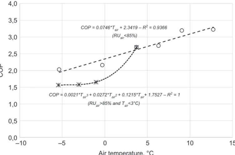
average. To compare the performance between ground mode and air mode at the same time, a statistical relationship was fitted from real data to link the air temperature to the COP. Because of the frosting issue, a different relationship was fitted always from real data when the relative humidity was higher than 85% and the air temperature below 3°C. In those conditions, a cyclic defrosting operation was carried out by the HP, with a frequency related to the thermal power. The two relationships are reported in Figure8; according to those, the COP for air operation at the same time of the ground mode (Air*) is reported in Table 5. With regards of the previous approximations, the difference between the two COP is 0.31, that represent a better performance but not so relevant. The factor load of the HP is around 0.28, therefore oversized for this application. Indeed, the inverter was often not able to equilibrate the system to the energy require-ment, and therefore the HP turned off.
In Figure9, the overall behaviour in terms of time series for air and ground temperatures and heat flux are depicted from February 2017 to May 2018, with evidence of the ground as bet-ter thermal source in comparison with the air. During the sum-mer season, several peaks of heat transfer around 60 W m–2 occurred in ground both with six and two FPs, equivalent to 132 W every metre of trench. The maximum temperatures are achieved in using two FPs; 32°C at the sensor 5002 (0.17 m far from the FP) and 22°C at sensor 1002 (1.0 m far from the FP), both 1.8 m deep in the ground, therefore in front at the mid-panel. At the bottom of the panels (2.5 m deep), the previous locations (0.17 and 1.0 m far from the panel) achieved 25°C and 20°C, respectively for sensor 5001 and 1001, but with a more evident time shift. The maximum temperature of the undisturbed soil at 1.8 m deep was 19°C, therefore only one Celsius degree than the sensor 1001, but their difference achieved more than 2.5 K in July. According the trend in October, the overheating carried out during the summer season was quickly removed by the overall trend of the ground tem-perature, as controlled by the environmental climate. In winter time, when the PLC was more advanced in terms of control
Figure 7. Ground monitoring system.
Table 4. Operating framework.
1st period 2st period Winter Summer Winter Start time 13/2/2017 15/5/2017 1/11/2017 End time 15/5/2017 10/10/2017 30/4/2018 Flooded trench condition 100% 30% 100% Average brine flow rate, (m3h−1) 0.417 0.417 0.417
Indoor air flow rate (m3h−1) 400 400 400
Setpoint (°C) 20–23 24–26 20–23
Table 5. Energy performance for the second winter.
Air Ground Air* DSHP
Global thermal energy (kWh) 2154 757 757 3070
Hours (h) 1868 644 644 2648
COP 2.55 2.49 2.18 2.53
COP = 0.0746*Tair + 2.3419 – R
2 = 0.9366
(RUair<85%)
COP = 0.0021*Tair3 + 0.0272*Tair2 + 0.1215*Tair+ 1.7527 – R
2
= 1
(RUair>85% and Tair<3°C)
0,0 0,5 1,0 1,5 2,0 2,5 3,0 3,5 4,0 –10 –5 0 5 10 15 COP Air temperature, °C
Figure 8. COP in air source mode with and without frosting conditions.
rules, the switching occurred with a more evident continuity in buffering hard air temperatures, especially in mid-January and late February. The maximum heat flux achieved in winter was around 40 W m−2, equivalent to 88 W for every metre of trench. The overall heat extracted from the soil in 6 months was around 757 kWh, whose 176 kWh in 2 months (February
and March) with only 2 FPs. Therefore, the DSHP extracted 581 kWh in 4 months using 6 FPs, equivalent to 0.404 kWh d−1 for every metre of trench, whereas 176 kWh in 2 months using 2 FPs, equivalent to 0.758 kWh d−1.
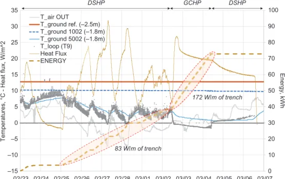
In Figure 10, a hard period occurred in Northern Italy is detailed, once the so-called Burian wind from Russia reached
–120 –90 –60 –30 0 30 60 –10 0 10 20 30 40 50 17/02 17/03 17/04 17/05 17/06 17/07 17/08 17/09 17/10 17/11 17/12 18/01 18/02 18/03 18/04 18/05
Heat flux, W/m^2 - Compressor inlet temperature, °C
Soil temperatures, °C T_air OUT T_ground ref. (–2.5m) T_ground 1002 (–1.8m) T_ground 1001 (–2.5m) T_ground 5002 (–1.8m) T_ground 5001 (–2.5m) T_in compressor (T9) Heat flux 2 FPs 2 FPs 6 FPs 6 FPs 6 FPs
Figure 9. DSHP overall behaviour.
0 10 20 30 40 50 60 70 80 90 100 –15 –10 –5 0 5 10 15 20 25 30 35 02/23 02/24 02/25 02/26 02/27 02/28 03/01 03/02 03/03 03/04 03/05 03/06 03/07 Energy, kWh
Temperatures, °C - Heat flux, W/m^2
T_air OUT T_ground ref. (–2.5m) T_ground 1002 (–1.8m) T_ground 5002 (–1.8m) T_loop (T9) Heat Flux ENERGY 172 W/m of trench 83 W/m of trench DSHP GCHP DSHP
Figure 10. DSHP detailed behaviour in icing condition of the trench.
the Southern Europe during the winter 2017/18. At that moment, the closed loop operated with two FPs; for the first 7.5 days the DSHP was set in automatic mode with a ΔT for switching set to 5 K, then the DSHP was set to operate only with ground for 2 days to monitor the trench icing phenom-enon, and finally the system returned in automatic mode. In automatic mode, the permanence in ground mode was set at least for 15’, whereas in air mode for 5’.
From 25 February to 3 March, the overall heat transfer car-ried out from the FPs accounts around 34 kWh, whereas the average heat flux monitored by the sensor installed on the wall trench is 15.3 W m−2. A quick check of the data can be carried out by accounting the energy balance occurred in those 5.5 days as follows:
ρ
= Δ + Δ ( )
Q Sq t cV T 1
whereΔt, period considered (5.5 × 24 h); Q, energy exchanged by the two Flat-Panels with the ground during the period con-sidered (kWh); q, average heat flux monitored by the sensor installed on the wall trench 0.2 m away from the FP, during the period considered (0.0153 kW m−2); S, surface where occurs the heat flux q, accountable for simplicity at the FPs surface (8.8 m2); V, volume of the trench occupied by the two FPs and filled with soaked sand (2.34 m3); ρ, density of the soaked sand (1832 kg m−3); ΔT, final cooling down of the soaked sand (4.2 K) and c, specific heat of the soaked sand (2.78 kJ kg−1K−1). The first term at the right of the previous equation accounts around 17.8 kWh, and the second one around 13.9 kWh, that summarize 31.7 kWh; according the approximations applied (especially for the trench wide, not so regular in digging), the check should be considered as verified, on average. That said, Figure 10shows how the DSHP smooths the very low air tem-peratures in the first period, never working with temtem-peratures below zero. But more interesting is the speed in partially
recovering higher temperatures, when the sun rises and the air temperature grows. The possibility to switch with another heat source (air) allows to replace for a relevant share the energy exploited during the night. Furtherly notable is icing period, once the operating was manually switched in ground mode to overload the closed loop. The continuity of this thermal exploit-ation causes the quick drop down of the temperature that leads the phase change of the soaked sand, being below zero. Finally, it should be also observed that around 33 kWh were exchanged during this period of 2 days, equivalent to a heat flux occurred at the two working FP2 of 172 W per metre of trench, or similarly equal to 156 W per square metre of Flat-Panel, accounting for a single side. Similar performance is not common with other type of ground heat exchangers, neither vertical nor horizontal.
Finally, Figure11reports a single day (19/12/2017), in which air and ground modes are well depicted. Until 9:00 AM, the air mode operated with an air temperature from −3°C to −5°C. Due to an high relative humidity, frosting conditions needed 5 cycle inversions of the HP, every time affected by an indoor temperature decrease up to 19–20°C. During the night time, the high and low pressure were around 21 and 3 bar, respect-ively, and the power 820 W. Always in air mode, during the day time from 9:00 AM to 4:30 PM the air temperature increased and the low pressure at the evaporator too up to 5 bar. Two large increments were a consequence of a manual switching in ground mode; the temporary high temperature of the thermal source (+7°C) allowed a further increment of the low pressure up to 6 bar. Other five increments of few minutes occurred in mix mode, as consequence of a PLC debug operation. Then, from 4:30 PM, the ground mode was continuously operating. On average, the low pressure remained steadily around 6 bar, the high one 22 bar and the power 550 W. No icing problem had to manage and the indoor temperature remained around 25°C, with evidence of a higher heating performance.
0 300 600 900 1200 –15 –10 –5 0 5 10 15 20 25 30 35 40 45 0:00 3:00 6:00 9:00 12:00 15:00 18:00 21:00 0:00 Power, W
Pressure, bar - Temperature, °C
T_air OUT T_air IN T_evaporator (T3/T6) T_loop (T9)
T_condenser (T11) High pressure (HP1) Low pressure (LP) HP_power
MIX MODE TESTING
Figure 11. DSHP behaviour during the day 2017/12/19.
4 CONCLUSION
A common air-to-air heat pump has been modified by coupling via a plate heat exchanger a geothermal closed loop, composed by an innovative horizontal ground heat exchanger (Flat-Panel). The goal has been to perform a dual-source heat pump (DSHP), able to switch between air and ground according the more profitable temperature. The DSHP can represent a smart solution to overcome the disadvantages of a single-source heat pump, because offers the most suitable thermal source, reduces the frosting issue during winter (air-source heat pumps) and allows to reduce drastically the length of the ground heat exchangers (ground coupled heat pumps), which are the most relevant installation cost of a geothermal heat pump.
The final prototype operated for the whole winter time 2017–18, for testing the behaviour and to support parametric rules to be implemented in the control system (PLC), according the length of the geothermal closed loop. The temperature dif-ference between air and ground is the main parameter that con-trols the closed loop length; the higher the difference, the shorter the length and therefore the lower the installation cost, but also the overall energy saving. Another important param-eter is the threshold temperature for activating the dual func-tionality, because anticipates or retards the ground depletion; the higher the threshold, the quicker the depletion of the ground.
Even if the DSHP prototype has shown better performance than the original air-to-air heat pump, the extra-cost of the revamping kit only partially justifies the starting investment, although increases the indoor comfort when hard weather con-ditions occur. If the starting point is a ground source heat pump, the DSHP allows a shorter ground heat exchanger and therefore lower installation costs.
ACKNOWLEDGEMENTS
Special thanks to Dr A. Alper Aydın (Istanbul Technical University, Turkey) for his support in assessing the ground thermo-physical properties. The research has received funding in the frame of the European Regional Development Fund (Regional funds of Emilia Romagna 2014–2020, Italy) under grant agreement no. CUP D92I16000050009 (HEGOS project).
REFERENCES
[1] EC. Communication from the Commission to the European Parliament, the Council, the European Economic and Social Committee and the Committee of the Regions – An EU Strategy on Heating and Cooling, SWD 24 final. 2016. https://ec.europa.eu/transparency/regdoc/rep/1/2016/ EN/1-2016-51-EN-F1-1.PDF
[2] Wang F, Liang C, Zhang X. Research of anti-frosting technology in refrigeration and air conditioning fields: a review. Renew Sust Energy Rev 2018;81:707–22.
[3] Jang YJ, Bae HB, Lee JS, et al. Continuous heating of an air-source heat pump during defrosting and improvement of energy efficiency. Appl Energy 2013;110:9–16.
[4] Dongellini M, Naldia C, Morini GL. Annual performances of reversible air source heat pumps for space conditioning. Energy Procedia 2015;78: 1123–8.
[5] Vocale P, Morini GL, Spiga M. Influence of outdoor air conditions on the air source heat pumps performance. Energy Procedia 2014;45:653–62. [6] Urchueguía JF, Zacarès M, Corberàn JM, et al. Comparison between the
energy performance of a ground coupled water to water heat pump system and an air to water heat pump system for heating and cooling in typical conditions of the European Mediterranean coast. Energy Convers Manag 2008;49:2917–23.
[7] Aresti L, Christodoulides P, Florides G. A review of the design aspects of ground heat exchangers. Renew Sust Energy Rev 2018;92:757–73.
[8] Habibi M, Hakkaki-Fard A. Evaluation and improvement of the thermal performance of different types of horizontal ground heat exchangers based on techno-economic analysis. Energy Convers Manag 2018;171:1177–92. [9] Corberán JM, Cazorla-Marín A, Marchante-Avellaneda J, et al. Dual source
heat pump, a high efficiency and cost-effective alternative for heating, cool-ing and DHW production. Int J Low Carbon Technol 2018;13:161–76. [10] Yang WB, Zhu JL, Chen ZQ, Investigation on the influences of
under-ground thermal imbalance ratio on soil temperature variation of under-ground coupled heat pump, 7th International Symposium on Heating, Ventilating and Air Conditioning – Proceedings of ISHVAC 2011, 4, 2011. pp. 1334–1340.
[11] Yang W, Chen Y, Shi M, et al. Numerical investigation on the underground thermal imbalance of ground-coupled heat pump operated in cooling-dominated district. Appl Therm Eng 2013;58:626–37.
[12] Wang E, Zhang F, Zhang Y, et al. Influence investigation of thermal load imbalance on geothermal heat exchanger. Procedia Eng 2017;205:3846–51. [13] Allaerts K, Coomans M, Salenbien R. Hybrid ground-source heat pump
sys-tem with active air source generation. Energy Convers Manag 2015;90:230–7. [14] Bortoloni M, Bottarelli M, Su Y. A study on the effect of ground surface boundary conditions in modelling shallow ground heat exchangers. Appl Therm Eng 2017;111:1371–7.
[15] Fujii H, Yamasaki S, Maehara T, et al. Numerical simulation and sensitivity study of double-layer slinky-coil horizontal ground heat exchangers. Geothermics 2013;47:61–8.
[16] Somogyi V, Sebestyén V, Nagy G. Scientific achievements and regulation of shallow geothermal systems in six European countries– a review. Renew Sust Energ Rev 2017;68:934–52.
[17] Bottarelli M. Numerical analysis of heat transfer induced by a horizontal ground heat exchangers in an heterogeneous soil. Int J Heat Technol 2010; 28:141–6.
[18] Gan G. Dynamic thermal modelling of horizontal ground-source heat pumps. Int J Low Carbon Technol 2013;8:95–105.
[19] Bottarelli M, Gabrielli L. Financial and economic analysis for ground-coupled heat pump using shallow ground heat exchangers. Sustain Cities Soc 2016;20:71–80.
[20] Bottarelli M, Zhang L, Bortoloni M, et al. Energy performance of a dual air and ground-source heat pump coupled with a Flat-Panel ground heat exchanger. Bulg Chem Commun 2016;48:64–70.
[21] Cannistraro M, Mainardi E, Bottarelli M. Testing a dual-source heat pump. Math Model Eng Probl 2018;5:205–10.
[22] Grossi I, Dongellini M, Piazzi A, et al. Dynamic modelling and energy per-formance analysis of an innovative dual-source heat pump system. Appl Therm Eng 2018;142:745–59.
[23] Geothermal System, EP 2 418 439 A2, European patent Application n.11177528.4, Università degli Studi di Ferrara, M. Bottarelli, (2012).