Abstract— Lower-limb loss is a dramatic event affecting quality of life and often reducing independence. Moreover, lower-limb losses are foreseen to double by 2050. An active Knee-Ankle Foot Orthosis (KAFO) could represent an assistive tool for lower-limb amputees to reduce the extra-torque typically generated by the muscles of the sound limb due to compensatory strategies adopted to deal with a passive prosthesis during gait. Within the CYBERLEGs project, a novel active KAFO was designed to assist the knee and the ankle joints during ground level walking. In this paper the mechatronic design of the device is presented for the first time. Moreover, the paper presents the control strategy developed to provide knee and ankle assistance and the experimental results with two volunteers with lower-limb amputation. The KAFO was shown to: (i) fulfill all the design functional requirements to comply with range of motion, torque, speed and power; and (ii) provide assistive torque in the most demanding phases of the gait cycle. Tests with end-users showed that the assistive action resulted in physiological profiles of the knee and ankle angles and torques, showing a first proof of feasibility for the presented system. Both subjects reported comfortable interaction with the exoskeleton, but results on the metabolic consumption were not conclusive. This feasibility study will be extended in the future with an optimized controller to further explore the effectiveness of the system.
I. MOTIVATIONS
Worldwide, the main causes of lower-limb amputation are vascular disorders, such as diabetes and peripheral arterial diseases and the incidence of those is foreseen to grow in the next years, leading to twice as many amputations in 2050 compared to 2005. By then, more than 2 million people are expected to undergo a lower-limb amputation only in the USA [1]. Lower-limb loss is a dramatic event affecting health and quality of life, in many cases reducing independence and causing psychological distress. Indeed, typically dysvascular amputees adopt a slower gait speed of that of non-amputees (about 40%) and expend 2.5 times the energy that non-amputees expend. Consequently, physical
This work was supported in part by the EU within the CYBERLEGs project (FP7-ICT-2011-2-1, Grant Agreement #287894) and the CYBERLEGs Plus Plus project (H2020-ICT-2016-1 Grant Agreement #731931). CB. Sanz Morère, M.Fantozzi, A.Parri, F. Giovacchini, A.Baldoni, S. Crea and N. Vitiello are with TheBioRobotics Institute, Scuola Superiore Sant’Anna, Pontedera (PI), Italy. N. Vitiello is also with the Don Carlo Gnocchi Foundation, Firenze, 50143, Italy. Corresponding
author: Clara Beatriz Sanz-Morère,
activity is reduced in daily life which in turn, further worsens the subject clinical conditions. Indeed, it has been showed that for dysvascular amputees, there is an incidence of 15% for contralateral limb amputation [2] and up to 74% of amputees face death within 5 years [3]. Currently, amputees mostly use passive prostheses, which may include passive components, or semi-active prostheses, including microprocessor-controlled knees or ankles. However, due to the missing power source, passive and semi-active prostheses exert lower power than healthy legs during walking, and the sound limb has to compensate for it: the sound limb might exert up to 60 % more extension torque to the knee during the stance phase of ground level walking [4]. This extra-torque requirement can be a source of increased metabolic effort, quicker tiredness and reduced mobility. In this framework, the global goal of the CYBERLEGs project (www.cyberlegs.eu) was to develop a modular robotic ortho-prosthesis for lower-limb functional replacement and assistance. One of the main modules was constituted of a wearable active knee-ankle-foot orthosis (KAFO) for assisting the sound limb.
II. STATE OF THE ART
KAFOs are used to provide stability and assistance to the knee and the ankle during gait. They can be classified into three main categories, i.e. passive devices, stance-control (SC)-KAFOs and active KAFOs. Passive KAFOs provide support during walking by blocking the knee joint at a fixed angle. While the stability is always ensured, the lack of knee flexion leads to compensation strategies, such as hip hiking and circumduction. SC-KAFOs were born to overcome the limitations of passive devices, integrating a spring-loaded knee-blocking mechanism to support the weight acceptance phase and allow the free knee flexion during swing. Active KAFOs integrate actuators with the goal of applying additional power to reproduce physiological gait patterns [5]. Knee assistance generally concerns the early stance phase, where extension torque is delivered by means of compression springs or series-elastic actuators (SEAs) [6]. Among the few examples of active KAFOs presented in literature, only two are able to provide assistance in both flexion and extension phases of the knee [7, 8].
While many active ankle exoskeletons have been designed, the ankle joint of state-of-the-art powered KAFOs is generally passive (either blocked in a dorsiflexed configuration or spring loaded). Active ankle orthoses are designed to provide power during the push-off phase, where
A bioinspired control strategy for the CYBERLEGs
knee-ankle-foot orthosis: feasibility study with lower-limb amputees
Clara Beatriz Sanz-Morère, Matteo Fantozzi, Andrea Parri, Francesco Giovacchini, Andrea
Baldoni, Simona Crea, Member IEEE, Nicola Vitiello, Member IEEE
the highest energy expenditure is required. Several active ankle orthoses use SEAs in order to release active energy right after contralateral heel strike, and some have been already validated to assist, for example, drop-foot gait [9, 10]. Most of these systems, however, are based on pneumatic muscles or use EMG control strategies, which by design limit their portability.
In this scenario, the challenge lies in designing a portable active knee and ankle orthosis, able to provide effective assistance in stance and swing phases. Despite the existence of several examples of knee or ankle SEA-based exoskeletons in the state of the art [6, 9], the only example of KAFO with actuated knee and ankle is the one presented by Sawicki and Ferris [7]. Despite more versatile than most of the KAFOs in literature, the system requires an external air source to power the actuators, which makes the system bulky to be usable in activities of daily life. This paper presents the design of the CYBERLEGs active KAFO and its preliminary experimental validation with lower-limb amputees. The system advances the state of the art, being able to provide torque assistance during the entire gait cycle to the knee and the ankle in the sagittal plane. Integrated sensors are used to compute the gait phase in real time and control the knee and ankle assistive action accordingly, in an intuitive and reliable way.
III. DESIGN REQUIREMENTS
In this section, human knee and ankle physiological kinetics and kinematics are described and the main design requirements of the CYBERLEGs KAFO are introduced.
A. Gait biomechanics
The knee joint has different functions during gait. During early stance, the knee joint supports the person decelerating the body mass in order to accomplish the so-called weight acceptance, by generating a high extension torque of 0.42 N∙m/kg. Then, a second peak of extension torque of 0.22 N∙m/kg occurs in late stance, around 50 % of the gait cycle. That torque increases the stiffness of the joint during the push-off phase to ensure enough inertia to passively flex the knee joint as in a free pendulum moment in early swing [11,
12]. Regarding the ankle joint, the torque increases quasi-linearly during the stance phase until reaching a maximum plantarflexor peak of 1.30 N∙m/kg right before push-off, with the goal of propelling the limb during the consequent swing phase [12].
The ranges of motion (RoM) of knee and ankle during walking vary respectively from 0° to -65° and from -15° to 20°, positive values corresponding to extension and plantarflexion. Similarly, the knee and ankle rotational speeds vary along the gait cycle, reaching a maximum absolute value of around 58.4 r/min at the knee during the final swing phase, and around 43.0 r/min at the ankle during the swing phase to provide ground clearance [12].
B. KAFO requirements
The CYBERLGEs KAFO has been designed to provide a portion of the biological torque at the knee and ankle joints. The torque requirement was set to 1/3 of the biological torque for both knee and ankle, which was considered as an adequate trade-off between the need of providing high active assistance while achieving acceptable weight as a portable device. Moreover, the KAFO was designed to provide similar range of motion and joint velocity of the human joints, in order to allow the user to perform natural movements without restrictions. Figure 1 presents physiological joint angles and torques from [12], adapted to a 80 kg subject, and a graphical overview of the functional design requirements fulfilled by the KAFO.
IV. THE CYBERLEGS KAFO
This section describes the mechanical design, electronics and control of the CYBERLEGs KAFO. Notably, the system was designed to be used in combination with a bilateral hip exoskeleton for hip flexion-extension assistance (namely an Active Pelvis Orthosis, APO). The APO has been presented and validated in previous studies; more details can be found in [13]. The two devices share the control electronics and power supply.
A. Mechanical structure and actuation units
The CYBERLEGs KAFO is an active device with two active degrees of freedom (DoFs) and provides assistance for knee flexion/extension movements as well as ankle plantar/dorsiflexion.
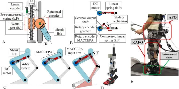
The knee actuation is performed through a SEA architecture: a 90W brushless linear DC motor (EC-4pole 22, Maxon Motor®, Sachseln, Switzerland) drives a wormgear mounted on a splined shaft between two pre-compressed linear springs as shown in Figure 2A. The knee actuator is approximatively irreversible and allows a maximum elastic torque value of 42 N∙m of passive support. The SEA exerts up to 30 N∙m of active torque when joint rotation and torque occur in the same direction and 38 N∙m when opposite. The joint torque 𝜏𝐾 can be derived from (1):
𝜏𝐾= 2𝑘𝑅𝑃∆𝑥, (1)
where k is the stiffness of the single linear spring (41.4 N/mm),
𝑅
𝑃 is the primitive radius of the wormwheel (34 mm), and∆𝑥
is the linear translation of the wormgear measured with a 26-bit absolute linear encoder Figure 1 Overview on the functional requirements of the CLsKAFO for knee (first row) and ankle (second row) regarding joint angles and torques (first and second column). Dashed lines represent the adapted physiological data [12] and solid lines the target values. Light blue areas represent the covered angle and torque output of the final device.
(RESOLUTE™, scale: RSLA A9765-0060, read head: RL26BAS001C50A, Renishaw®, Gloucestershire, England). The values were chosen to obtain 1/3 of the equivalent torsional stiffness of a healthy knee (calculated from [12]), which was finally equal to 95.7 N∙m/rad. The sensor for knee joint angle measurement is a 17-bit absolute Rotary Electric Encoder™ (DS-25 Netzer Precision Motion Sensors Ltd, Misgav, Israel). The range of motion of the knee orthosis is [-150°; 3°], with positive angles referring to extension. Mechanical stops at 0º and 150º avoid hyperextension and hyperflexion.
The ankle actuation system relies on a sliding bar Mechanically Adjustable Compliance and Controllable Equilibrium Position Actuator – namely MACCEPA – powered by a 70 W brushless DC motor (EC-45, Maxon Motor®, Sachseln, Switzerland) as shown in Figure 2B. The DC motor drives the gearbox output shaft by rotating it in an angle α which results in a compression of the linear spring. The torque created by the compression of the spring drives the MACCEPA input arm which is displaced of an angle β with respect to its initial position. Stiffness and pre-compression of the spring were selected to minimize the work of the system over a gait cycle while maintaining the power peak sufficiently close to the minimum, as well as to minimize the energy consumption. The spring was chosen with stiffness equal to 72.2 kN/m and an initial displacement of 12 mm. Moreover, the MACCEPA is connected in series to a 4-bar linkage as schematized in Figure 2C. The ankle angle is extrapolated from the 4-bar linkage kinematic equation and the MACCEPA input arm angle measured using a 17-bit absolute Rotary Electric Encoder™ (DS-25, Netzer Precision Motion Sensors Ltd, Misgav, Israel). A 17-bit absolute Rotary Electric Encoder™ (DS-37, Netzer Precision Motion Sensors Ltd, Misgav, Israel) reads the gearbox output shaft angular position. The relative angle
between the two encoders is a direct measure of the MACCEPA displacement angle α. Torque at the ankle 𝑇𝐴 is obtained by multiplying the MACCEPA torque 𝑇𝑀 [14] by the angle-dependent value of the reduction ratio 𝑅𝑅 produced by the 4-bar mechanism as in (2):
𝑇𝐴(𝛼, 𝛽) = 𝑇𝑀(𝛼) ∙ 𝑅𝑅(𝛽). (2) The actuator is capable of exerting a peak torque of 43.5 N·m, which is about 1/3 of the human ankle torque and the ankle actuator is fast enough (maximum speed is 4.5 rad/s, equal to 43 r/min) to provide ground clearance during the swing phase. The obtained range of motion is [-29°; 52º], positive values corresponding to plantarflexion. A CAD model of the KAFO is provided in Figure 2D.
The KAFO control system runs on a real-time processing unit implemented in a reconfigurable input/output board sbRIO-9632, endowed with a 400 MHz processor with a NI real-time operating system and a field programmable gate array (FPGA)
.
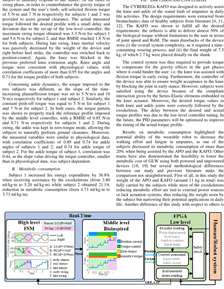
The system is based on a three-layer hierarchical architecture that comprises high, middle and low-level controllers.High-level control: The KAFO high-level control classifies the locomotion mode and segments the gait cycle into discrete phases. It receives as inputs the vertical Ground Reaction Force (vGRF) and Center of Pressure (CoP) measured by two pressure-sensitive insoles [15, 16]. Based on the vGRF and CoP, a finite-state machine (FSM) can classify in real time two locomotion modes (i.e. quite standing, QS, and ground level walking, GLW) and the two main phases of GLW, i.e. the stance and swing phases. In particular, the QS mode is characterized by both left and right vGRF over specific thresholds, set depending on the user’s body weight. When the vGRF of one side goes below a certain threshold, the GLW mode is detected. A
threshold-Figure 2: A) Diagram of the knee actuation unit. B) Diagram of the MACCEPA working system in resting position (up) and loaded by the motor (down). C) Diagram of the ankle actuation unit combining the MACCEPA with a 4-bar system. D) CAD model of the KAFO. E) Experimental set-up.
based algorithm on the left and right CoP measurements allows to segment the gait cycle into five sub-phases (Figure 3): early-, mid- and late- stance, and early- and late- swing. CoP thresholds modulating the transitions between early and mid-stance and between early and late swing are subject-dependent.
Middle-level layer: The middle layer aims at computing the desired assistive strategy for each actuation unit based on the identified task and segmented phase. At the beginning of the stance phase the knee is controlled in position mode, i.e. the knee angle is held at the fully extended position reached at the end of the swing phase (notably, the springs of the knee joint make the system compliant for shock absorption and weight acceptance). In the late stance, the knee controller switches to torque control. In swing, a gravity compensation algorithm provides a subject-dependent flexion torque to neutralize the weight of the device and of the user’s limb. In the late swing phase, the position of the knee is again fixed to safely face the upcoming weight acceptance phase. The ankle is controlled in torque mode throughout the whole gait cycle. During stance, the assistive strategy provides a time-linear plantarflexion torque to contribute to sustain the body weight. At late-stance phase, a constant subject-specific plantarflexion torque is set. During swing, a zero-torque mode allows for free dorsiflexion to ensure ground clearance.
Low-level layer: The low-level controller implements two independent torque or position closed-loop controllers for each actuation unit, with the goal of tracking the desired control reference received as input from the middle level layer. The closed-loop torque and position control architectures of the knee and ankle are proportional– integral–derivative (PID) regulators, operating on the error between the desired torque or position and the measured variable, and return an electrical current provided to the motor.
V. EXPERIMENTALTESTS A. Experimental set-up and protocol
The set-up used in the experiments is presented in Figure 2E, where participants were requested to wear the APO, KAFO and instrumented shoes and walk assisted by the device. The metabolic consumption of subjects was estimated based on the measurement of the oxygen uptake and carbon dioxide release through an indirect portable calorimeter, i.e. Oxycon Mobile (©Carefusion, St. Albans, UK). The duration of the trials was set to the minimum time to reach the steady state measurement, i.e. 4 minutes.
The experiments consisted in three walking sessions. First, a familiarization session let participants familiarize with the system and fine tune the high and middle-level controllers of the KAFO. Then, two testing sessions consisted of walking on the treadmill at self-selected speed for 4 minutes (namely 4-minutes walking trials, 4mWT). The first testing session was an assisted walking session performed with the APO and KAFO, whereas the second session (namely the baseline trial) was performed without wearing the exoskeletons. Before the two testing sessions, subjects were requested to stand for 1 minute to measure the
metabolic consumption in resting position; between sessions, a break was included to allow resting and avoid fatigue effects.
Two male subjects with right-leg amputation volunteered to participate to the experiment: subject 1 was 68 years old and subject 2 was 33 years old. Both subjects had sufficient mobility to complete the trials.
B. Data analysis
Several kinematics and kinetics variables were measured and stored by the APO and KAFO, for offline analysis. The measured knee and ankle angles and torques were saved, synchronously with vGRF, CoP and the discrete gait phases computed online. In offline data processing, joint angles and torques were segmented in strides based on the online computed discrete gait phase; data of each stride were then resampled between 0 % and 100 % of the gait cycle. From the collected variables the average profiles of the angles and torques were calculated, along with the standard deviations.
The reliability of the controller was verified by computing the Root Mean Square Error (RMSE) between the desired torque profile and the torque measured in the phases of the gait cycle controlled in torque mode, i.e. late stance and early swing for the knee and the complete stride for the ankle. Then, angles and torque values were compared to the physiological ones from [12] by calculating the correlation coefficient in the same phases of the gait cycle. For the knee, the torque considered was net, i.e. the sum of the torques exerted by the exoskeleton and by gravity.
To compute the cost of walking, the oxygen uptake volume VO2 and dioxide production VCO2 measured by the Oxycon Mobile were filtered with a running average filter over a span of five samples. Metabolic consumption was computed by applying the Brockway equation [17] to the mean VO2 and VCO2 of the last 2 minutes of the 4mWT, when a VO2 steady state was reached; the consumption was computed also from the data of the QS condition at the start of the trial. The final metabolic consumption was obtained as the difference between the Brockway value during GLW and the one during QS, normalized to body weight and walking speed.
VI. RESULTS A. Joint kinematics and dynamics
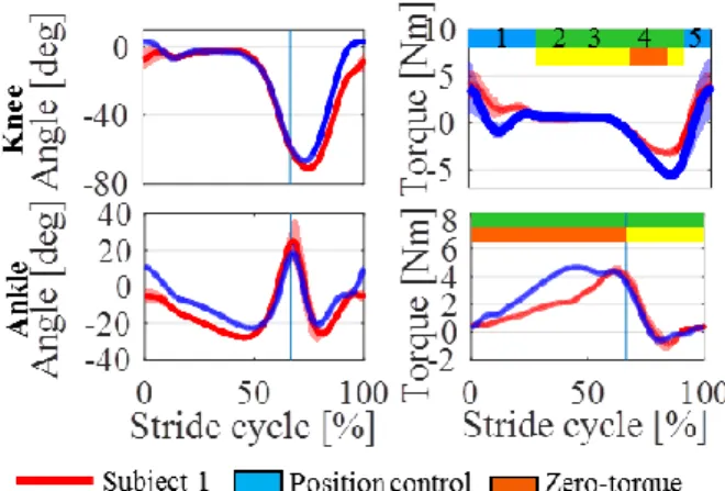
Knee and ankle kinematics and dynamics of both participants are presented in Figure 4. Subjects show similar RoM in the knee, also consistent with the physiological data shown in Figure 1. In early-stance, the knee joint was position-controlled, compelling the knee angle to remain in the last measured position before heel strike, respectively -1° and -2° for Subject 1 and 2. The KAFO knee motor was kept blocked until 28% of gait cycle (i.e. till the end of the weight support sub-phase), which was translated into a stable knee angle for both subjects. Moreover, the linear springs of the SEA allowed a compliant damping in the weight acceptance phase. Both subjects agreed on the comfort of this interaction. At the end of the weight acceptance phase the knee controller was switched from position to torque control (green rectangle Figure 4). A desired zero-torque reference was commanded to the low-level controller, allowing the
subject to naturally respond to late stance. At the onset of swing phase, in order to counterbalance the gravity torque of the system and the user’s limb, self-selected flexion torque of 5 N⋅m and 7 N⋅m respectively for subjects 1 and 2 was provided to assist ground clearance. The actual measured torque followed the desired profile with a small delay and deviation due to the set-up of the low-level controller: the maximum swing torque obtained was 3.3 N∙m for subject 1 and 5.6 N∙m for subject 2, and thus RMSE reached 1.8 N∙m for both subjects. During late swing, knee inertial velocity was passively decreased by the weight of the device and right before heel strike, the controller was switched back to position-control. Again, the knee was blocked in the previous preferred knee extension angle. Knee angle and torque were consistent with physiological values, with correlation coefficients of more than 0.95 for the angles and 0.71 for the torque profiles of both subjects.
Concerning ankle dynamics, the torque imposed to the two subjects was different, as the slope of the time-increasing plantarflexion torque was set to 5 N∙m/s and 10 N∙m/s respectively for subject 1 and subject 2. Similarly, the constant push-off torque was equal to 5 N∙m for subject 1 and 7 N∙m for subject 2. In both cases, the torque pattern was shown to properly track the reference profile imposed by the middle level controller, with a RMSE of 0.85 N∙m and 0.71 N∙m respectively for subjects 1 and 2. During swing, the ankle was kept in zero-torque mode, allowing the subjects to naturally perform ground clearance. Moreover, the measured variables were similar to physiological data, with correlation coefficients of 0.89 and 0.74 for ankle angles of subjects 1 and 2; and 0.74 for ankle torque of subject 2. For the ankle torque of subject 1, correlation was 0.44, as the slope value driving the torque controller, smaller than in physiological data, was subject-dependent.
B. Metabolic consumption
Subject 1 increased his energy expenditure by 36.8% when receiving assistance by the exoskeletons (from 3.80 ml/kg∙m to 5.20 ml/kg∙m) while subject 2 obtained 21.1% reduction in metabolic consumption (from 4.73 ml/kg∙m to 3.73 ml/kg∙m).
VII. DISCUSSION AND CONCLUSIONS
The CYBERLEGs KAFO was designed to actively assist the knee and ankle of the sound limb of amputees in daily life activities. The design requirements were extracted from biomechanics data of healthy subjects from literature [4, 11, 12]. The KAFO was shown to fulfill all the desired requirements: the orthosis is able to deliver almost 50% of the biological torque without limitations to the user in terms of joint speed and RoM. The main drawbacks of the device were (i) the overall system complexity, as it required a time-consuming wearing process, and (ii) the final weight of 7.5 kg, of which 2.7 kg were placed distally on the shank.
The control system was thus required to provide torque to compensate for the gravity effects in the gait phases where it could hinder the user: i.e. the knee was assisted with flexion torque in early swing. Furthermore, the controller of the device was able to ensure weight acceptance in the knee by blocking the joint in early stance. However, subjects were satisfied using the device because of the compliant interaction given by the Series-Elastic elements embedded in the knee actuator. Moreover, the desired torque values in both knee and ankle joints were correctly followed by the exoskeleton. The delay between the desired and actual torque profiles was due to the low-level controller tuning. In the future, the PID parameters will be optimized to improve the timing of the actual torque profile.
Results on metabolic consumption highlighted the potential ability of the wearable robot to decrease the walking effort and fatigue in amputees, as one of the subjects decreased its metabolic consumption of more than 20% when being assisted by the APO and the KAFO. Other teams have also demonstrated the feasibility to lower the metabolic cost of GLW using both powered and unpowered devices [18, 19] but several methodological differences between our study and previous literature make the comparison not straightforward. First of all, in this study the weight of the APO and KAFO (around 11 kg in total) was fully carried by the subjects while most of the exoskeletons reducing metabolic effort are tied to external power sources or lack actuation systems, thus reducing the weight worn by the subject but narrowing their potential applications in daily life. Another difference of this study with respect to others is
Figure 3: Diagram of the KAFO control. The high level determines the gait phase through a FSM, the Middle Level computes the desired torque or position and the Low Level sends the command to the motors and reads the encoders and sensorized shoes data.
the lack of proper training prior to data acquisition; in our case a 4-minute familiarization trial was performed whereas previously it was shown that the metabolic cost using an exoskeleton can reduce with training [20]. This was due to the fact that subjects, even if fit and independent, were not capable of walking with the complete system for long periods.
By the way, this work presents the first application of a wearable exoskeleton to amputees, thus no direct comparison can be made between previous literature and the present study. It is notable also that the subject who reduced its consumption received a higher plantarflexor torque than the subject who increased its metabolic effort. Furthermore, the characteristics of both subjects differ, with more than 35 years of age difference as well as more than 5 in the use of the prosthesis. This study will be extended in the future with data from additional subjects to further investigate the relationship with the level of assistance, subject characteristics and metabolic consumption. Moreover, EMG recordings could be of great help to understand the real effect of the assistance in the muscle activations, and motion analysis could aid in the tuning of the middle level assistive parameters as regards amplitude and timing of assistive torque.
REFERENCES
[1] K. Ziegler-Graham, E. J. MacKenzie, P. L. Ephraim, T. G. Travison, and R. Brookmeyer, "Estimating the Prevalence of Limb Loss in the United States: 2005 to 2050," Archives of Physical Medicine and Rehabilitation, vol. 89, no. 3, pp. 422-429, 2008/03/01/ 2008.
[2] A. Johannesson, G.-U. Larsson, N. Ramstrand, A. Turkiewicz, A.-B. Wiréhn, and I. Atroshi, "Incidence of Lower-Limb Amputation in the Diabetic and Nondiabetic General Population," Diabetes Care, 10.2337/dc08-1639 vol. 32, no. 2, p. 275, 2009.
[3] J. Robbins, G. Strauss, D. Aron, J. Long, J. Kuba, and Y. Kaplan, Mortality Rates and Diabetic Foot Ulcers Is it Time to Communicate Mortality Risk to Patients with Diabetic Foot Ulceration? 2008, pp. 489-93. [4] L. Nolan and A. Lees, "The functional demands on the intact limb during walking for active trans femoral and trans tibial amputees," Prosthetics and Orthotics International, vol. 24, no. 2, pp. 117-125, 2000/08/01 2000. [5] F. Tian, M. S. Hefzy, and M. Elahinia, "State of the Art Review of Knee–Ankle–Foot Orthoses," Annals of Biomedical Engineering, vol. 43, no. 2, pp. 427-441, 2015/02/01 2015.
[6] J. E. Pratt, B. T. Krupp, C. J. Morse, and S. H. Collins, "The RoboKnee: an exoskeleton for enhancing strength and endurance during walking," in
Robotics and Automation, 2004. Proceedings. ICRA '04. 2004 IEEE International Conference on, 2004, vol. 3, pp. 2430-2435 Vol.3.
[7] G. S. Sawicki and D. P. Ferris, "A pneumatically powered knee-ankle-foot orthosis (KAFO) with myoelectric activation and inhibition," Journal of NeuroEngineering and Rehabilitation, journal article vol. 6, no. 1, p. 23, June 23 2009.
[8] Ottobockus. C-brace. Available: https://media.ottobock.com/orthotics/c-brace/files/c-brace-brochure.pdf
[9] J. A. Blaya and H. Herr, "Adaptive control of a variable-impedance ankle-foot orthosis to assist drop-foot gait," IEEE Transactions on Neural Systems and Rehabilitation Engineering, vol. 12, no. 1, pp. 24-31, 2004. [10] C. Meijneke, W. v. Dijk, and H. v. d. Kooij, "Achilles: An autonomous lightweight ankle exoskeleton to provide push-off power," in 5th IEEE RAS/EMBS International Conference on Biomedical Robotics and Biomechatronics, 2014, pp. 918-923.
[11] D. A. Winter, Biomechanics and Motor Control of Human Movement / D.A. Winter. 1990.
[12] G. Bovi, M. Rabuffetti, P. Mazzoleni, and M. Ferrarin, "A multiple-task gait analysis approach: Kinematic, kinetic and EMG reference data for healthy young and adult subjects," Gait & Posture, vol. 33, no. 1, pp. 6-13, 2011/01/01/ 2011.
[13] F. Giovacchini F. Vannetti, M. Fantozzi, M. Cempini, M. Cortese, A. Parri, T. Yan, D. Lefeber and N. Vitiello , "A light-weight active orthosis for hip movement assistance," Robotics and Autonomous Systems, vol. 73, pp. 123-134, 2015/11/01/ 2015.
[14] J. Geeroms, L. Flynn, R. Jimenez-Fabian, B. Vanderborght, and D. Lefeber, "Ankle-Knee prosthesis with powered ankle and energy transfer for CYBERLEGs α-prototype," in 2013 IEEE 13th International Conference on Rehabilitation Robotics (ICORR), 2013, pp. 1-6.
[15] M. Donati N. Vitiello, S.M.M. De Rossi, T. Lenzi, S. Crea, A. Persichetti, F. Giovacchini, B. Koopman, J. Podobnik, M. Munih and M.C. Carrozza, "A Flexible Sensor Technology for the Distributed Measurement of Interaction Pressure," Sensors, vol. 13, no. 1, 2013.
[16] S. Crea, M. Donati, S. M. M. De Rossi, C. M. Oddo, and N. Vitiello, "A Wireless Flexible Sensorized Insole for Gait Analysis," Sensors (Basel, Switzerland), vol. 14, no. 1, pp. 1073-1093, 2014.
[17] J. Brockway, "Derivation of formulae used to calculate energy expenditure in man," Human nutrition. Clinical nutrition, vol. 41, no. 6, pp. 463-471, 1987.
[18] P. Malcolm, S. Lee, S. Crea, C. Siviy, F. Saucedo, I. Galiana, F.A Panizzolo, K.G. Holt and C.J. Walsh, "Varying negative work assistance at the ankle with a soft exosuit during loaded walking," Journal of NeuroEngineering and Rehabilitation, journal article vol. 14, no. 1, p. 62, June 26 2017.
[19] S. H Collins, M. Bruce Wiggin, and G. S Sawicki, Reducing the energy cost of human walking using an unpowered exoskeleton. 2015. [20] G. S. Sawicki and D. P. Ferris, "Mechanics and energetics of level walking with powered ankle exoskeletons," Journal of Experimental Biology, vol. 211, no. 9, pp. 1402-1413, 2008.
Figure 4: Knee and ankle angles and torques respectively measured by the KAFO encoders and calculated from (1) and (2) for the two subjects as a function of the gait cycle shown as mean±SD.